EP0534366A1 - Capteur d'accélération - Google Patents
Capteur d'accélération Download PDFInfo
- Publication number
- EP0534366A1 EP0534366A1 EP92116187A EP92116187A EP0534366A1 EP 0534366 A1 EP0534366 A1 EP 0534366A1 EP 92116187 A EP92116187 A EP 92116187A EP 92116187 A EP92116187 A EP 92116187A EP 0534366 A1 EP0534366 A1 EP 0534366A1
- Authority
- EP
- European Patent Office
- Prior art keywords
- piezoelectric element
- signal
- acceleration sensor
- electronic component
- sensor according
- Prior art date
- Legal status (The legal status is an assumption and is not a legal conclusion. Google has not performed a legal analysis and makes no representation as to the accuracy of the status listed.)
- Granted
Links
Images


Classifications
-
- G—PHYSICS
- G01—MEASURING; TESTING
- G01P—MEASURING LINEAR OR ANGULAR SPEED, ACCELERATION, DECELERATION, OR SHOCK; INDICATING PRESENCE, ABSENCE, OR DIRECTION, OF MOVEMENT
- G01P21/00—Testing or calibrating of apparatus or devices covered by the preceding groups
-
- G—PHYSICS
- G01—MEASURING; TESTING
- G01P—MEASURING LINEAR OR ANGULAR SPEED, ACCELERATION, DECELERATION, OR SHOCK; INDICATING PRESENCE, ABSENCE, OR DIRECTION, OF MOVEMENT
- G01P1/00—Details of instruments
- G01P1/006—Details of instruments used for thermal compensation
-
- G—PHYSICS
- G01—MEASURING; TESTING
- G01P—MEASURING LINEAR OR ANGULAR SPEED, ACCELERATION, DECELERATION, OR SHOCK; INDICATING PRESENCE, ABSENCE, OR DIRECTION, OF MOVEMENT
- G01P1/00—Details of instruments
- G01P1/02—Housings
- G01P1/023—Housings for acceleration measuring devices
-
- G—PHYSICS
- G01—MEASURING; TESTING
- G01P—MEASURING LINEAR OR ANGULAR SPEED, ACCELERATION, DECELERATION, OR SHOCK; INDICATING PRESENCE, ABSENCE, OR DIRECTION, OF MOVEMENT
- G01P15/00—Measuring acceleration; Measuring deceleration; Measuring shock, i.e. sudden change of acceleration
- G01P15/02—Measuring acceleration; Measuring deceleration; Measuring shock, i.e. sudden change of acceleration by making use of inertia forces using solid seismic masses
- G01P15/08—Measuring acceleration; Measuring deceleration; Measuring shock, i.e. sudden change of acceleration by making use of inertia forces using solid seismic masses with conversion into electric or magnetic values
- G01P15/09—Measuring acceleration; Measuring deceleration; Measuring shock, i.e. sudden change of acceleration by making use of inertia forces using solid seismic masses with conversion into electric or magnetic values by piezoelectric pick-up
- G01P15/0922—Measuring acceleration; Measuring deceleration; Measuring shock, i.e. sudden change of acceleration by making use of inertia forces using solid seismic masses with conversion into electric or magnetic values by piezoelectric pick-up of the bending or flexing mode type
Definitions
- the present invention relates generally to an acceleration sensor used with it being incorporated in an air bag device carried by an automobile, and more particularly, to an acceleration sensor comprising a fault diagnostic function.
- an acceleration sensor In an air bag device carried by an automobile, the air bag device is operated according to acceleration applied at the time of, for example, the collision.
- an acceleration sensor In order to ensure the operation of the air bag device, an acceleration sensor has been conventionally incorporated in the above described air bag device.
- an acceleration sensor using a piezoelectric element which is deformed in conformity with acceleration applied to output an electric signal has been proposed, as disclosed in, for example, U. S. Patent No. 4, 700, 973.
- Fig. 1 is a schematic block diagram for explaining the construction of a conventional acceleration sensor.
- a piezoelectric element 1 outputting, when acceleration G is applied, an electric signal corresponding to the acceleration G.
- Impedance converting means 2 is electrically connected to the piezoelectric element 1.
- the impedance converting means 2 converts the impedance of the electric signal applied from the piezoelectric element 1.
- Filtering means 3 comprising a band-pass filter is electrically connected to the impedance converting means 2. In the filtering means 3, an unnecessary signal, that is, an out-of-band signal component is attenuated.
- Amplifying means 4 is electrically connected to the filtering means 3. In the amplifying means 4, an output signal applied from the filtering means 3 is amplified.
- This acceleration sensor has the piezoelectric element 1, the impedance converting means 2, the filtering means 3 and the amplifying means 4, and outputs a voltage signal corresponding to the acceleration G from an output terminal B.
- the voltage signal outputted from the output terminal B of the acceleration sensor is applied to control means 5 comprising a microcomputer arranged outside the acceleration sensor.
- the control means 5 causes an air bag device for an automobile (not shown) to perform a necessary operation on the basis of the voltage signal applied.
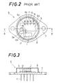
- Figs. 2 and 3 are respectively a plan sectional view showing the specific construction of the above described acceleration sensor and a cross sectional view taken along a line B - B shown in Fig. 2.
- a base plate 7 and a cap 8 secured to the upper surface of the base plate 7 constitute a package structure containing a housing space.
- a hybrid IC 9 is secured on the base plate 7 using adhesives (not shown).
- the hybrid IC 9 is used for constructing the impedance converting means 2, the filtering means 3 and the amplifying means 4 described above.
- a plurality of electrodes 9a to 9f for connection to outer portions are formed on the upper surface of the hybrid IC 9.
- Each of the electrodes 9a to 9d is electrically connected to a lead terminal 11 by a lead wire 10.
- a plurality of lead terminals 11 are passed through the base plate 7 and are extended downward.
- a supporting base 12 is secured on the base plate 7 using adhesives (not shown) beside the hybrid IC 9.
- a piezoelectric element 1 having electrodes (not shown) on both its major surfaces is secured on the supporting base 12 in a cantilevered shape.
- the electrode on the upper surface of the piezoelectric element 1 is electrically connected to the electrode 9f by a lead wire 10f, and the electrode on the lower surface of the piezoelectric element 1 is electrically connected to the supporting base 12.
- the supporting base 12 is electrically connected to the electrode 9e on the hybrid IC 9 by a lead wire 10e.
- the above described piezoelectric element 1 comprises one having a series type bimorph structure which is low in pyroelectric voltage.
- the above described package structure constituted by the base plate 7 and the cap 8 is hermetically sealed, and an inert gas, for example, nitrogen gas is sealed into the package structure so as to prevent oxidation.
- an inert gas for example, nitrogen gas is sealed into the package structure so as to prevent oxidation.
- the fault may not, in some cases, be quickly found out because the acceleration sensor does not have a fault self-diagnostic function.
- the conventional acceleration sensor 6 shown in Figs. 2 and 3 also have the following disadvantages. That is, when an excessive shock is externally given, there occurs a state where the supporting base 12 fixed to the base plate 7 using adhesives is stripped from the base plate 7 and the piezoelectric element 1, along with the supporting base 12, is not fixed to the other members, as represented by an imaginary line in Fig. 3. Accordingly, acceleration cannot, in some cases, be accurately detected by the piezoelectric element 1. Even if such a fault occurs, the electrical connection between the piezoelectric element 1 and the hybrid IC 9 is ensured through the lead wires 10e and 10f so long as the piezoelectric element 1 is fixed to the supporting base 12, so that the occurrence of the fault may not, in some cases, be detected.
- the present invention has been made so as to overcome the above described disadvantages of the conventional acceleration sensor and has for its object to provide an acceleration sensor capable of reliably detecting the occurrence of a fault.
- an acceleration sensor comprising a piezoelectric element outputting an electric signal corresponding to acceleration applied, signal processing means electrically connected to the above described piezoelectric element and for processing the electric signal outputted from the piezoelectric element, AC signal outputting means electrically connected to the above described piezoelectric element so as to generate an AC signal which is synchronized with the period of a timing signal externally inputted in response to the timing signal and apply the AC signal to the piezoelectric element, and a capacitor connected between the above described AC signal outputting means and the piezoelectric element.
- an acceleration sensor comprising an acceleration detecting portion comprising a piezoelectric element having electrodes on both its major surfaces and outputting an electric signal corresponding to acceleration applied and a supporting base for supporting the above described piezoelectric element, the acceleration detecting portion being further provided with a pair of detecting portions arranged so as to be brought into contact with the piezoelectric element and spaced apart from each other by a predetermined distance, signal processing means electrically connected to one of the electrodes of the piezoelectric element and for processing the signal outputted from the piezoelectric element, and signal outputting means electrically connected to one of the above described pair of detecting portions so as to cause a predetermined current to flow between the above described detecting portions and electrically connected to the above described signal processing means so as to output to the above described signal processing means a state signal representing the state of the acceleration detecting portion, the signal outputting means outputting the above described state signal in conformity with the variation of the current flowing between the detecting portions.
- a fault self-diagnostic function is provided in the acceleration sensor, as apparent from the embodiments described later. Even when there occurs a fault such as the cracking of the piezoelectric element or the stripping of the piezoelectric element from a portion to which the piezoelectric element is fixed, therefore, the fault which occurred can be quickly found out.
- an acceleration sensor comprising a piezoelectric element outputting an electric signal corresponding to acceleration applied, and signal processing means electrically connected to the above described piezoelectric element and for processing the output signal of the piezoelectric element, at least a part of the above described signal processing means being constituted by an electronic component having a flat upper surface, the above described piezoelectric element being fixed to the upper surface of the electronic component in a cantilevered shape.
- an electrode for making connection to the piezoelectric element is formed on the upper surface of the above described electronic component, and the piezoelectric element is electrically connected to the electrode and is fixed to the upper surface of the electronic component.
- the area of a portion to which the piezoelectric element is fixed on the upper surface of the electronic component is smaller than the area of a portion to which the electronic component itself is fixed. Accordingly, when a shock or the like is applied, not the electronic component but the piezoelectric element supported on the electronic component is stripped from the electronic component. As a result, the electrical connection between the piezoelectric element and the electronic component is interrupted, thereby to make it possible to quickly detect a fault caused by the stripping of the piezoelectric element.
- Fig. 4 is a schematic block diagram for explaining the construction of an acceleration sensor according to a first embodiment of the present invention
- Fig. 5 is a circuit diagram showing one example of an electric circuit of the acceleration sensor.
- a piezoelectric element 21 outputting an electric signal corresponding to acceleration G.
- a piezoelectric element having a series type bimorph structure having electrodes on both its major surfaces for example, is suitably used because it is low in pyroelectric voltage.
- the piezoelectric element 21 is deformed in conformity with the acceleration G applied to output an electric signal corresponding to the deformation.
- One of the electrodes of the piezoelectric element 21 is connected to a reference potential, as shown in Fig. 5.
- the other electrode of the piezoelectric element 21 is electrically connected to impedance converting means 22.
- the impedance converting means 22 is provided so as to convert the impedance of the electric signal applied from the piezoelectric element 21, and can be constituted by, for example, a field effect transistor TR1 and resistors R1 to R4 shown in Fig. 5.
- Filtering means 23 is provided in the succeeding stage of the impedance converting means 22.
- the filtering means 23 comprises a band-pass filter for attenuating or removing an unnecessary signal component, and can be constituted by, for example, an operational amplifier DA1, resistors R5 to R7 and capacitors C1 to C3 as shown in Fig. 5.
- Amplifying means 24 is provided in the succeeding stage of the filtering means 23 so as to amplify an output signal applied from the filtering means 23.
- the amplifying means 24 can be constituted by, for example, an operational amplifier DA2 and variable resistors VR1 and VR2 as shown in Fig. 5.
- the impedance converting means 22, the filtering means 23, and the amplifying means 24 constitute signal processing means according to the present invention.
- An output terminal B of the amplifying means 24 is an output terminal of the acceleration sensor according to the present embodiment.
- AC signal outputting means 26 is electrically connected to the electrode, to which the impedance converting means 22 is electrically connected, of the piezoelectric element 21 through a capacitor 25.
- the AC signal outputting means has an input terminal A, and a timing signal as described later is externally inputted to the input terminal A.
- the AC signal outputting means 26 is so constructed that an AC signal which is synchronized with the period of the timing signal inputted is outputted and the AC signal is applied to the piezoelectric element 21 through the capacitor 25.
- the AC signal outputting means 26 can be constituted by, for example, a transistor TR2, resistors R8 and R9, and variable resistors VR3 and VR4 as shown in Fig. 5.
- the fault diagnosis is made in cases, for example, a case where the acceleration sensor is used for an air bag device carried by an automobile and a case immediately before an automobile is driven. That is, when the engine of an automobile is started, for example, an instruction to start a fault diagnostic operation is issued to the acceleration sensor from outer control means 27 (see Fig. 4).
- a timing signal having a frequency f1 within a passband of the filtering means 23 is first outputted to the input terminal A of the AC signal outputting means 26 from the control means 27.
- the AC signal outputting means 26 outputs an AC signal which is synchronized with the period of the timing signal.
- the AC signal is applied to the piezoelectric element 21 through the capacitor 25.
- the piezoelectric element 21 has a certain capacitance value. Accordingly, the capacitance value of the piezoelectric element 21 is taken as Q1, the capacitance value of the capacitor 25 is taken as Q2, and a voltage of the AC signal outputted from the AC signal outputting means 26 is taken as V1.
- a voltage signal having the above described voltage V2 is impedance-converted in the impedance converting means 22, and an unnecessary signal component is attenuated or removed in the filtering means 23.
- the voltage signal is amplified by the amplifying means 24 and is outputted as a voltage signal V3 from the output terminal B.
- the AC signal outputting means 26 is so previously adjusted that the voltage signal V3 having a constant value is outputted from the output terminal B by inputting the timing signal having a frequency f1.
- This adjustment can be made by, for example, adjusting the variable resistors VR3 and VR4 in the circuit shown in Fig. 5.
- the voltage signal V3 outputted from the output terminal B of the acceleration sensor according to the present embodiment as described above is received in measuring and operating means 28 incorporated in the microcomputer.
- the respective variations of the voltage signal V3 corresponding to the timing signal having a frequency f1 and the voltage signal V4 corresponding to the timing signal having a frequency f2 are measured.
- the fault diagnosis of the acceleration sensor is made by comparing the measued values of V3 and V4 with normal values of V3 and V4 stored in the microcomputor.
- the piezoelectric element 21 and signal processing means comprising the impedance converting means 22, the filtering means 23 and the amplifying means 24 are connected in series, as apparent from Fig. 4. Even when an abnormality occurs in any structure, therefore, either one of the voltage signals V3 and V4 varies. Consequently, a fault can be quickly found out.
- the fault diagnostic function is added to the acceleration sensor by arranging the capacitor 25 between the AC signal outputting means 26 for outputting the AC signal which is synchronized with the period of the timing signal externally inputted and the piezoelectric element 21. Accordingly, a fault diagnostic device need not be provided outside the acceleration sensor, unlike the conventional acceleration sensor.
- Figs. 6 and 7 are respectively a block diagram for explaining the schematic construction of an acceleration sensor according to a second embodiment of the present invention and an electric circuit diagram showing one example of the specific circuit arrangement of the acceleration sensor.
- the acceleration detecting portion 32 comprises a piezoelectric element 31 having electrodes 31a and 31b on both its major surfaces, as shown in Fig. 7.
- a piezoelectric element having a series type bimorph structure which is low in pyroelectric voltage is preferably used, as in the first embodiment.
- the piezoelectric element 31 is fixed on a supporting base 33, as schematically shown in Fig. 7.
- a pair of detecting portions 34a and 34b is formed spaced apart from each other by a predetermined distance on the upper surface of the supporting base 33, and the pair of detecting portions 34a and 34b is electrically connected to the electrode 31a of the piezoelectric element 31.
- One of the detecting portions 34a is electrically connected to signal outputting means 35 as described hereafter.
- the other detecting portion 34b is electrically connected to a reference potential.
- the specific construction of the acceleration detecting portion 32 will be described hereafter with reference to, for example, Fig. 8.
- the other electrode 31b of the piezoelectric element 31 is electrically connected to signal processing means 36. That is, as shown in Fig. 6, the acceleration detecting portion 32 is electrically connected to the signal processing means 36 so that an output of the acceleration detecting portion 32 is applied to the signal processing means 36.
- the signal processing means 36 comprises impedance converting means 37, filtering means 38, and amplifying means 39.
- the impedance converting means 37 is provided so as to convert the impedance of a voltage signal applied from the acceleration detecting portion 32
- the filtering means 38 comprises a band-pass filter and is provided so as to attenuate or remove an out-of-band signal component
- the amplifying means 39 is provided so as to amplify a voltage signal applied from the filtering means 38.
- the signal processing means 36 is as shown in Fig. 7, it can be constructed in approximately the same manner as the impedance converting means 22, the filtering means 23 and the amplifying means 24 in the above described first embodiment. In Fig. 7, therefore, the same circuit elements as the circuit elements shown in Fig. 5 are assigned the same reference numerals and hence, the description thereof is not repeated.
- the signal outputting means 35 is connected to a power supply voltage Vcc, and is constituted by resistors R11 and R12 connected in series to each other. A node 40 between the resistors R11 and R12 is electrically connected to the signal processing means 36.
- a supporting base 33 is constituted by a pair of supporting members 33a and 33b arranged spaced apart from each other by a predetermined distance.
- Detecting portions 34a and 34b are formed on the respective supporting members 33a and 33b by applying electrode films. That is, the pair of detecting portions 34a and 34b is arranged spaced apart from each other by a predetermined distance.
- a piezoelectric element 31 is fixed on the detecting portions 34a and 34b with one of electrodes 31a on the bottom, and the electrode 31a is electrically connected to the detecting portions 34a and 34b.
- the signal outputting means 35 is electrically connected to the detecting portion 34a, as shown in Fig. 8, and the detecting portion 34b is connected to a reference potential.
- the signal outputting means 35 is connected in series to a predetermined potential source, and comprises a pair of resistors R11 and R12 for dividing the power supply voltage Vcc.
- respective one input terminals of the filtering means 38 and the amplifying means 39 are electrically connected to the node 40 between the resistors R11 and R12.
- one of the above described detecting portions 34a is electrically connected to the downstream side of the resistors R11 and R12. Consequently, a predetermined current I1 flows from the node 40 to the filtering means 38 and the amplifying means 39, and a predetermined current I2 flows from the downstream side of the resistors R11 and R12 to the detecting portion 34a.
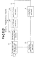
- the above described signal outputting means 35 may be constructed, as in a modified example shown in Fig. 11A. That is, the signal outputting means 35 may be so constructed that a circuit comprising resistors R13 to R15 and a transistor TR3 is provided in the succeeding stage of the node 40 between the resistors R11 and R12, and a current I3 corresponding to the predetermined current I1 from the node 40 is applied to respective one input terminals of the filtering means 38 and the amplifying means 39.
- the detecting portions 34a and 34b are electrically connected to each other by the electrode 31a on the lower surface of the piezoelectric element 31, as apparent from Fig. 8. Consequently, a predetermined current I2 applied from the above described signal outputting means 35 flows between the detecting portions 34a and 34b. That is, the current I2 flowing between the detecting portions 34a and 34b is always monitored by the signal processing means 36. If the current I2 varies, the current I1 flowing from the node 40 between the resistors R11 and R12 varies in conformity with the variation of the current I2.
- the current I2 flowing between the detecting portions 34a and 34b varies, so that the current I2 is reduced or does not flow.
- the current I1 flowing from the node 40 between the resistors R11 and R12 varies.
- a state signal representing the state of the acceleration detecting portion 32 that is, the cracking or the stripping of the piezoelectric element 31 constituting the acceleration detecting portion 32 is outputted from the signal outputting means 35 to the filtering means 38 and the amplifying means 39 constituting the signal processing means 36 in conformity with the variation in value of the above described current I2. Consequently, a signal outputted outward from the output terminal B of the acceleration sensor varies, thereby to make it possible to make the diagnosis of a fault in the acceleration sensor by the variation of the output signal in control means 41 connected to the output terminal B.
- the supporting base 33 constituting the acceleration detecting portion 32 comprises a pair of supporting members 33a and 33b, and the electrode films constituting the detecting portions 34a and 34b are applied to the upper surfaces of the supporting members 33a and 33b
- the detecting portions 34a and 34b may be provided separately from the electrode films formed on the supporting members 33a and 33b.
- the detecting portions 34a and 34b need not be respectively provided between the piezoelectric element 31 and the supporting members 33a and 33b.
- the detecting portions 34a and 34b may be arranged spaced apart from each other by a predetermined distance in another portion of the piezoelectric element 31.
- the construction of the acceleration detecting portion 32 is not limited to the construction shown in Fig. 8.
- the signal processing means 36 and the like in the acceleration sensor according to the present embodiment can be usually incorporated in a single electronic component, for example, a hybrid IC. Consequently, as shown in Fig. 9, the supporting base 33 may be replaced with a hybrid IC 42.
- a notch 42a is formed in the center of the hybrid IC 42
- a pair of supporting portions 42b and 42c is formed on both sides thereof
- detecting portions 34a and 34b are formed on the upper surface of the pair of the supporting portions 42b and 42c by applying electrode films.
- a piezoelectric element 31 is bonded and fixed on the detecting portions 34a and 34b with conductive adhesives. Consequently, an electrode 31a formed on one major surface of the piezoelectric element 31 is electrically connected to the electrode films constituting the detecting portions 34a and 34b.
- a piezoelectric element 31 may be fixed on a supporting base 33 in a cantilevered shape using conductive adhesives.
- a pair of electrode films is formed spaced apart from each other by a predetermined distance on the upper surface of the supporting base 33, thereby to constitute detecting portions 34a and 34b.
- an electrode 31a on the lower surface of the piezoelectric element 31 is formed in a substantially U shape by cutting away its central part as represented by a broken line in Fig. 10, and both ends of the electrode 31a in a substantially U shape are electrically connected to the detecting portions 34a and 34b, respectively.
- the filtering means 38 and the amplifying means 39 constituting the signal processing means 36 are electrically connected to the node 40 between the resistors R11 and R12 constituting the signal outputting means 35
- the present invention is not limited to the same. That is, as shown in Fig. 11B, a fault in the acceleration detecting portion 32 may be diagnosed by directly connecting the signal outputting means 35 and control means X to each other, applying a current from the above described node 40 to the control means X, and comparing the voltage signal applied from the output terminal B of the acceleration sensor and the state signal applied from the signal outputting means 35 with each other in the control means X.
- the acceleration sensor comprises the signal outputting means for outputting to the signal processing means the state signal representing the state of the acceleration detecting portion 32 comprising the piezoelectric element 31 and the supporting base 33, and the pair of detecting portions arranged spaced apart from each other by a predetermined distance in the acceleration detecting portion 32.
- the signal outputting means is so constructed as to output the above described state signal according to the variation of the current flowing between the detecting portions 34a and 34b.
- the current flowing between the above described detecting portions 34a and 34b varies, so that the state signal corresponding to the above described variation of the current is outputted from the signal outputting means, thereby to make it possible to quickly find out the fault which occurred.
- Figs. 12 and 13 are respectively a plan sectional view for explaining an acceleration sensor according to a third embodiment of the present invention and a schematic cross sectional view taken along a line A - A shown in Fig. 12.
- the third embodiment is characterized by a supporting structure of a piezoelectric element. Both the circuit arrangements in the above described first embodiment and second embodiment are applicable to the circuit arrangement in the third embodiment, and the acceleration sensor can be specifically constructed also in the first embodiment and the second embodiment using the construction of the third embodiment.
- an acceleration sensor 51 comprises a base plate 52 and a cap 53 secured to the upper surface of the base plate 52 at the peripheral edge, and the base plate 52 and the cap 53 constitute a package structure.
- a hybrid IC 54 is fixed on the base plate 52 using adhesives (not shown).
- the hybrid IC 54 has a structure containing signal processing means, AC signal outputting means 26 and/or signal outputting means 35, and the like in the first and second embodiments. That is, in the third embodiment, circuit portions such as the signal processing means, the signal outputting means 35 and/or the AC signal outputting means 26, and the like are constructed by using the hybrid IC 54 serving as a single electronic component.
- the upper surface of the hybrid IC 54 is made flat, and electrodes 54a to 54f for connection to outer portions are formed on the upper surface.
- Each of the electrodes 54a to 54d is electrically connected to a lead terminal 56 by a lead wire 55.
- the lead terminal 56 is passed through the base plate 52 and is extended downward from the base plate 52 in a state where it is electrically insulated from the base plate 52.
- the electrode 54e is electrically connected to an electrode 31b on the upper surface of a piezoelectric element 31 by a lead wire 57.
- the piezoelectric element 31 is directly secured to the upper surface of the hybrid IC 54 with conductive adhesives, and an electrode 31a on the lower surface of the piezoelectric element 31 is electrically connected to the electrode 54f with the above described conductive adhesives.
- the area of the bottom surface of the hybrid IC 54 is made larger than the area of the bottom surface of the supporting base 12 in the conventional acceleration sensor shown in Fig. 2. That is, the hybrid IC 54 used for this type of application usually has an area of base larger than that of the supporting base 12 shown in Fig. 2. Consequently, the hybrid IC 54 can be secured to the base plate 52 more firmly, as compared with the supporting base 12 shown in Fig. 2. Accordingly, in the acceleration sensor 51 according to the third embodiment, the hybrid IC 54 is more difficult to strip from the base plate 52, as compared with the supporting base 12 shown in Fig. 2, thereby to effectively prevent such a failure that the piezoelectric element and a member supporting the piezoelectric element are stripped from the base plate.
- the piezoelectric element 31 is secured to the upper surface of the hybrid IC 54 in a cantilevered shape. Consequently, when a large mechanical shock is applied, the hybrid IC 54 is not stripped from the base plate 52 but the piezoelectric element 31 is stripped from the upper surface of the hybrid IC 54 before the stripping. As a result, the electrical connection between the electrode 31a on the lower surface of the piezoelectric element 31 and the electrode 54f on the hybrid IC 54 shown in Fig. 12 is released, thereby to break an electric circuit. Consequently, when such a fault occurs, the occurrence of the fault is immediately detected by the operation of a fault self-diagnostic circuit incorporated in the hybrid IC 54.
- the piezoelectric element 31 is secured to the flat upper surface of the hybrid IC 54 in a cantilevered shape
- the piezoelectric element 31 may be secured to the upper surface of the hybrid IC in such a shape that its both ends are supported thereon, as in the modified example shown in Fig. 9 of the second embodiment.
- the acceleration sensor according to the fourth embodiment is characterized in that a temperature compensating capacitor is connected in parallel to a piezoelectric element.
- the constructions of the first to third embodiments are applicable to the other structures without any modification.
- the temperature compensating capacitor used in the fourth embodiment is used in the constructions of the first to third embodiments without any modification, thereby to make it possible to produce the function and effect described hereafter.
- an output voltage of the piezoelectric element is affected by the ambient temperature. Accordingly, temperature compensation has been conventionally made using a voltage amplifier. More specifically, in the conventional acceleration sensor, a piezoelectric element 61 is fixed on a supporting base 62 in a cantilevered shape within a case 60 represented by a broken line, as shown in Fig. 14. In addition, an impedance converter 63 is connected to the piezoelectric element 61, and a voltage amplifier 64 arranged outside the case 60 is connected to the impedance converter 63. In the voltage amplifier 64, the temperature compensation of the piezoelectric element 61 is made.
- the ambient temperature of the voltage amplifier 64 does not necessarily coincide with the ambient temperature of the piezoelectric element 61. Consequently, there arises the problem of making it impossible to make proper temperature compensation.
- the inventors of the present application have found that temperature compensation can be suitably made if a temperature compensating capacitor 72 is connected in parallel to a piezoelectric element 71 in close proximity to the piezoelectric element 71.
- reference numeral 73 denotes a supporting base.
- the supporting base 73 may be replaced with an electronic component such as the above described hybrid IC.
- reference numeral 74 denotes impedance converting means
- reference numeral 75 denotes a voltage amplifier.
- the voltage amplifier 75 can be constructed similarly to the amplifying means in the above described first and second embodiments. Consequently, the impedance converting means 74 and the voltage amplifier 75 can be constructed as a single electronic component, for example, a hybrid IC within a case 70.
- the rate of variation of output voltage in a case where the output voltage V is changed by ⁇ V due to the rise in unit temperature is ⁇ V / V.
- the output voltage V of the piezoelectric element is proportional to a stress ( ⁇ G) produced by acceleration G at that time and the piezoelectric stress constant d31 of the piezoelectric element, and is inversely proportional to the capacitance Qs of the piezoelectric element.
- the inventors of the present application has found that if the above described temperature compensating capacitor 72 is connected in parallel to the piezoelectric element 71 in close proximity to the piezoelectric element 71, temperature compensation can be reliably made by selecting the capacitance of the capacitor 72.
- the capacitance Qt at the reference temperature of the capacitor 72 and the rate of variation of capacitance with temperature thereof ( ⁇ Qt / Qt) are suitably selected, the rate of variation of piezoelectric stress constant of a parallel circuit and the rate of variation of capacitance thereof are approximately equal to each other, thereby to obtain an output voltage which is not affected by the ambient temperature.
- the type of capacitor 72 used is suitably selected to find the value of the rate of variation of capacitance of the capacitor 72, and this value and the other known values are substituted in the above described equation (8) to find the required capacitance Qt of the capacitor 72.
- the rate of variation of piezoelectric stress constant and the rate of variation of capacitance of the parallel circuit of the piezoelectric element and the capacitor can be made approximately equal to each other by only selecting the capacitance of the capacitor 72 connected in parallel to the piezoelectric element 71 in the above described manner. Consequently, even if the ambient temperature changes, the amount of change in output due to the change in piezoelectric stress constant is canceled by the amount of change in capacitance. As a result, an output voltage which is not affected by the ambient temperature is obtained. Since the above described capacitor 72 is provided in close proximity to the piezoelectric element 71, and the capacitor 72 is always operated at approximately the same temperature as the piezoelectric element 71, therefore, it is possible to accurately make temperature compensation.
- the fifth embodiment is characterized in that in an acceleration sensor so constructed that an electronic component containing a signal processing circuit and the like is arranged on a base plate, a cushioning member for absorbing a thermal shock produced between the base plate and the above described electronic component due to the difference in coefficient of thermal expansion or modulus of elasticity is provided between the base plate and the electronic component.
- the cushioning member is also applicable to each of the acceleration sensors in the above described first to fourth embodiments.
- the thermal shock produced due to the difference in coefficient of thermal expansion or modulus of elasticity is absorbed by the above described cushioning member, so that an excessive thermal stress is not exerted on the electronic component for constructing signal processing means and the like. Consequently, the possibility of causing damages to the electronic component due to the thermal shock is prevented, thereby to enhance the reliability of the acceleration sensor.
- the thermal shock is absorbed by the above described cushioning member. Accordingly, even if a wiring pattern or a resistor film is formed on the bottom surface of the above described electronic component, it is hardly damaged. Accordingly, it is possible to also form a wiring pattern or a resistor film superior in reliability on the bottom surface of the electronic component, thereby to make it possible to make the electronic component used smaller in size and higher in integration density.
- the acceleration sensor comprises a piezoelectric element 81 outputting an electric signal corresponding to acceleration and a hybrid IC 82 serving as an electronic component containing various types of signal processing circuits for processing a signal outputted from the piezoelectric element 81.
- the piezoelectric element 81 has a strip shape
- the hybrid IC 82 has a rectangular plate shape.
- the piezoelectric element 81 is held in the center of the hybrid IC 82 in a cantilevered shape. That is, a through hole 83 for mounting the piezoelectric element is formed in the center of the hybrid IC 82. A fixed end 81a of the piezoelectric element 81 is secured to an edge of the above described through hole 83, and a free end 81b thereof is so arranged as to face the through hole 83.
- a tip-type electronic component 84 and a wiring pattern are secured or formed on the upper surface of the hybrid IC 82.
- a component such as a resistor film or a wiring pattern, an electrode and the like are also formed on the bottom surface of the hybrid IC 82, which are not shown.
- the hybrid IC 82 and the piezoelectric element 81 are connected to each other through a bonding wire 86.
- the upper surface of the hybrid IC 82 is covered with a cover body 87 made of a metal, a conductive resin or a material obtained by metal-plating a synthetic resin.
- a plurality of connecting terminals for connection to outer portions 88 are attached to one end of the hybrid IC 82, and are projected sideward from the hybrid IC 82.
- the acceleration sensor according to the present embodiment comprises a base plate 89 made of a metal on which the above described hybrid IC 82 is mounted and an insulating resin film 90.
- This insulating resin film 90 serves as a cushioning member in the present invention.
- the base plate 89 comprises a mounting stage 89a for mounting the hybrid IC 82 in its central part, and the insulating resin film 90 is affixed on the mounting stage 89a with, for example, epoxy adhesives.
- a polymer film such as a polyimide film having a coefficient of thermal expansion of 8 ⁇ 10 ⁇ 6 to 17 ⁇ 10 ⁇ 6/°C and having modulus of elasticity of 380 kg/mm2 and a polyethylene terephthalate film having a coefficient of thermal expansion of 30 ⁇ 10 ⁇ 6 to 50 ⁇ 10 ⁇ 6/°C and having modulus of elasticity of 400 kg/mm2 are suitable as the insulating resin film 90, and approximately 10 ⁇ m is sufficient and particularly, approximately 30 ⁇ m is suitable for the thickness thereof.
- the hybrid IC 82 is affixed on the insulating resin film 90 affixed to the mounting stage 89a through, for example, epoxy adhesives.
- epoxy adhesives In order to firmly bond the base plate 89, the insulating resin film 90, and the hybrid IC 82, it is preferable that both surfaces of the insulating resin film 90 are previously subjected to sandblasting.
- the area above the hybrid IC 82 positioned and fixed on the base plate 89 is covered with a cap 91.
- the cap 91 is made of a metal or a conductive resin, and has dimensions covering the mounting stage 89a of the base plate 89.
- parts on the side of the bottom surface and one side surface of the cap 91 are opened.
- the lower parts of the side surfaces of the cap 91 are secured to the periphery of the mounting stage 89a so that the cap 91 is fixed on the base plate 89. Consequently, the hybrid IC 82 is covered with the cap 91 in a state where the connecting terminals for connection to outer portions 88 are projected sideward from the opened part of the cap 91.
- the cap 91 is filled with an insulating resin 92 such as silicone resin for the purpose of hermetical sealing. Since the piezoelectric element 81 is surrounded by the cover body 87, however, a space for vibration A of the piezoelectric element 81 is ensured.
- the hybrid IC 82 contains various circuits as described in the first and second embodiments, for example, signal processing circuits such as an impedance converting circuit, a filter circuit, an amplifying circuit and the like.
- the hybrid IC 82 and the base plate 89 differ from each other in coefficient of thermal expansion and modulus of elasticity (the coefficient of thermal expansion of the hybrid IC 82 is 2 ⁇ 10 ⁇ 6 to 7 ⁇ 10 ⁇ 6/°C and the modulus of elasticity thereof is 1 ⁇ 104 to 3 ⁇ 104 kg/mm2), while the coefficient of thermal expansion of the base plate made of metal is 10 ⁇ 10 ⁇ 6 to 30 ⁇ 10 ⁇ 6/°C and the modulus of elasticity thereof is 0.1 ⁇ 104 to 2 ⁇ 104 kg/mm2), as in the conventional acceleration sensor. Consequently, when the temperature violently changes, a thermal shock can be produced between the hybrid IC 82 and the base plate 89. However, the above described insulating resin film 90 is interposed therebetween, which functions as a cushioning member to absorb the above described thermal shock Consequently, there occur no damages such as cracking or chipping and stripping in the hybrid IC 82.
- the piezoelectric element 81 is mounted on the hybrid IC 82.
- the hybrid IC 82 is reliably fixed on the base plate 89 without being stripped by the function of the insulating resin film 90. Consequently, a failure making it impossible to measure acceleration, that is, the stripping of the piezoelectric element 81 does not easily occur.
- the thermal shock is absorbed by the insulating resin film 90, so that there is no possibility of damaging the wiring pattern or the resistor film formed on the bottom surface of the hybrid IC 82.
- the surface of the wiring pattern or the resistor film is physically protected by the insulating resin film 90.
- the electrical insulation between the bottom surface of the hybrid IC 82 and the base plate 89 is ensured. Accordingly, it is possible to form a wiring pattern or a resistor film superior in reliability on the bottom surface of the hybrid IC 82, thereby to make it possible to make the hybrid IC 82 smaller in size and higher in integration density.
- the present invention is not limited to the same.
- insulating adhesives used for bonding can be also used as the above described cushioning member.
- the insulating adhesives must be so applied as to have a thickness of at least approximately 10 ⁇ m in order to obtain the cushioning effect.
- the connecting terminals for connection to outer portions 88 are directly mounted on the hybrid IC 82, and are not mounted on the base plate 89. Consequently, it is possible to omit complicated work such as work of mounting the connecting terminals for connection to outer portions 88 so as to pass through the base plate 89 or work of insulating the connecting terminals for connection to outer portions 88 and the base plate 89 from each other.
- the above described bonding wire 86 need not be necessarily used so as to connect the piezoelectric element 81 and the hybrid IC 82 to each other.
- the piezoelectric element 81 and the hybrid IC 82 may be connected to each other using solder, conductive adhesives or the like.
- the piezoelectric element 81 a piezoelectric element of a bimorph type, a piezoelectric element of a unimorph type, and a piezoelectric element of a shear mode type (shearing type) may be used.
- the piezoelectric element 81 of a shear mode type the piezoelectric element 81 and the hybrid IC 82 can be connected to each other without using the bonding wire 86 from a structural point of view.
- the piezoelectric element 81 is fixed to the upper surface of the hybrid IC 82 in a cantilevered shape
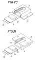
- the fifth embodiment is not limited to the same. That is, as shown in an exploded perspective view of Fig. 19, a piezoelectric element 81 may be fixed to a flat upper surface of a hybrid IC 82 so as to support both ends of the piezoelectric element 81 on both sides by edges opposed to each other of a through hole 83 in the hybrid IC 82.
- a base plate 89 and a cap 91 may be integrated, and grooves for positioning 92 may be respectively formed on the inside of a pair of side surfaces opposed to each other so as to extend in the horizontal direction. If the width of the grooves 92 is made approximately equal to the thickness of the hybrid IC 82, it is possible to simply mount the hybrid IC 82. Moreover, it is possible to reliably mount the hybrid IC 82. In addition, the necessity of bonding the base plate 89 and the cap 91 to each other is eliminated, thereby to increase the strength of the entire package structure.
- a member for preventing silicone resin or the like with which the cap 91 is filled from flowing in is mounted on the reverse surface of a mounting hole of a piezoelectric element (that is, a mounting hole corresponding to the through hole 83 shown in Fig. 17), which is not shown in Fig. 20.
- the hybrid IC 82 can be mounted with it being turned over by changing the position of the grooves for positioning 92, which is not shown.
- the above described grooves for positioning 92 may be replaced with inward projections for positioning 93 extending in the horizontal direction, and the lower surface of the projection 93 may be utilized as a surface for positioning in inserting the hybrid IC 82.
- an insulating plate 94 having a predetermined thickness may be affixed to the reverse surface of the hybrid IC 82 so as to obtain positioning on the lower side of the hybrid IC 82. That is, the thickness of the above described insulating plate 94 may be so selected that the thickness of the insulating plate 94 and the thickness of the hybrid IC 82c are approximately equal to the distance between the lower surface of the projection 93 and the bottom surface of the cap 91.
- the piezoelectric element a suitable piezoelectric element such as not only a piezoelectric element of a bimorph type but also a piezoelectric element of a unimorph type, a piezoelectric element of a shear mode type or the like.
Landscapes
- Physics & Mathematics (AREA)
- General Physics & Mathematics (AREA)
- Pressure Sensors (AREA)
- Air Bags (AREA)
- Measurement Of Mechanical Vibrations Or Ultrasonic Waves (AREA)
- Force Measurement Appropriate To Specific Purposes (AREA)
- Measuring Fluid Pressure (AREA)
Priority Applications (2)
| Application Number | Priority Date | Filing Date | Title |
|---|---|---|---|
| EP94120004A EP0646798B1 (fr) | 1991-09-24 | 1992-09-22 | Capteur d'accélération |
| EP94120005A EP0646799B1 (fr) | 1991-09-24 | 1992-09-22 | Capteur d'accélération |
Applications Claiming Priority (10)
| Application Number | Priority Date | Filing Date | Title |
|---|---|---|---|
| JP243299/91 | 1991-09-24 | ||
| JP24329991A JP2900658B2 (ja) | 1991-09-24 | 1991-09-24 | 加速度センサ |
| JP255284/91 | 1991-10-02 | ||
| JP3255284A JPH0792473B2 (ja) | 1991-10-02 | 1991-10-02 | 圧電式加速度センサ |
| JP316203/91 | 1991-11-29 | ||
| JP3316203A JP2745908B2 (ja) | 1991-11-29 | 1991-11-29 | 加速度センサ |
| JP3346735A JP2745919B2 (ja) | 1991-12-27 | 1991-12-27 | 加速度センサ |
| JP346735/91 | 1991-12-27 | ||
| JP1762792A JP2705426B2 (ja) | 1992-02-03 | 1992-02-03 | 加速度センサ |
| JP17627/92 | 1992-02-03 |
Related Child Applications (2)
| Application Number | Title | Priority Date | Filing Date |
|---|---|---|---|
| EP94120004.0 Division-Into | 1992-09-22 | ||
| EP94120005.7 Division-Into | 1992-09-22 |
Publications (2)
| Publication Number | Publication Date |
|---|---|
| EP0534366A1 true EP0534366A1 (fr) | 1993-03-31 |
| EP0534366B1 EP0534366B1 (fr) | 1996-06-05 |
Family
ID=27519939
Family Applications (3)
| Application Number | Title | Priority Date | Filing Date |
|---|---|---|---|
| EP94120005A Expired - Lifetime EP0646799B1 (fr) | 1991-09-24 | 1992-09-22 | Capteur d'accélération |
| EP94120004A Expired - Lifetime EP0646798B1 (fr) | 1991-09-24 | 1992-09-22 | Capteur d'accélération |
| EP92116187A Expired - Lifetime EP0534366B1 (fr) | 1991-09-24 | 1992-09-22 | Capteur d'accélération |
Family Applications Before (2)
| Application Number | Title | Priority Date | Filing Date |
|---|---|---|---|
| EP94120005A Expired - Lifetime EP0646799B1 (fr) | 1991-09-24 | 1992-09-22 | Capteur d'accélération |
| EP94120004A Expired - Lifetime EP0646798B1 (fr) | 1991-09-24 | 1992-09-22 | Capteur d'accélération |
Country Status (3)
| Country | Link |
|---|---|
| US (2) | US5438859A (fr) |
| EP (3) | EP0646799B1 (fr) |
| DE (3) | DE69211269T2 (fr) |
Cited By (6)
| Publication number | Priority date | Publication date | Assignee | Title |
|---|---|---|---|---|
| EP0638782A1 (fr) * | 1993-08-02 | 1995-02-15 | New Sd, Inc. | Capteur de vitesse de rotation avec circuit de test intégré |
| EP0689055A1 (fr) * | 1994-06-23 | 1995-12-27 | Murata Manufacturing Co., Ltd. | Accéléromètre |
| FR2731278A1 (fr) * | 1994-08-29 | 1996-09-06 | Seiko Instr Inc | Detecteur d'acceleration a semi-conducteur |
| EP1156337A4 (fr) * | 1999-01-26 | 2003-07-02 | Airbag Systems Co Ltd | Capteur d'acceleration et systeme de detection d'acceleration |
| CN106153981A (zh) * | 2016-05-24 | 2016-11-23 | 中国人民解放军海军工程大学 | Iepe型智能加速度传感器及其工作方法 |
| GB2625258A (en) * | 2022-12-06 | 2024-06-19 | Secr Defence | Improvements in accelerometers |
Families Citing this family (28)
| Publication number | Priority date | Publication date | Assignee | Title |
|---|---|---|---|---|
| EP0715722B1 (fr) * | 1993-08-24 | 1998-06-03 | A/S BRÜEL & KJAER | Appareil de detection d'une defaillance dans un accelerometre |
| US6911727B1 (en) | 1995-06-06 | 2005-06-28 | Analog Devices, Inc. | Package for sealing an integrated circuit die |
| US6323550B1 (en) * | 1995-06-06 | 2001-11-27 | Analog Devices, Inc. | Package for sealing an integrated circuit die |
| EP0852337A1 (fr) * | 1996-12-24 | 1998-07-08 | STMicroelectronics S.r.l. | Capteur inertiel semi-conducteur, hermétiquement étanche |
| JP3233059B2 (ja) * | 1997-03-07 | 2001-11-26 | 株式会社村田製作所 | 超音波センサ |
| EP0886144B1 (fr) * | 1997-06-19 | 2006-09-06 | STMicroelectronics S.r.l. | Capteur scellé hermétiquement avec microstructure mobile |
| JP2000346865A (ja) * | 1999-03-26 | 2000-12-15 | Ngk Insulators Ltd | 加速度センサ素子の感度調整方法 |
| JP2001349900A (ja) * | 1999-12-28 | 2001-12-21 | Fujitsu Ltd | 加速度センサ及び加速度センサ装置 |
| DE10031793C1 (de) * | 2000-07-04 | 2002-02-07 | Peter Apel | Piezoelektrischer Sensor |
| DE10113802B4 (de) * | 2001-03-21 | 2007-10-18 | Siemens Ag | Vorrichtung zum Ansteuern eines piezoelektrischen Stellgliedes |
| US6531884B1 (en) * | 2001-08-27 | 2003-03-11 | Rosemount Inc. | Diagnostics for piezoelectric sensor |
| DE10223553B4 (de) * | 2002-05-27 | 2004-08-05 | Siemens Ag | Verfahren zur Ansteuerung eines Aktors und zugehörige Steuereinrichtung |
| RU2212672C1 (ru) * | 2002-12-25 | 2003-09-20 | Открытое акционерное общество "ЭЛПА" | Пьезоэлектрический датчик ускорения |
| US7646095B2 (en) * | 2003-09-30 | 2010-01-12 | Panasonic Corporation | Semiconductor device |
| US20050225201A1 (en) * | 2004-04-02 | 2005-10-13 | Par Technologies, Llc | Piezoelectric devices and methods and circuits for driving same |
| US7287965B2 (en) * | 2004-04-02 | 2007-10-30 | Adaptiv Energy Llc | Piezoelectric devices and methods and circuits for driving same |
| US7290993B2 (en) * | 2004-04-02 | 2007-11-06 | Adaptivenergy Llc | Piezoelectric devices and methods and circuits for driving same |
| US7312554B2 (en) * | 2004-04-02 | 2007-12-25 | Adaptivenergy, Llc | Piezoelectric devices and methods and circuits for driving same |
| DE102004050674B4 (de) * | 2004-10-18 | 2018-02-08 | Volkswagen Ag | Befestigungsanordnung für elektrische Komponenten in einem Fahrzeug |
| JP4779423B2 (ja) * | 2005-04-26 | 2011-09-28 | パナソニック株式会社 | 振動型圧電加速度センサ素子とこれを用いた振動型圧電加速度センサ |
| JP2007155700A (ja) * | 2005-11-09 | 2007-06-21 | Denso Corp | 車両用衝突検知装置 |
| JP5083287B2 (ja) * | 2009-09-11 | 2012-11-28 | セイコーエプソン株式会社 | 検出装置、物理量測定装置及び電子機器 |
| JP4821900B2 (ja) * | 2009-09-11 | 2011-11-24 | セイコーエプソン株式会社 | 検出装置、物理量測定装置及び電子機器 |
| JP6186598B2 (ja) * | 2012-04-20 | 2017-08-30 | パナソニックIpマネジメント株式会社 | 慣性力センサ |
| ITTO20120542A1 (it) | 2012-06-20 | 2013-12-21 | St Microelectronics Srl | Dispositivo microelettromeccanico con instradamento dei segnali attraverso un cappuccio protettivo e metodo per controllare un dispositivo microelettromeccanico |
| DE102014213217A1 (de) * | 2014-07-08 | 2016-01-14 | Continental Teves Ag & Co. Ohg | Körperschallentkopplung an mit Geberfeldern arbeitenden Sensoren |
| JP6508326B2 (ja) * | 2015-03-12 | 2019-05-08 | 株式会社村田製作所 | 加速度検出装置及びその製造方法 |
| US10054607B2 (en) * | 2016-05-12 | 2018-08-21 | Google Llc | Using accelerometer to self-test piezoelectric component in a portable device |
Citations (3)
| Publication number | Priority date | Publication date | Assignee | Title |
|---|---|---|---|---|
| FR2550145A1 (fr) * | 1983-08-04 | 1985-02-08 | Bosch Gmbh Robert | Dispositif de declenchement pour systeme de retenue dans des vehicules automobiles |
| EP0374870A2 (fr) * | 1988-12-23 | 1990-06-27 | Mitsubishi Denki Kabushiki Kaisha | Capteur d'accélération |
| GB2239096A (en) * | 1989-12-11 | 1991-06-19 | Kellett Michael A | Signal processing circuits |
Family Cites Families (31)
| Publication number | Priority date | Publication date | Assignee | Title |
|---|---|---|---|---|
| BE476550A (fr) * | 1945-02-08 | |||
| US3233466A (en) * | 1963-06-24 | 1966-02-08 | Bendix Corp | Piezoelectric accelerometer |
| US3479536A (en) * | 1967-03-14 | 1969-11-18 | Singer General Precision | Piezoelectric force transducer |
| US3733590A (en) * | 1971-04-15 | 1973-05-15 | A Kaufman | Optimum electrode configuration ceramic memories with ceramic motor element and mechanical damping |
| US4155257A (en) * | 1977-05-23 | 1979-05-22 | The Singer Company | Temperature compensated vibrating beam accelerometer |
| US4197478A (en) * | 1979-01-25 | 1980-04-08 | Southwest Research Institute | Electronically tunable resonant accelerometer |
| JPS5822912A (ja) * | 1981-08-03 | 1983-02-10 | Nippon Denso Co Ltd | 入力信号の変化率検出装置 |
| US4450914A (en) * | 1982-01-25 | 1984-05-29 | Dresser Industries, Inc. | Well treatment valve |
| JPS58137329A (ja) * | 1982-02-10 | 1983-08-15 | Nec Corp | 入力信号線断線検出回路 |
| US4459505A (en) * | 1982-05-28 | 1984-07-10 | Rca Corporation | Piezoelectric ultor voltage generator for a television receiver |
| JPS59181585A (ja) * | 1983-03-31 | 1984-10-16 | Toshiba Corp | 変位発生装置 |
| JPS59204477A (ja) * | 1983-05-04 | 1984-11-19 | Nippon Kogaku Kk <Nikon> | 超音波モーターの駆動制御回路 |
| FR2546303B1 (fr) * | 1983-05-20 | 1985-07-05 | Thomson Csf | Capteur de forces a ondes elastiques de surface |
| FR2558263B1 (fr) * | 1984-01-12 | 1986-04-25 | Commissariat Energie Atomique | Accelerometre directif et son procede de fabrication par microlithographie |
| JPS6196340A (ja) * | 1984-10-18 | 1986-05-15 | Mitsubishi Electric Corp | 空気調和機 |
| JPH0660906B2 (ja) * | 1984-12-18 | 1994-08-10 | 日産自動車株式会社 | 半導体加速度センサ |
| GB2174500B (en) * | 1985-05-04 | 1988-02-10 | Stc Plc | Accelerometer |
| US4676104A (en) * | 1985-08-06 | 1987-06-30 | United Technologies Corporation | Surface skimming bulk acoustic wave accelerometer |
| JPS6320663A (ja) * | 1986-07-15 | 1988-01-28 | Brother Ind Ltd | ワ−ドプロセツサ |
| JPH07122643B2 (ja) * | 1986-11-27 | 1995-12-25 | 日本電装株式会社 | 加速度検出装置 |
| JPS63206663A (ja) * | 1987-02-23 | 1988-08-25 | Mitsubishi Electric Corp | 歪ゲ−ジ式加速度センサ |
| US4950914A (en) * | 1987-03-30 | 1990-08-21 | Honda Giken Kogyo Kabushiki Kaisha | Collision detection system for a vehicle |
| EP0340476B1 (fr) * | 1988-04-11 | 1993-06-16 | Nippondenso Co., Ltd. | Capteur d'accélération |
| JPH027879A (ja) * | 1988-06-27 | 1990-01-11 | Matsushita Electric Ind Co Ltd | 超音波モータ駆動装置 |
| JPH0215707A (ja) * | 1988-07-01 | 1990-01-19 | Seiko Electronic Components Ltd | 水晶振動子の支持構造 |
| JPH0248865A (ja) * | 1988-08-10 | 1990-02-19 | Hitachi Ltd | 水平・垂直輪郭強調回路 |
| IT1223933B (it) * | 1988-11-23 | 1990-09-29 | Marelli Autronica | Trasduttore di accelerazione ad effetto capacitivo |
| JPH032569A (ja) * | 1989-05-30 | 1991-01-08 | Ricoh Co Ltd | 加速度センサ |
| US5130600A (en) * | 1989-06-02 | 1992-07-14 | Mitsubishi Petrochemical Co., Ltd. | Acceleration sensor |
| DE3942011C3 (de) * | 1989-12-20 | 1996-10-17 | Telefunken Microelectron | Einrichtung zur Auslösung einer passiven Sicherheitseinrichtung für Fahrzeuginsassen |
| US5239871A (en) * | 1990-12-17 | 1993-08-31 | Texas Instruments Incorporated | Capacitive accelerometer |
-
1992
- 1992-09-22 DE DE69211269T patent/DE69211269T2/de not_active Expired - Lifetime
- 1992-09-22 DE DE69232273T patent/DE69232273T2/de not_active Expired - Lifetime
- 1992-09-22 EP EP94120005A patent/EP0646799B1/fr not_active Expired - Lifetime
- 1992-09-22 EP EP94120004A patent/EP0646798B1/fr not_active Expired - Lifetime
- 1992-09-22 DE DE69232272T patent/DE69232272T2/de not_active Expired - Lifetime
- 1992-09-22 EP EP92116187A patent/EP0534366B1/fr not_active Expired - Lifetime
- 1992-09-24 US US07/950,478 patent/US5438859A/en not_active Expired - Lifetime
-
1995
- 1995-02-22 US US08/392,084 patent/US5517845A/en not_active Expired - Lifetime
Patent Citations (3)
| Publication number | Priority date | Publication date | Assignee | Title |
|---|---|---|---|---|
| FR2550145A1 (fr) * | 1983-08-04 | 1985-02-08 | Bosch Gmbh Robert | Dispositif de declenchement pour systeme de retenue dans des vehicules automobiles |
| EP0374870A2 (fr) * | 1988-12-23 | 1990-06-27 | Mitsubishi Denki Kabushiki Kaisha | Capteur d'accélération |
| GB2239096A (en) * | 1989-12-11 | 1991-06-19 | Kellett Michael A | Signal processing circuits |
Cited By (10)
| Publication number | Priority date | Publication date | Assignee | Title |
|---|---|---|---|---|
| EP0638782A1 (fr) * | 1993-08-02 | 1995-02-15 | New Sd, Inc. | Capteur de vitesse de rotation avec circuit de test intégré |
| EP0689055A1 (fr) * | 1994-06-23 | 1995-12-27 | Murata Manufacturing Co., Ltd. | Accéléromètre |
| US5734087A (en) * | 1994-06-23 | 1998-03-31 | Murata Manufacturing Co., Ltd. | Acceleration sensor |
| CN1041236C (zh) * | 1994-06-23 | 1998-12-16 | 株式会社村田制作所 | 加速度传感器 |
| FR2731278A1 (fr) * | 1994-08-29 | 1996-09-06 | Seiko Instr Inc | Detecteur d'acceleration a semi-conducteur |
| US6005275A (en) * | 1994-08-29 | 1999-12-21 | Seiko Instruments Inc. | Semiconductor acceleration sensor with cantilever |
| EP1156337A4 (fr) * | 1999-01-26 | 2003-07-02 | Airbag Systems Co Ltd | Capteur d'acceleration et systeme de detection d'acceleration |
| CN106153981A (zh) * | 2016-05-24 | 2016-11-23 | 中国人民解放军海军工程大学 | Iepe型智能加速度传感器及其工作方法 |
| CN106153981B (zh) * | 2016-05-24 | 2022-09-27 | 中国人民解放军海军工程大学 | Iepe型智能加速度传感器及其工作方法 |
| GB2625258A (en) * | 2022-12-06 | 2024-06-19 | Secr Defence | Improvements in accelerometers |
Also Published As
| Publication number | Publication date |
|---|---|
| EP0646799B1 (fr) | 2001-12-05 |
| DE69211269D1 (de) | 1996-07-11 |
| DE69211269T2 (de) | 1997-01-23 |
| EP0646799A3 (fr) | 1998-12-16 |
| EP0646798A3 (fr) | 1998-12-16 |
| DE69232273D1 (de) | 2002-01-17 |
| DE69232272T2 (de) | 2002-08-08 |
| US5517845A (en) | 1996-05-21 |
| DE69232273T2 (de) | 2002-08-08 |
| EP0534366B1 (fr) | 1996-06-05 |
| US5438859A (en) | 1995-08-08 |
| DE69232272D1 (de) | 2002-01-17 |
| EP0646798B1 (fr) | 2001-12-05 |
| EP0646798A2 (fr) | 1995-04-05 |
| EP0646799A2 (fr) | 1995-04-05 |
Similar Documents
| Publication | Publication Date | Title |
|---|---|---|
| EP0534366A1 (fr) | Capteur d'accélération | |
| US6561030B2 (en) | Acceleration sensor | |
| US5864062A (en) | Semiconductor acceleration sensor | |
| JP3020426B2 (ja) | トランスデューサアセンブリ、回路基板に取り付けるためのトランスデューサデバイス、及び回路基板にトランスデューサを取り付ける方法 | |
| US5164328A (en) | Method of bump bonding and sealing an accelerometer chip onto an integrated circuit chip | |
| US12163976B2 (en) | Acceleration transducer | |
| US12105112B2 (en) | Acceleration transducer | |
| US5460044A (en) | Semiconductor acceleration detecting apparatus | |
| JPWO1999060413A1 (ja) | 加速度センサ及びこの加速度センサを用いた加速度装置 | |
| US11747361B2 (en) | Acceleration transducer | |
| JP3281217B2 (ja) | 半導体式加速度センサと該センサのセンサ素子の特性評価方法 | |
| US5379640A (en) | Semiconductor acceleration detecting apparatus | |
| US5481915A (en) | Acceleration sensor with direct mounting | |
| JP2005114440A (ja) | 故障診断可能な静電容量検出型加速度センサ | |
| US5614673A (en) | Acceleration sensing device | |
| JP2524518B2 (ja) | 加速度センサ | |
| JPH0580075A (ja) | 加速度センサ | |
| JPH0447271A (ja) | 加速度センサ及びその出力電圧調整方法 | |
| JP2745908B2 (ja) | 加速度センサ | |
| JPH0961448A (ja) | 加速度センサの部品配置構造 | |
| JPH0640866U (ja) | 加速度センサ | |
| KR200183336Y1 (ko) | 표면 탄성파 필터의 표면실장형 패키지 | |
| JPH06109760A (ja) | 加速度センサ | |
| JPH1144704A (ja) | 加速度センサ |
Legal Events
| Date | Code | Title | Description |
|---|---|---|---|
| PUAI | Public reference made under article 153(3) epc to a published international application that has entered the european phase |
Free format text: ORIGINAL CODE: 0009012 |
|
| AK | Designated contracting states |
Kind code of ref document: A1 Designated state(s): DE FR GB IT SE |
|
| 17P | Request for examination filed |
Effective date: 19930429 |
|
| 17Q | First examination report despatched |
Effective date: 19940623 |
|
| GRAH | Despatch of communication of intention to grant a patent |
Free format text: ORIGINAL CODE: EPIDOS IGRA |
|
| GRAA | (expected) grant |
Free format text: ORIGINAL CODE: 0009210 |
|
| AK | Designated contracting states |
Kind code of ref document: B1 Designated state(s): DE FR GB IT SE |
|
| XX | Miscellaneous (additional remarks) |
Free format text: TEILANMELDUNG 94120004.0 EINGEREICHT AM 22/09/92. |
|
| REF | Corresponds to: |
Ref document number: 69211269 Country of ref document: DE Date of ref document: 19960711 |
|
| ET | Fr: translation filed | ||
| ITF | It: translation for a ep patent filed | ||
| PLBE | No opposition filed within time limit |
Free format text: ORIGINAL CODE: 0009261 |
|
| 26N | No opposition filed | ||
| REG | Reference to a national code |
Ref country code: GB Ref legal event code: IF02 |
|
| PGFP | Annual fee paid to national office [announced via postgrant information from national office to epo] |
Ref country code: DE Payment date: 20100915 Year of fee payment: 19 |
|
| PGFP | Annual fee paid to national office [announced via postgrant information from national office to epo] |
Ref country code: FR Payment date: 20110922 Year of fee payment: 20 Ref country code: GB Payment date: 20110921 Year of fee payment: 20 Ref country code: SE Payment date: 20110913 Year of fee payment: 20 |
|
| PGFP | Annual fee paid to national office [announced via postgrant information from national office to epo] |
Ref country code: IT Payment date: 20110921 Year of fee payment: 20 |
|
| REG | Reference to a national code |
Ref country code: DE Ref legal event code: R071 Ref document number: 69211269 Country of ref document: DE |
|
| REG | Reference to a national code |
Ref country code: DE Ref legal event code: R071 Ref document number: 69211269 Country of ref document: DE |
|
| REG | Reference to a national code |
Ref country code: GB Ref legal event code: PE20 Expiry date: 20120921 |
|
| REG | Reference to a national code |
Ref country code: SE Ref legal event code: EUG |
|
| PG25 | Lapsed in a contracting state [announced via postgrant information from national office to epo] |
Ref country code: GB Free format text: LAPSE BECAUSE OF EXPIRATION OF PROTECTION Effective date: 20120921 Ref country code: DE Free format text: LAPSE BECAUSE OF EXPIRATION OF PROTECTION Effective date: 20120925 |