EP0375009A2 - Assembly and disassembly station having an automatic programmable repetitive cycle for piece clamping fixtures on supporting pallets - Google Patents
Assembly and disassembly station having an automatic programmable repetitive cycle for piece clamping fixtures on supporting pallets Download PDFInfo
- Publication number
- EP0375009A2 EP0375009A2 EP89203095A EP89203095A EP0375009A2 EP 0375009 A2 EP0375009 A2 EP 0375009A2 EP 89203095 A EP89203095 A EP 89203095A EP 89203095 A EP89203095 A EP 89203095A EP 0375009 A2 EP0375009 A2 EP 0375009A2
- Authority
- EP
- European Patent Office
- Prior art keywords
- clamping
- pallet
- grasping
- anchoring elements
- robot
- Prior art date
- Legal status (The legal status is an assumption and is not a legal conclusion. Google has not performed a legal analysis and makes no representation as to the accuracy of the status listed.)
- Withdrawn
Links
- 230000003252 repetitive effect Effects 0.000 title claims description 5
- 238000004873 anchoring Methods 0.000 claims abstract description 50
- 238000000926 separation method Methods 0.000 claims abstract description 4
- 238000012546 transfer Methods 0.000 claims abstract description 4
- 210000000056 organ Anatomy 0.000 claims description 32
- 238000012360 testing method Methods 0.000 claims description 13
- NJPPVKZQTLUDBO-UHFFFAOYSA-N novaluron Chemical compound C1=C(Cl)C(OC(F)(F)C(OC(F)(F)F)F)=CC=C1NC(=O)NC(=O)C1=C(F)C=CC=C1F NJPPVKZQTLUDBO-UHFFFAOYSA-N 0.000 claims description 5
- 230000008878 coupling Effects 0.000 claims description 2
- 238000010168 coupling process Methods 0.000 claims description 2
- 238000005859 coupling reaction Methods 0.000 claims description 2
- 238000012545 processing Methods 0.000 claims description 2
- 239000007787 solid Substances 0.000 claims description 2
- 230000004913 activation Effects 0.000 claims 1
- 238000006073 displacement reaction Methods 0.000 claims 1
- 230000006870 function Effects 0.000 abstract description 4
- 239000012530 fluid Substances 0.000 description 11
- 210000003414 extremity Anatomy 0.000 description 5
- 210000003141 lower extremity Anatomy 0.000 description 5
- 238000003754 machining Methods 0.000 description 4
- 230000009471 action Effects 0.000 description 2
- 230000000295 complement effect Effects 0.000 description 2
- 230000007246 mechanism Effects 0.000 description 2
- 238000000034 method Methods 0.000 description 2
- 238000011084 recovery Methods 0.000 description 2
- 210000001364 upper extremity Anatomy 0.000 description 2
- 230000003213 activating effect Effects 0.000 description 1
- 230000015572 biosynthetic process Effects 0.000 description 1
- 238000001816 cooling Methods 0.000 description 1
- 238000013461 design Methods 0.000 description 1
- 238000010586 diagram Methods 0.000 description 1
- 239000000839 emulsion Substances 0.000 description 1
- 238000005259 measurement Methods 0.000 description 1
- 239000000203 mixture Substances 0.000 description 1
- 238000007639 printing Methods 0.000 description 1
- 230000000284 resting effect Effects 0.000 description 1
- 238000005406 washing Methods 0.000 description 1
- XLYOFNOQVPJJNP-UHFFFAOYSA-N water Substances O XLYOFNOQVPJJNP-UHFFFAOYSA-N 0.000 description 1
Images







Classifications
-
- B—PERFORMING OPERATIONS; TRANSPORTING
- B23—MACHINE TOOLS; METAL-WORKING NOT OTHERWISE PROVIDED FOR
- B23P—METAL-WORKING NOT OTHERWISE PROVIDED FOR; COMBINED OPERATIONS; UNIVERSAL MACHINE TOOLS
- B23P19/00—Machines for simply fitting together or separating metal parts or objects, or metal and non-metal parts, whether or not involving some deformation; Tools or devices therefor so far as not provided for in other classes
- B23P19/04—Machines for simply fitting together or separating metal parts or objects, or metal and non-metal parts, whether or not involving some deformation; Tools or devices therefor so far as not provided for in other classes for assembling or disassembling parts
-
- B—PERFORMING OPERATIONS; TRANSPORTING
- B23—MACHINE TOOLS; METAL-WORKING NOT OTHERWISE PROVIDED FOR
- B23Q—DETAILS, COMPONENTS, OR ACCESSORIES FOR MACHINE TOOLS, e.g. ARRANGEMENTS FOR COPYING OR CONTROLLING; MACHINE TOOLS IN GENERAL CHARACTERISED BY THE CONSTRUCTION OF PARTICULAR DETAILS OR COMPONENTS; COMBINATIONS OR ASSOCIATIONS OF METAL-WORKING MACHINES, NOT DIRECTED TO A PARTICULAR RESULT
- B23Q3/00—Devices holding, supporting, or positioning work or tools, of a kind normally removable from the machine
- B23Q3/02—Devices holding, supporting, or positioning work or tools, of a kind normally removable from the machine for mounting on a work-table, tool-slide, or analogous part
- B23Q3/10—Auxiliary devices, e.g. bolsters, extension members
- B23Q3/103—Constructional elements used for constructing work holders
-
- B—PERFORMING OPERATIONS; TRANSPORTING
- B23—MACHINE TOOLS; METAL-WORKING NOT OTHERWISE PROVIDED FOR
- B23Q—DETAILS, COMPONENTS, OR ACCESSORIES FOR MACHINE TOOLS, e.g. ARRANGEMENTS FOR COPYING OR CONTROLLING; MACHINE TOOLS IN GENERAL CHARACTERISED BY THE CONSTRUCTION OF PARTICULAR DETAILS OR COMPONENTS; COMBINATIONS OR ASSOCIATIONS OF METAL-WORKING MACHINES, NOT DIRECTED TO A PARTICULAR RESULT
- B23Q7/00—Arrangements for handling work specially combined with or arranged in, or specially adapted for use in connection with, machine tools, e.g. for conveying, loading, positioning, discharging, sorting
- B23Q7/14—Arrangements for handling work specially combined with or arranged in, or specially adapted for use in connection with, machine tools, e.g. for conveying, loading, positioning, discharging, sorting co-ordinated in production lines
- B23Q7/1426—Arrangements for handling work specially combined with or arranged in, or specially adapted for use in connection with, machine tools, e.g. for conveying, loading, positioning, discharging, sorting co-ordinated in production lines with work holders not rigidly fixed to the transport devices
-
- Y—GENERAL TAGGING OF NEW TECHNOLOGICAL DEVELOPMENTS; GENERAL TAGGING OF CROSS-SECTIONAL TECHNOLOGIES SPANNING OVER SEVERAL SECTIONS OF THE IPC; TECHNICAL SUBJECTS COVERED BY FORMER USPC CROSS-REFERENCE ART COLLECTIONS [XRACs] AND DIGESTS
- Y10—TECHNICAL SUBJECTS COVERED BY FORMER USPC
- Y10T—TECHNICAL SUBJECTS COVERED BY FORMER US CLASSIFICATION
- Y10T483/00—Tool changing
- Y10T483/16—Tool changing with means to transfer work
Definitions
- the present invention relates to an assembly and disassembly station having an automatic programmable repetitive cycle for piece clamping fixtures on supporting pallets.
- the clamping fixtures utilized for said pallets are of the most diverse types and must be designed on a case by case basis in relation to the shape and size of the piece to be machined, to the features of the machine tool, to the machining accuracy required and to the quantity of pieces to be machined.
- the object of the present invention is now to accomplish an assembly and disassembly station for piece clamping fixtures on supporting pallets, which eliminates all the above mentioned drawbacks, making it possible to execute all the required operations within the scope of a programmable mechanized cycle, which may be repeated automatically on each occasion as desired.
- an assembly and disassembly station for use with a pallet of the type provided with adjustable anchoring elements for components of clamping fixtures and is characterized in that it comprises a revolving table suitable for positioning and clamping an arriving pallet, a magazine for modular components of clamping fixtures, a robot operating between said revolving table and said magazine and provided with grasping organs for the adjustment of said anchoring elements of the pallet, for the grasping and transfer of said clamping fixture components and for their application to and separation from said anchoring elements, and a control centre with a computer controllable by a single operator.
- the assembly and disassembly station according to the invention also comprises a device for testing the fastness of the clamping fixture, also under the control of the computer-equipped control centre.
- FIG. 1 There is represented schematically in Fig. 1 an assembly and disassembly station according to the invention, which is accomplished within an operating space 1 defined by sound-proof walls 2, which insulate it acoustically from the outside and which, thanks to a slight pressurization, protect it from machining dusts.
- Access gates for the operators are indicated with 3 and an air-tight entry and exit door with 4, operated automatically, for a pallet 5 fed by a conveyancing system 6 to which it may be returned at the end of the operation.
- a revolving table 7 for receiving, positioning and clamping the pallet 5 in an operating position for performing, as occasion demands, the assembly or disassembly of a clamping fixture.
- a testing device 8 mounted on a support 9, whose task it is to test the fastness of the piece at the end of the clamping fixture's assembly operation.
- a jib crane 10 rotatable on pivot 11, used for raising a sample piece to be placed on the pallet as a reference during the first assembly of the clamping fixture.
- caisson-type magazine 12 for the modular components of the clamping fixtures.
- a four-axis Cartesian robot may be moved, suitable for executing a multiplicity of functions which will be explained later.
- control centre 14 equipped with a computer, controlled by an operator 15.
- FIG.s 2 to 5 An example of a pallet 5 suitable for the assembly and disassembly station of Fig. 1, and in compliance with the above mentioned Italian patent application No. 22932 A/87, is shown in Fig.s 2 to 5, comprising a base 16 provided with standardized sliding guides 17, which allow it to engage with usual complementary guides of the conveyancing system 6 as well as with, as will be seen later, corresponding guides of the revolving table 7.
- pallet 5 is provided with a supporting face 18 for the piece to be machined and with the corresponding clamping fixture, but in more general terms it may also have two or four of them.
- each of them is equipped with a plurality of adjustable anchoring elements 19 for modular components of the clamping fixture.
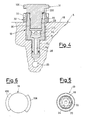
- each anchoring element 19 has a substantially cylindrical casing 20, threaded externally, from which there extends at its lower extremity an appendix 22 which is also cylindrical and with a smaller diameter.
- the supporting face 18 of pallet 5 has a plurality of cylindrical internally threaded holes 23 whose diameter corresponds to that of the casing 20 of the anchoring elements, and from the above holes there extend at their lower end respective cylindrical extensions 24 whose diameter corresponds to that of appendices 22 of the anchoring elements.
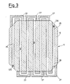
- each hole extension 24 communicates with a respectove channel 25, forming part of a network of horizontal channels within the base 16, which is illustrated in Fig. 3.
- Such channel network 25 communicates with a fluid feed hole 26 accessible from the lower face of base 16.
- the conformation of the above network, and thus the selection of the holes 23, 24 to be supplied with fluid, is variable in relation to the position of plugs 126 and of channelled plates 27 (not shown in Fig. 2), which close and connect, respectively, selected extremities accessible from the outside of the different channels 25.
- each hole 24 communicates with the outside by means of internal axial aligned passages 28 and 29 of the respective anchoring element 19.
- the upper passage 29 is internally and partially threaded, so that it may engage with a corresponding cylindrical tang 30 of a closing plug 31 having a gasket 220 and a head provided with radial protuberances 106 having the shape of a circular sector (Fig. 6) and terminates at its lower end with a hollow 34 having a six-cusp horizontal section with an underlying enlarged cylindrical support 21.
- Fig. 4 shows a clamping ring nut 32, which may be screwed on to the upper casing 20 of the anchoring element 19 outside the hole 23.
- the ring nut 32 is provided with radial notches 33 for the purpose of rotating the ring nut itself.
- FIG. 7 An example of a revolving table 7 suitable for positioning and clamping the pallet of Fig.s 2 to 5 is illustrated in Fig. 7.
- the above table comprises a base pedestal 35, on which there is hinged at 36 an inclinable part 37 operated (say, between 0° and 90°) by a hydraulic cylinder 38 hinged at 39 on pedestal 35 and at 40 on inclinable part 37.
- the inclinable part 37 supports by means of bearings 41 a rotatable part 42, which may be made to rotate by means of a pinion 43 engaged with a toothed crown 44 and may be clamped in predetermined angular positions (say, 0°, 90°, 180°, 270°) by means of a bolt 45 which may be inserted in circumferentially spaced hollows 46 of the rotatable part 42.
- An upper plate 47 provided with guides 48 complementary with guides 17 of pallet 5 has a lower tang 51 which engages with the rotatable part 42 in a vertically slidable way so as to operate the clamping of the pallet 5 above it. Clamping is executed by means of oil or other fluid suitably fed through channels 49 and 149 to a hydraulic cylinder 121 in which a piston 160 slides while constrained to tang 51.
- a further channel 50 feeds oil or other fluid to the upper hole 26 of pallet 5.
- a device 8 for testing the fastness of the clamping fixture is connected to the revolving table 7.
- the assembly thus constituted is illustrated in Fig. 8, wherein the testing device is shown constituted by an oleodynamic cylinder 52 with stem 53 suitable for pushing with force on the part mounted on pallet 5. Cylinder 52 is mounted on a supporting carriage 9 so that it may be displaced horizontally along a traverse 54 and vertically along guides 55.
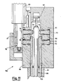
- FIG. 9 An example of a magazine 12 for modular components of clamping devices is shown in Fig. 9 and is constituted by two rows of caissons with sliding drawers 56 provided with handles 57.
- the robot 13 co-operates and includes an operating device 150 mounted in a vertically slidable way on a support 58, slidable horizontally along a traverse 59 in turn horizontally mobile along a guide 60.
- the operating device 150 comprises a tubular casing 61 made integral with a vertical bar 62 slidable in support 58 under the control of a vertical adjustment screw 120 operated by a coaxial motor 201 (Fig. 9).
- a tubular-shaped grasping organ 63 which terminates at its lower end with a pair of symmetrical protruding teeth 64 (Fig.s 10, 13 and 14) which may be engaged with the radial notches 33 of the clamping ring nuts 32 of anchoring elements 19 of pallet 5 (Fig.
- a finger-type grasping organ 65 which terminates at its lower end with an extremity 66 having a horizontal six-cusp star-shaped cross-section (Fig. 13), suitable for engaging with the six-cusp star-shaped hollow 34 of anchoring elements 19 of pallet 5 (Fig. 5).
- the finger-type grasping organ 65 is also vertically slidable inside the tubular-shaped grasping organ 63 under the control of a small oleodynamic piston 67 above it (Fig.s 10 and 11).
- the two grasping organs 63 and 65 are made to rotate by an operating mechanism included in an upper head 68 (Fig.s 9, 10 and 11) and controlled by an electric motor 69. More accurately, the above operating mechanism comprises a first toothed wheel 70 integral with the upper extremity of the tubular-shaped grasping organ 63 and provided with external teeth 72, as well as a freely-rotatable second toothed wheel 73 provided with internal teeth 74 and with external teeth 75.
- Fig.s 15 to 18 show, as an example, the method of operation of the grasping organs 63 and 65 for the withdrawal of a plug 31 from an anchoring element 19.
- the entire operating device 150 is lowered thanks to the screw 120 so that the teeth 64 are made to pass between one and the other of protuberances 106 of plug 31.
- the grasping organ 63 is made to rotate by motor 69 by means of rotor 78 (suitably lowered) and toothed wheel 70 (while toothed wheel 73 remains disengaged from rotor 78 and is locked by the small cylinders 81), so as to engage its teeth 64 with the protuberances 106 (Fig. 17) and then cause the unscrewing of plug 31.
- the finger-type grasping organ 65 is subsequently lowered until it presses with its lower extremity 66 against the top of plug 31 (Fig. 18). The latter is now held firmly and accurately by the two grasping organs 63 and 65 and may be transferred as required.
- Fig.s 19 to 24 there are shown some examples of modular components of clamping fixtures which robot 13 of Fig.s 9 to 14 is in a position of withdrawing from sliding drawers 56 of magazines 12, transferring and applying them to selected anchoring elements 19 of pallet 5, and vice versa.
- Fig.s 19 and 20 illustrate a modular component 82 for positioning and transversal alignment, which is formed by a solid cylindrical casing 83 provided with a lower threaded tang 84 having a diameter suitable for threading in the internal hole 29 of an anchoring element 19 of pallet 5 and with upper radial protuberances 85 which may engage with teeth 64 of tubular-shaped grasping organ 63 of robot 13 in the same way as protuberances 106 of plugs 31.
- a threaded radial hole 86 into which a commonly-found cap may be screwed down.
- An anular gasket 87 ensures hydraulic tightness when component 82 is applied to an anchoring element 19 of pallet 5.
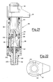
- Fig.s 21 and 22 illustrate a modular clamping element 88, which comprises a hollow cylindrical casing 89 provided with a lower threaded tang 90 having a diameter suitable for threading into the internal hole 29 of an anchoring element 19 of pallet 5.
- a clamping bracket 91 having protuberances 92 which may be engaged with teeth 64 of robot 13.
- From clamping bracket 91 there extends downward a cylindrical stem 93, which after an intermediate piston-shaped part 94 forms a part having a helical surface 95 engaged with cylindrical pins 96 integral with casing 89.
- a spring 97 resting against the thrust bearing 222 pushes upwards piston 94 and thus clamping bracket 91.
- a hole 98 obtained axially in a small cylindrical rod 223 passing through the threaded tang 90, the part with helical surface 95 and the piston 94 allows the feeding of oil or other fluid into an anular chamber 99 above piston 94 so as to overcome the force of spring 97 and arrange the component in the operative clamped position shown in Fig. 21.
- Fig.s 23 and 24 illustrate an intermediate modular component 100, which may be placed in any number between an anchoring element 19 and one or the other of the uppermost components 82 and 88.
- the component 100 is formed by an essentially cylindrical casing 101 provided with a lower externally-threaded tang 102 having a hydraulic gasket 233 and an upper axial hole 103 which is partially and internally threaded, suitable for screwing into internal hole 29 of an anchoring element 19 of pallet 5 and for receiving the lower threaded tang 84 of a positioning component 82 or the lower threaded tang 90 of a clamping component 88 or the tang 102 of an analogous intermediate component 100, respectively.
- Protuberances 104 analogous to those provided for in components 82, 88 or 100 and in plugs 31 are present in the upper extremity of cylindrical casing 101.
- An axial hole 105 passes through the entire component 100 to allow the passage of oil or other fluid toward the component 82, 88 or 100 above.
- the modular components 82, 88 and 100 of Fig.s 19 to 24, and many others which absolve reference and/or clamping functions and which have in common with those described the lower threaded tang and the upper protuberances so as to be compatible with the same pallet and with the same robot, are variably combinable with one another and with anchoring elements 19 suitably adjusted in height and in angular orientation to accomplish the positioning and the clamping of a rough piece 119 on pallet 5, as shown in Fig. 26.
- the above control centre comprises a programmable computer 107 provided with a console 108 which allows the introduction of data on the part of the operator 15 and the display of the computer's answering messages, as well as a printer 109 for printing the messages on paper.
- the computer 107 basically a normal computer available on the market, comprises a central processing unit (CPU) 110, a random access operating memory (RAM) III, a hard disk 112 on which the operating system and the station's operating program are stored, and a writing-reading unit 113 for magnetic disks.
- CPU central processing unit
- RAM random access operating memory
- hard disk 112 on which the operating system and the station's operating program are stored
- writing-reading unit 113 for magnetic disks.
- an electrical cabinet 114 which contains input data boards 115, output data boards 116, boards 117 for controlling the electrical axes of robot 13 and board 118 for controlling the oleodynamic axis of table 7.
- control centre 14 the operator 15 can program and cause to be executed the cycles of clamping assembly and disassembly of a rough piece on a pallet similar to that of Fig. 2.
- the movements of revolving table 7, of robot 13 and of testing device 8 to be executed on the occasion of the first assembly of a clamping fixture, are activated by the operator by means of suitably developed macroinstructions.
- a macroinstruction this is interpreted by the operating program of computer 107, stored on the hard disk 112 and moved to the operating RAM 111, and converted into individual movements in the execution sequence controlled by the CPU 110.
- the execution commands of these movements, at the output of the computer 107, are transformed or enhanced by the boards 115 or 116, or by the boards 117 and 118 when the movement in question refers to a numerically controlled axis.
- the operator places a sample rough piece 119 on the above supporting face of the pallet.
- the operator studies both the rough piece and the final piece to be accomplished and decides on the anchoring element 19 onto which to place the first component of the clamping fixture. He then orders robot 13 to remove the first plug 31 according to the way described with reference to Fig.s 15 to 18 and to adjust the height and angular orientation of the corresponding anchoring element.
- This latter operation is executed by engaging teeth 64 of tubular-shaped grasping organ 63 with notches 33 of locking ring nut 32, then again engaging the lower star-shaped extremity 66 of the finger-shaped grasping element 65 with the corresponding star-shaped cross-section 34 of internal hole 29 of the anchoring element to cause the latter's rotation and its consequent adjustment of height and of angular orientation, and lastly also tightening again ring nut 32 with teeth 64 of grasping organ 63.
- the operator orders robot 13 to open a selected drawer 56 of magazine 12 to withdraw a desired modular component 82, 88 or 100.
- the opening of the drawer is executed by engaging the finger-shaped grasping organ 65 of robot 13 with handle 57 of the selected drawer, which has a vertical hole suitable for receiving without any interference the lower extremity of said finger-shaped organ.
- robot 13 engages with teeth 64 the protuberances 85, 92 or 104 of the desired modular component 82, 88 or 100 and presses its top with extremity 66 pushed downward by piston 67 subsequently extracting the component from the drawer and translating it over the anchoring element 19 just prepared. When it reaches this point, the robot screws the component onto the anchoring element.
- the component thus applied is a positioning component 82 or a clamping component 88
- the operation on that anchoring element is finished and the operator can proceed to a subsequent anchoring.
- it is an intermediate component 100 the robot is ordered to repeat the operation with one or more other components 100 up to a last component 82 or 88. Component by component, the entire clamping fixture is thus assembled.
- the fluid present in channels 25 of the pallet overflows continuously toward the outside: this is useful so as to avoid the necessity of a final bleeder for the hydraulic circuit and to avoid the entry of dirt.
- the fluid used for this purpose is an emulsion of oil and water used in the machine tool, on which the pallet carrying the clamping fixture will be carried, to lubricate and cool the tool during chip removal.
- the use of the same fluid for the clamping and for the cooling functions eliminates all problems of tightness and unifies the recovery circuit for the fluid itself.
- the operator arranges a sample rough piece 119 on pallet 5 and executes its clamping by means of the clamping components 88 of the fixture itself. This is obtained by feeding the above fluid, directly or through hole 105 of an intermediate component 100, in axial hole 98 of the above clamping components until it reaches anular chamber 99, where it pushes piston 94 downward against the action of spring 97. Consequently, the clamping bracket 91 is lowered and, thanks to part 95 having a helical surface, it simultaneously rotates until it comes into close clamping contact with the upper face of the rough piece.
- the operator orients table 7 and translates the testing device 8, subsequently activating cylinder 52 so as to press with the latter's stem 53 onto the rough piece.
- a position sensor (not shown) he checks that the deformation of the clamping fixture and of the rough piece are within the desired limits.
- computer 107 has memorized all the instructions issued by the operator in sequence to the robot, to the revolving table and to the testing device and associates them with the piece's code. It memorizes them on hard disk 112 and on the magnetic disk which the operator has previously inserted in the writing-reading unit 113.
- the pallet itself is made to exit from the assembly station and is transferred to the conveyancing system 6, which moves it to a station for loading and unloading the rough pieces, which is provided with an oleodynamic coupling compatible with the inlet hole 26. This is where the loading of the different pieces to be machines occurs, as well as that of the sample already assembled, with respective ungrasping and grasping of the clamping fixture, and the loaded pallet is sent to be machined.
- the pallet which is by now empty and washed is made to return to station 1, where it is clamped on to the revolving table 7.
- robot 13 strips the pallet and automatically executes backwards all the operations previously executed for assembly and stored in the computer, placing as it goes along in the drawers of the magaine 12 the different dismantled components.
- a photocell system may be provided, which senses the height of the removed component or assembly and, if this is greater than that of the individual desired component, it orders the robot to move to a preset position where, manually or mechanically, the separation is executed of the components which are screwed together.
Landscapes
- Engineering & Computer Science (AREA)
- Mechanical Engineering (AREA)
- Manipulator (AREA)
- Automatic Assembly (AREA)
Abstract
Description
- The present invention relates to an assembly and disassembly station having an automatic programmable repetitive cycle for piece clamping fixtures on supporting pallets.
- In the world of machine tools "pallets" refers to plates on which pieces to be machined are clamped with suitable fixtures and which are moved from one or more holding stations to one or more machining, washing or measurement stations.
- The clamping fixtures utilized for said pallets are of the most diverse types and must be designed on a case by case basis in relation to the shape and size of the piece to be machined, to the features of the machine tool, to the machining accuracy required and to the quantity of pieces to be machined.
- Many attempts have been made to avoid having each clamping fixture redesigned from scratch and constructed specially.
- One of these is represented by the pallet described in the Italian patent application No. 22932 A/87 dated December 10, 1987, which provides for a plurality of anchoring elements adjustable in height and in angular orientation, with which it is possible to use modular components for the formation of the clamping fixture required on each occasion.
- In this way the number of different components in stock may be substantially reduced and the necessity is avoided of having to design specific components for the individual pieces to be machined.
- However, certain drawbacks remain, of which the main ones may be summarized as follows:
- the different operations for adjusting the pallet's anchoring elements, and for assemblying and disassemblying the clamping fixtures are still executed by hand;
- the cost of reassembly of a fixture which has already been used and disassembled is equal to that of first assembly;
- repetitive operations in the selection of the fixture's modular components, such as the composition of the lengths, the calculation of the clamping forces, the calculation of the deformations of the components, must be executed anew on each occasion. - The object of the present invention is now to accomplish an assembly and disassembly station for piece clamping fixtures on supporting pallets, which eliminates all the above mentioned drawbacks, making it possible to execute all the required operations within the scope of a programmable mechanized cycle, which may be repeated automatically on each occasion as desired.
- According to the invention such object is attained with an assembly and disassembly station for use with a pallet of the type provided with adjustable anchoring elements for components of clamping fixtures and is characterized in that it comprises a revolving table suitable for positioning and clamping an arriving pallet, a magazine for modular components of clamping fixtures, a robot operating between said revolving table and said magazine and provided with grasping organs for the adjustment of said anchoring elements of the pallet, for the grasping and transfer of said clamping fixture components and for their application to and separation from said anchoring elements, and a control centre with a computer controllable by a single operator.
- Preferably, the assembly and disassembly station according to the invention also comprises a device for testing the fastness of the clamping fixture, also under the control of the computer-equipped control centre.
- It appears obvious that the assembly and disassembly station according to the invention, completely mechanized, automated, repetitive, programmable and controllable by a single operator, offers great advantages with respect to current procedures, which are prevalently manual and require the intervention of several people.
- One possible embodiment of the present station is illustrated for greater clarity, but with no limiting intent, in the enclosed drawings, wherein:
- Fig. 1 shows the overall schematic plan view of an assembly and disassembly station according to the present invention;
- Fig. 2 shows a perspective view of an example of a pallet having adjustable anchoring elements, which may be used in connection with the assembly and disassembly station according to Fig. 1;
- Fig. 3 shows the pallet of Fig. 2 in a horizontal cross-sectional view taken along the line III-III of Fig. 2;
- Fig. 4 shows the enlarged detail, in an axial cross-sectional view, of an anchoring elements included in the above pallet, together with a corresponding closing plug;
- Fig. 5 shows said anchoring element in a plan view taken from above;
- Fig. 6 shows the above closing plug in a plan view taken from above;
- Fig. 7 shows in a partially sectioned side view a revolving table used in the station of Fig. 1 for positioning and clamping the pallet of Fig. 2;
- Fig. 8 shows a perspective view of the assembly of the table of Fig. 7 and of an associated device for testing the fastness of the clamping fixture, which may be utilized in the station of Fig. 1;
- Fig. 9 shows a perspective view of the assembly of a magazine for components of clamping fixtures and of a robot for the grasping, transfer and application of said components and for the adjustment of said anchoring elements, with which the station of Fig. 1 may be equipped;
- Fig. 10 shows the operating device of said robot in an axial cross-sectional view;
- Fig. 11 shows an enlarged detail of the above robot, again in an axial cross-sectional view;
- Fig. 12 shows said robot in an enlarged cross-sectional view taken along the line XII-XII of Fig. 10;
- Fig. 13 shows the grasping organs of said robot, seen in a plan view taken from below on an enlarged scale;
- Fig. 14 shows the enlarged detail of the lower extremity of one of the above grasping organs;
- Fig.s 15 to 18 show as an example, in a perspective view, the manner of operation of the robot's grasping organs on the closing plug of the pallet's anchoring elements;
- Fig.s 19 and 20 show a modular component of a clamping fixture, in a side view and in a plan view taken from above, respectively;
- Fig.s 21 and 22 show another modular component of a clamping fixture, in an axial cross-sectional view and in a plan view taken from above, respectively;
- Fig.s 23 and 24 show yet another modular component of a clamping fixture, in a plan view taken from above and in an axial cross-sectional view, respectively;
- Fig. 25 shows the diagram of the principles of a possible control centre which may be used in the station of Fig. 1;
- Fig. 26 shows in a perspective view the pallet of Fig. 2 in a condition equipped with a clamping fixture holding a rough piece to be machined.
- There is represented schematically in Fig. 1 an assembly and disassembly station according to the invention, which is accomplished within an
operating space 1 defined by sound-proof walls 2, which insulate it acoustically from the outside and which, thanks to a slight pressurization, protect it from machining dusts. Access gates for the operators are indicated with 3 and an air-tight entry and exit door with 4, operated automatically, for apallet 5 fed by a conveyancing system 6 to which it may be returned at the end of the operation. - Inside the
operating space 1 there is arranged a revolving table 7 for receiving, positioning and clamping thepallet 5 in an operating position for performing, as occasion demands, the assembly or disassembly of a clamping fixture. - Near the revolving table 7 there is arranged a
testing device 8 mounted on asupport 9, whose task it is to test the fastness of the piece at the end of the clamping fixture's assembly operation. - On the same side there is also provided a
jib crane 10 rotatable onpivot 11, used for raising a sample piece to be placed on the pallet as a reference during the first assembly of the clamping fixture. - On the opposite side there is on the other hand provided a caisson-
type magazine 12 for the modular components of the clamping fixtures. - Alongside and transversally to the magazine 12 a four-axis Cartesian robot may be moved, suitable for executing a multiplicity of functions which will be explained later.
- Lastly, there is provided a
control centre 14, equipped with a computer, controlled by anoperator 15. - An example of a
pallet 5 suitable for the assembly and disassembly station of Fig. 1, and in compliance with the above mentioned Italian patent application No. 22932 A/87, is shown in Fig.s 2 to 5, comprising abase 16 provided with standardizedsliding guides 17, which allow it to engage with usual complementary guides of the conveyancing system 6 as well as with, as will be seen later, corresponding guides of the revolving table 7. - In the illustrated
example pallet 5 is provided with a supportingface 18 for the piece to be machined and with the corresponding clamping fixture, but in more general terms it may also have two or four of them. - Whatever the number of the supporting faces, each of them is equipped with a plurality of
adjustable anchoring elements 19 for modular components of the clamping fixture. - As shown in Fig.s 4 and 5, each
anchoring element 19 has a substantiallycylindrical casing 20, threaded externally, from which there extends at its lower extremity anappendix 22 which is also cylindrical and with a smaller diameter. - In order to receive the
anchoring elements 19 the supportingface 18 ofpallet 5 has a plurality of cylindrical internally threadedholes 23 whose diameter corresponds to that of thecasing 20 of the anchoring elements, and from the above holes there extend at their lower end respectivecylindrical extensions 24 whose diameter corresponds to that ofappendices 22 of the anchoring elements. - The lower extremity of each
hole extension 24 communicates with arespectove channel 25, forming part of a network of horizontal channels within thebase 16, which is illustrated in Fig. 3.Such channel network 25 communicates with afluid feed hole 26 accessible from the lower face ofbase 16. The conformation of the above network, and thus the selection of theholes plugs 126 and of channelled plates 27 (not shown in Fig. 2), which close and connect, respectively, selected extremities accessible from the outside of thedifferent channels 25. - Returning to Fig.s 4 and 5, each
hole 24 communicates with the outside by means of internal axial alignedpassages respective anchoring element 19. - The
upper passage 29 is internally and partially threaded, so that it may engage with a correspondingcylindrical tang 30 of aclosing plug 31 having agasket 220 and a head provided withradial protuberances 106 having the shape of a circular sector (Fig. 6) and terminates at its lower end with a hollow 34 having a six-cusp horizontal section with an underlying enlargedcylindrical support 21. - Lastly, Fig. 4 shows a
clamping ring nut 32, which may be screwed on to theupper casing 20 of the anchoringelement 19 outside thehole 23. Thering nut 32 is provided withradial notches 33 for the purpose of rotating the ring nut itself. - An example of a revolving table 7 suitable for positioning and clamping the pallet of Fig.s 2 to 5 is illustrated in Fig. 7. The above table comprises a
base pedestal 35, on which there is hinged at 36 aninclinable part 37 operated (say, between 0° and 90°) by ahydraulic cylinder 38 hinged at 39 onpedestal 35 and at 40 oninclinable part 37. Theinclinable part 37 supports by means of bearings 41 arotatable part 42, which may be made to rotate by means of apinion 43 engaged with atoothed crown 44 and may be clamped in predetermined angular positions (say, 0°, 90°, 180°, 270°) by means of abolt 45 which may be inserted in circumferentially spacedhollows 46 of therotatable part 42. Anupper plate 47 provided withguides 48 complementary withguides 17 ofpallet 5 has alower tang 51 which engages with therotatable part 42 in a vertically slidable way so as to operate the clamping of thepallet 5 above it. Clamping is executed by means of oil or other fluid suitably fed throughchannels hydraulic cylinder 121 in which apiston 160 slides while constrained to tang 51. Afurther channel 50 feeds oil or other fluid to theupper hole 26 ofpallet 5. - As already said previously, a
device 8 for testing the fastness of the clamping fixture is connected to the revolving table 7. The assembly thus constituted is illustrated in Fig. 8, wherein the testing device is shown constituted by anoleodynamic cylinder 52 withstem 53 suitable for pushing with force on the part mounted onpallet 5.Cylinder 52 is mounted on a supportingcarriage 9 so that it may be displaced horizontally along atraverse 54 and vertically alongguides 55. - An example of a
magazine 12 for modular components of clamping devices is shown in Fig. 9 and is constituted by two rows of caissons with slidingdrawers 56 provided withhandles 57. - With the two rows of
drawers 56 therobot 13 co-operates and includes anoperating device 150 mounted in a vertically slidable way on asupport 58, slidable horizontally along atraverse 59 in turn horizontally mobile along aguide 60. - As better illustrated in Fig.s 10 to 14, the operating
device 150 comprises atubular casing 61 made integral with avertical bar 62 slidable insupport 58 under the control of avertical adjustment screw 120 operated by a coaxial motor 201 (Fig. 9). Inside thetubular casing 61, coaxially with it (Fig.s 10 and 12), there is rotatably housed a tubular-shaped graspingorgan 63, which terminates at its lower end with a pair of symmetrical protruding teeth 64 (Fig.s 10, 13 and 14) which may be engaged with theradial notches 33 of theclamping ring nuts 32 of anchoringelements 19 of pallet 5 (Fig. 4) and with theradial protuberances 106 of plugs 31 (Fig.s 4 and 6). Inside the above tubular-shaped graspingorgan 63, coaxially with it, there is in turn rotatably housed a finger-type grasping organ 65, which terminates at its lower end with anextremity 66 having a horizontal six-cusp star-shaped cross-section (Fig. 13), suitable for engaging with the six-cusp star-shaped hollow 34 of anchoringelements 19 of pallet 5 (Fig. 5). The finger-type grasping organ 65 is also vertically slidable inside the tubular-shaped graspingorgan 63 under the control of asmall oleodynamic piston 67 above it (Fig.s 10 and 11). - The two
grasping organs electric motor 69. More accurately, the above operating mechanism comprises a firsttoothed wheel 70 integral with the upper extremity of the tubular-shaped graspingorgan 63 and provided withexternal teeth 72, as well as a freely-rotatable secondtoothed wheel 73 provided withinternal teeth 74 and withexternal teeth 75. With the aboveinternal teeth 74 there engages an external set ofteeth 76 of the graspingorgan 65, while with the one and/or other of the aboveexternal teeth teeth 77 of arotor 78 made to rotate byelectric motor 69 and susceptible to be made to slide axially together with thesame motor 69 under the control of a three-positionhydraulic cylinder 79. Both the extremities of theteeth hydraulic cylinders toothed wheels - It appears evident that, according to the axial position of the
rotor 78,electric motor 69 is put into a position of rotating one or the other or both graspingorgans small cylinders organ 65 can also translate axially under the control of thesmall piston 67. - Fig.s 15 to 18 show, as an example, the method of operation of the grasping
organs plug 31 from an anchoringelement 19. With the tubular-shaped graspingorgan 63 suitably oriented at an angle, theentire operating device 150 is lowered thanks to thescrew 120 so that theteeth 64 are made to pass between one and the other ofprotuberances 106 ofplug 31. Once the lowered position of Fig. 16 has been attained, the graspingorgan 63 is made to rotate bymotor 69 by means of rotor 78 (suitably lowered) and toothed wheel 70 (whiletoothed wheel 73 remains disengaged fromrotor 78 and is locked by the small cylinders 81), so as to engage itsteeth 64 with the protuberances 106 (Fig. 17) and then cause the unscrewing ofplug 31. By means ofsmall piston 67, the finger-type grasping organ 65 is subsequently lowered until it presses with itslower extremity 66 against the top of plug 31 (Fig. 18). The latter is now held firmly and accurately by the two graspingorgans - In Fig.s 19 to 24 there are shown some examples of modular components of clamping fixtures which
robot 13 of Fig.s 9 to 14 is in a position of withdrawing from slidingdrawers 56 ofmagazines 12, transferring and applying them to selected anchoringelements 19 ofpallet 5, and vice versa. - Fig.s 19 and 20 illustrate a
modular component 82 for positioning and transversal alignment, which is formed by a solidcylindrical casing 83 provided with a lower threadedtang 84 having a diameter suitable for threading in theinternal hole 29 of an anchoringelement 19 ofpallet 5 and with upperradial protuberances 85 which may engage withteeth 64 of tubular-shaped graspingorgan 63 ofrobot 13 in the same way asprotuberances 106 ofplugs 31. In the upper part of the component there is also provided a threadedradial hole 86, into which a commonly-found cap may be screwed down. Ananular gasket 87 ensures hydraulic tightness whencomponent 82 is applied to an anchoringelement 19 ofpallet 5. - Fig.s 21 and 22 illustrate a
modular clamping element 88, which comprises a hollowcylindrical casing 89 provided with a lower threadedtang 90 having a diameter suitable for threading into theinternal hole 29 of an anchoringelement 19 ofpallet 5. Above thehollow casing 89 there is provided aclamping bracket 91 havingprotuberances 92 which may be engaged withteeth 64 ofrobot 13. From clampingbracket 91 there extends downward acylindrical stem 93, which after an intermediate piston-shapedpart 94 forms a part having ahelical surface 95 engaged withcylindrical pins 96 integral withcasing 89. Aspring 97 resting against thethrust bearing 222 pushes upwardspiston 94 and thus clampingbracket 91. Ahole 98 obtained axially in a smallcylindrical rod 223 passing through the threadedtang 90, the part withhelical surface 95 and thepiston 94 allows the feeding of oil or other fluid into ananular chamber 99 abovepiston 94 so as to overcome the force ofspring 97 and arrange the component in the operative clamped position shown in Fig. 21. - Fig.s 23 and 24 illustrate an intermediate
modular component 100, which may be placed in any number between an anchoringelement 19 and one or the other of theuppermost components component 100 is formed by an essentiallycylindrical casing 101 provided with a lower externally-threadedtang 102 having ahydraulic gasket 233 and an upperaxial hole 103 which is partially and internally threaded, suitable for screwing intointernal hole 29 of an anchoringelement 19 ofpallet 5 and for receiving the lower threadedtang 84 of apositioning component 82 or the lower threadedtang 90 of aclamping component 88 or thetang 102 of an analogousintermediate component 100, respectively.Protuberances 104 analogous to those provided for incomponents plugs 31 are present in the upper extremity ofcylindrical casing 101. Anaxial hole 105 passes through theentire component 100 to allow the passage of oil or other fluid toward thecomponent - The
modular components elements 19 suitably adjusted in height and in angular orientation to accomplish the positioning and the clamping of arough piece 119 onpallet 5, as shown in Fig. 26. - This, as well as the adjustment of anchoring
elements 19 ofpallet 5, is executed byrobot 13 in the manner which will be explained later and under the control ofcontrol centre 14 illustrated in Fig. 25. - The above control centre comprises a
programmable computer 107 provided with aconsole 108 which allows the introduction of data on the part of theoperator 15 and the display of the computer's answering messages, as well as aprinter 109 for printing the messages on paper. - The
computer 107, basically a normal computer available on the market, comprises a central processing unit (CPU) 110, a random access operating memory (RAM) III, ahard disk 112 on which the operating system and the station's operating program are stored, and a writing-reading unit 113 for magnetic disks. - To the
computer 107 there is connected anelectrical cabinet 114, which contains input data boards 115, output data boards 116,boards 117 for controlling the electrical axes ofrobot 13 and board 118 for controlling the oleodynamic axis of table 7. - Thanks to control
centre 14, theoperator 15 can program and cause to be executed the cycles of clamping assembly and disassembly of a rough piece on a pallet similar to that of Fig. 2. - The movements of revolving table 7, of
robot 13 and oftesting device 8 to be executed on the occasion of the first assembly of a clamping fixture, are activated by the operator by means of suitably developed macroinstructions. When the operator activates a macroinstruction, this is interpreted by the operating program ofcomputer 107, stored on thehard disk 112 and moved to theoperating RAM 111, and converted into individual movements in the execution sequence controlled by theCPU 110. The execution commands of these movements, at the output of thecomputer 107, are transformed or enhanced by the boards 115 or 116, or by theboards 117 and 118 when the movement in question refers to a numerically controlled axis. - Using such macroinstructions, once an
empty pallet 5 with all theanchoring elements 19 closed byplugs 31 has arrived on table 7 and has been clamped on it in the assembly position, the operator causes table 7 to be inclined and rotated until the pallet support face which is to receive the rough piece as well as the clamping fixture is horizontal and facing upward. - With the
jib crane 10 the operator then places a samplerough piece 119 on the above supporting face of the pallet. Using his experience, the operator studies both the rough piece and the final piece to be accomplished and decides on the anchoringelement 19 onto which to place the first component of the clamping fixture. He then ordersrobot 13 to remove thefirst plug 31 according to the way described with reference to Fig.s 15 to 18 and to adjust the height and angular orientation of the corresponding anchoring element. This latter operation is executed by engagingteeth 64 of tubular-shaped graspingorgan 63 withnotches 33 of lockingring nut 32, then again engaging the lower star-shapedextremity 66 of the finger-shaped graspingelement 65 with the corresponding star-shapedcross-section 34 ofinternal hole 29 of the anchoring element to cause the latter's rotation and its consequent adjustment of height and of angular orientation, and lastly also tightening againring nut 32 withteeth 64 of graspingorgan 63. - Subsequently the operator orders
robot 13 to open a selecteddrawer 56 ofmagazine 12 to withdraw a desiredmodular component organ 65 ofrobot 13 withhandle 57 of the selected drawer, which has a vertical hole suitable for receving without any interference the lower extremity of said finger-shaped organ. Once the drawer is open,robot 13 engages withteeth 64 theprotuberances modular component extremity 66 pushed downward bypiston 67 subsequently extracting the component from the drawer and translating it over the anchoringelement 19 just prepared. When it reaches this point, the robot screws the component onto the anchoring element. - If the component thus applied is a
positioning component 82 or aclamping component 88, the operation on that anchoring element is finished and the operator can proceed to a subsequent anchoring. If, however, it is anintermediate component 100, the robot is ordered to repeat the operation with one or moreother components 100 up to alast component - During assembly, when the presence of the
rough piece 119 onpallet 5 prevents the assembly of a component byrobot 13, the operator stops the robot and removes the rough piece from the pallet before starting up the robot again. When, on the other hand, the presence of the rough piece facilitates the operator's decision regarding the configuration of the clamping fixture, the operator stops the robot and places the rough piece on the pallet again. - Still during assembly, through the internal holes of anchoring
elements 19 with noplug 31, as well as through those ofintermediate components 100, the fluid present inchannels 25 of the pallet overflows continuously toward the outside: this is useful so as to avoid the necessity of a final bleeder for the hydraulic circuit and to avoid the entry of dirt. The fluid used for this purpose is an emulsion of oil and water used in the machine tool, on which the pallet carrying the clamping fixture will be carried, to lubricate and cool the tool during chip removal. The use of the same fluid for the clamping and for the cooling functions eliminates all problems of tightness and unifies the recovery circuit for the fluid itself. - Once the assembly of the fixture is completed, the operator arranges a sample
rough piece 119 onpallet 5 and executes its clamping by means of the clampingcomponents 88 of the fixture itself. This is obtained by feeding the above fluid, directly or throughhole 105 of anintermediate component 100, inaxial hole 98 of the above clamping components until it reachesanular chamber 99, where it pushespiston 94 downward against the action ofspring 97. Consequently, the clampingbracket 91 is lowered and, thanks topart 95 having a helical surface, it simultaneously rotates until it comes into close clamping contact with the upper face of the rough piece. - The
pallet 5 with therough piece 119 and the clamping fixture just assembled assumes, at this point, a configuration of the type shown in Fig. 26. - By means of further macroinstructions the operator orients table 7 and translates the
testing device 8, subsequently activatingcylinder 52 so as to press with the latter'sstem 53 onto the rough piece. With a position sensor (not shown) he checks that the deformation of the clamping fixture and of the rough piece are within the desired limits. - Meanwhile
computer 107 has memorized all the instructions issued by the operator in sequence to the robot, to the revolving table and to the testing device and associates them with the piece's code. It memorizes them onhard disk 112 and on the magnetic disk which the operator has previously inserted in the writing-reading unit 113. - In this way, if other analogous fixtures are required, the operator will key-in the piece's code and, under the control of the computer alone, the robot will once again perform the prior assembly and the necessary test. Storing on magnetic disk allows quick recovery of the instructions in case of breakages of the
hard disk 112. - Once the pallet has been provided with all the required fixtures and the corresponding tests have also been carried out, the pallet itself is made to exit from the assembly station and is transferred to the conveyancing system 6, which moves it to a station for loading and unloading the rough pieces, which is provided with an oleodynamic coupling compatible with the
inlet hole 26. This is where the loading of the different pieces to be machines occurs, as well as that of the sample already assembled, with respective ungrasping and grasping of the clamping fixture, and the loaded pallet is sent to be machined. - When all the pieces which are the same as that for which the clamping fixture has been designed have been machined and the fixture itself is thus no longer of any use, the pallet which is by now empty and washed is made to return to
station 1, where it is clamped on to the revolving table 7. Under the control ofcomputer 107,robot 13 strips the pallet and automatically executes backwards all the operations previously executed for assembly and stored in the computer, placing as it goes along in the drawers of themagaine 12 the different dismantled components. - It may happen that in an unscrewing operation of a part of a fixture having several superimposed components the robot takes away more than one of these components instead of just the uppermost one. To obviate this drawback, a photocell system may be provided, which senses the height of the removed component or assembly and, if this is greater than that of the individual desired component, it orders the robot to move to a preset position where, manually or mechanically, the separation is executed of the components which are screwed together.
- Each time that in the future there will be the requirement of preparing a pallet for machining a new lot of the same pieces or if several equally equipped pallets will be required simultaneously, the operator will recall the piece's code and the robot will automatically execute all the operations required for preparing the desired pallet with no need for further human actions or decisions. Testing with the
device 8 will automatically follow.
Claims (10)
Applications Claiming Priority (2)
| Application Number | Priority Date | Filing Date | Title |
|---|---|---|---|
| IT2305888 | 1988-12-22 | ||
| IT8823058A IT1227718B (en) | 1988-12-22 | 1988-12-22 | ASSEMBLY AND DISASSEMBLY STATION WITH AUTOMATIC AND REPETITIVE PROGRAMMABLE CYCLE FOR LOCKING EQUIPMENT OF PARTS ON SUPPORT PALLETS |
Publications (2)
| Publication Number | Publication Date |
|---|---|
| EP0375009A2 true EP0375009A2 (en) | 1990-06-27 |
| EP0375009A3 EP0375009A3 (en) | 1992-12-02 |
Family
ID=11203338
Family Applications (1)
| Application Number | Title | Priority Date | Filing Date |
|---|---|---|---|
| EP19890203095 Withdrawn EP0375009A3 (en) | 1988-12-22 | 1989-12-06 | Assembly and disassembly station having an automatic programmable repetitive cycle for piece clamping fixtures on supporting pallets |
Country Status (4)
| Country | Link |
|---|---|
| US (1) | US5046021A (en) |
| EP (1) | EP0375009A3 (en) |
| JP (1) | JPH02262922A (en) |
| IT (1) | IT1227718B (en) |
Cited By (4)
| Publication number | Priority date | Publication date | Assignee | Title |
|---|---|---|---|---|
| FR2763873A1 (en) * | 1997-05-30 | 1998-12-04 | Lionel Gaiani | Five-axis, numerically controlled machine tool esp. for aeronautical structures |
| WO2002011945A1 (en) * | 2000-08-09 | 2002-02-14 | Materialise, Naamloze Vennootschap | Method for manufacturing a supporting and/or reference construction |
| EP1314512A1 (en) * | 2001-11-26 | 2003-05-28 | Airbus France | Holding unit for the automatic machining of workpieces, and device and procedure incorporating such a device |
| JP2023055352A (en) * | 2021-10-06 | 2023-04-18 | 株式会社Fuji | Machine Tools |
Families Citing this family (5)
| Publication number | Priority date | Publication date | Assignee | Title |
|---|---|---|---|---|
| ES2079056T3 (en) * | 1990-12-18 | 1996-01-01 | Erowa Ag | AUTOMATIC MANUFACTURING PLANT. |
| EP0523889B1 (en) * | 1991-07-06 | 1996-12-27 | Daihen Corporation | Apparatus for controlling industrial robot to perform coordinated operation using teaching playback method and method thereof |
| JPH1011124A (en) * | 1996-06-20 | 1998-01-16 | Fanuc Ltd | Robot control device provided with robot back executing function |
| US6418861B1 (en) | 1999-11-18 | 2002-07-16 | Masco Corporation | Modular pallet construction |
| US12330255B2 (en) | 2022-04-07 | 2025-06-17 | Shelby Supply Co. | Clamping system and method for using same |
Family Cites Families (10)
| Publication number | Priority date | Publication date | Assignee | Title |
|---|---|---|---|---|
| US3884363A (en) * | 1973-09-13 | 1975-05-20 | Bendix Corp | Programmable universal transfer device |
| US3958740A (en) * | 1974-07-08 | 1976-05-25 | Dixon Automation, Inc. | Automatic component assembly machine and method relating thereto |
| US4260941A (en) * | 1975-10-28 | 1981-04-07 | Unimation, Inc. | Programmable automatic assembly system |
| US4321679A (en) * | 1979-01-08 | 1982-03-23 | Hitachi, Ltd. | Work setting system for manufacturing process |
| US4577284A (en) * | 1982-03-31 | 1986-03-18 | International Business Machines Corporation | Adaptive robot batch assembly system |
| US4543970A (en) * | 1983-02-21 | 1985-10-01 | Tokyo Shibaura Denki Kabushiki Kaisha | Automatic set-up system |
| CH661237A5 (en) * | 1984-12-19 | 1987-07-15 | Arcofil Sa | METHOD FOR AUTOMATICALLY LOADING WORKSTATIONS AND DEVICE FOR CARRYING OUT SAID METHOD. |
| US4694232A (en) * | 1985-07-16 | 1987-09-15 | Seiko Instruments & Electronics Ltd. | Robot controlling system |
| FR2606309B1 (en) * | 1986-11-06 | 1989-03-03 | Aerospatiale | SYSTEM FOR CLAMPING WORKPIECES AND INSTALLATION FOR PERFORMING OPERATIONS ON SAID WORKPIECES |
| IT1204693B (en) * | 1987-06-09 | 1989-03-10 | Guido Salvagnini | MACHINE TOOL FOR TURNING, MILLING, BORING, DRILLING AND WASHING WITH AUTONOMOUS GRIP OF THE PIECE IN PRODUCTION |
-
1988
- 1988-12-22 IT IT8823058A patent/IT1227718B/en active
-
1989
- 1989-12-06 EP EP19890203095 patent/EP0375009A3/en not_active Withdrawn
- 1989-12-20 JP JP1328568A patent/JPH02262922A/en active Pending
- 1989-12-21 US US07/454,421 patent/US5046021A/en not_active Expired - Fee Related
Cited By (6)
| Publication number | Priority date | Publication date | Assignee | Title |
|---|---|---|---|---|
| FR2763873A1 (en) * | 1997-05-30 | 1998-12-04 | Lionel Gaiani | Five-axis, numerically controlled machine tool esp. for aeronautical structures |
| WO2002011945A1 (en) * | 2000-08-09 | 2002-02-14 | Materialise, Naamloze Vennootschap | Method for manufacturing a supporting and/or reference construction |
| BE1013641A3 (en) * | 2000-08-09 | 2002-05-07 | Materialise Nv | Method for producing a support and / or reference construction. |
| EP1314512A1 (en) * | 2001-11-26 | 2003-05-28 | Airbus France | Holding unit for the automatic machining of workpieces, and device and procedure incorporating such a device |
| FR2832661A1 (en) * | 2001-11-26 | 2003-05-30 | Airbus France | GRIPPING UNIT FOR AUTOMATED PARTS MACHINING, AND MACHINING DEVICE AND METHOD INCLUDING SUCH A UNIT |
| JP2023055352A (en) * | 2021-10-06 | 2023-04-18 | 株式会社Fuji | Machine Tools |
Also Published As
| Publication number | Publication date |
|---|---|
| US5046021A (en) | 1991-09-03 |
| IT8823058A0 (en) | 1988-12-22 |
| JPH02262922A (en) | 1990-10-25 |
| EP0375009A3 (en) | 1992-12-02 |
| IT1227718B (en) | 1991-05-06 |
Similar Documents
| Publication | Publication Date | Title |
|---|---|---|
| US4679296A (en) | Machine tool | |
| US3052011A (en) | Machine tool with a mechanical cutting tool changer | |
| EP3747596B1 (en) | Multiple tensioning and measuring and / or adjusting station for tools and method for assembling/disassembling a tool in a tool holder | |
| US4499650A (en) | Automatic tool changer | |
| US4873756A (en) | Machine tool | |
| US4673076A (en) | Rotary shuttle for machine tools | |
| KR100217948B1 (en) | Tool change method of machining center and apparatus for performing the same | |
| US5342276A (en) | Turret punch press with a die exchanging device | |
| US3074147A (en) | Material working machine with multiple tool holder | |
| CA2477415C (en) | Movable arm activated tool changer for machine tool system, with special tool clip | |
| US4148400A (en) | Pallet locator and clamping assembly | |
| US5046021A (en) | Robotic assembly and disassembly station for removably clamping a succession of workpieces to a succession of support pallets | |
| JPS5949859B2 (en) | Tool storage and exchange methods and equipment for machine tools | |
| US3065530A (en) | Multiple motion processing machine | |
| US3930302A (en) | Machine tool with guard cover apparatus | |
| US4719691A (en) | Tool change mechanism for punch presses and the like | |
| CA2421518A1 (en) | Tool changer for removal and installation of tools in a machining centre | |
| JPH02163214A (en) | Method and device for making an electric motor using a pallet with removable workpiece holders | |
| US4813122A (en) | Machine tool | |
| JPS6218306B2 (en) | ||
| EP0011710B1 (en) | Machine tool with an automatic tool changer for single tools and multiple spindle toolheads, and a multiple spindle toolhead | |
| US3423812A (en) | Multiple spindle machine | |
| KR102749131B1 (en) | Tool magazine apparatus of machine tools | |
| US3316629A (en) | Machine tool tool changer | |
| US3949462A (en) | Removable attachment for automating milling machines |
Legal Events
| Date | Code | Title | Description |
|---|---|---|---|
| PUAI | Public reference made under article 153(3) epc to a published international application that has entered the european phase |
Free format text: ORIGINAL CODE: 0009012 |
|
| AK | Designated contracting states |
Kind code of ref document: A2 Designated state(s): AT BE CH DE ES FR GB IT LI NL SE |
|
| RAP1 | Party data changed (applicant data changed or rights of an application transferred) |
Owner name: SALVAGNINI S.P.A. |
|
| PUAL | Search report despatched |
Free format text: ORIGINAL CODE: 0009013 |
|
| AK | Designated contracting states |
Kind code of ref document: A3 Designated state(s): AT BE CH DE ES FR GB IT LI NL SE |
|
| 17P | Request for examination filed |
Effective date: 19930525 |
|
| STAA | Information on the status of an ep patent application or granted ep patent |
Free format text: STATUS: THE APPLICATION IS DEEMED TO BE WITHDRAWN |
|
| 18D | Application deemed to be withdrawn |
Effective date: 19940701 |