JP2023055352A - Machine Tools - Google Patents

Machine Tools Download PDF

Info

Publication number
JP2023055352A
JP2023055352A JP2021164653A JP2021164653A JP2023055352A JP 2023055352 A JP2023055352 A JP 2023055352A JP 2021164653 A JP2021164653 A JP 2021164653A JP 2021164653 A JP2021164653 A JP 2021164653A JP 2023055352 A JP2023055352 A JP 2023055352A
Authority
JP
Japan
Prior art keywords
work
slide member
workpiece
machine tool
cover
Prior art date
Legal status (The legal status is an assumption and is not a legal conclusion. Google has not performed a legal analysis and makes no representation as to the accuracy of the status listed.)
Granted
Application number
JP2021164653A
Other languages
Japanese (ja)
Other versions
JP7705773B2 (en
Inventor
大貴 渡辺
Daiki Watanabe
周一 平田
Shuichi Hirata
良彦 澤端
Yoshihiko Sawabata
康志 末次
Yasushi Suetsugu
Current Assignee (The listed assignees may be inaccurate. Google has not performed a legal analysis and makes no representation or warranty as to the accuracy of the list.)
Fuji Corp
Original Assignee
Fuji Corp
Priority date (The priority date is an assumption and is not a legal conclusion. Google has not performed a legal analysis and makes no representation as to the accuracy of the date listed.)
Filing date
Publication date
Application filed by Fuji Corp filed Critical Fuji Corp
Priority to JP2021164653A priority Critical patent/JP7705773B2/en
Publication of JP2023055352A publication Critical patent/JP2023055352A/en
Application granted granted Critical
Publication of JP7705773B2 publication Critical patent/JP7705773B2/en
Active legal-status Critical Current
Anticipated expiration legal-status Critical

Links

Images

Landscapes

  • Auxiliary Devices For Machine Tools (AREA)
  • Feeding Of Workpieces (AREA)

Abstract

To provide a machine tool which can reduce the size of a device by optimizing arrangement of a cover protrusion part of a device cover and a workpiece table.SOLUTION: A machine tool comprises: a workpiece holding device which holds a workpiece; a processing device which executes processing to the workpiece held by the workpiece holding device; a loader which executes delivery of the workpiece between the workpiece holding device and itself; a device cover which stores the workpiece holding device and the processing device; and a workpiece table on which the workpiece held by the loader can be placed. The device cover includes a cover protrusion part which protrudes to the outer side from the device cover and stores at least a portion of the workpiece holding device. The workpiece table comprises: a slide member which has a placement part on which the workpiece is placed; a table body part which holds the slide member in a slidable manner; and a frame member which holds the table body part with respect to an installation surface on which the machine tool is installed, and holds the table body part on the upper side of the cover protrusion part.SELECTED DRAWING: Figure 4

Description

本願は、工作機械におけるワークを載置するワーク置台に係わる技術に関するものである。 TECHNICAL FIELD The present application relates to a technique related to a work stand on which a work is placed in a machine tool.

下記特許文献1には、一方向に並ぶ複数のモジュールを備える加工機械ラインについて記載されている。特許文献1の加工機械ラインは、複数のモジュールの1つとして、ワーク置台モジュールを備えている。ワーク置台モジュールは、ワークの受け渡しや品質チェックのための仮置き台と、検測工程で不適切と判定された不適切ワークを貯め置きする不適切ワーク台を有している。また、ワーク置台モジュールは、作業者によってワークの取り出しが可能な構成になっている。 Patent Literature 1 listed below describes a processing machine line having a plurality of modules arranged in one direction. The processing machine line of Patent Literature 1 includes a workpiece table module as one of a plurality of modules. The workpiece table module has a temporary table for receiving and checking the quality of workpieces, and an inappropriate workpiece table for storing inappropriate workpieces determined to be inappropriate in the inspection process. Moreover, the work table module is configured so that the work can be taken out by the operator.

国際公開第WO2017/064813号International Publication No. WO2017/064813

ところで、上記したようなワーク置台は、ワークの搬送時間を短くする観点では、ワークを加工する加工装置からより近い位置に配置されることが好ましい。一方で、工作機械は、例えば、装置カバー内に収納する装置の全長が構造等の違いで長くなる場合、装置カバーの一部に、外側に突出したカバー突出部を設けて収納する必要が生じる。このため、カバー突出部と、ワーク置台の配置によっては装置が大型化する虞があった。 By the way, it is preferable that the work table as described above is arranged at a position closer to the processing device for processing the work from the viewpoint of shortening the time for transporting the work. On the other hand, in the machine tool, for example, when the total length of the device housed in the device cover is long due to a difference in structure, etc., it becomes necessary to provide a cover projecting portion that protrudes outward from a part of the device cover. . For this reason, there is a possibility that the size of the apparatus may increase depending on the arrangement of the cover protrusion and the work table.

本願は、上記の課題に鑑みてなされたものであり、装置カバーのカバー突出部と、ワーク置台の配置を最適化して装置の小型化を図れる工作機械を提供することを目的とする。 SUMMARY OF THE INVENTION The present invention has been made in view of the above problems, and an object thereof is to provide a machine tool capable of miniaturizing the apparatus by optimizing the arrangement of the cover protrusion of the apparatus cover and the workpiece table.

上記課題を解決するために、本明細書は、ワークを保持するワーク保持装置と、前記ワーク保持装置に保持された前記ワークに対する加工を実行する加工装置と、前記ワーク保持装置との間で前記ワークの受け渡しを実行するローダと、前記ワーク保持装置及び前記加工装置が収納された装置カバーと、前記ローダが把持した前記ワークを載置可能なワーク置台と、を備える工作機械であって、前記装置カバーは、前記装置カバーから外側へ突出し、前記ワーク保持装置の少なくとも一部が収納されるカバー突出部を有し、前記ワーク置台は、前記ワークが載置される載置部を有するスライド部材と、前記スライド部材をスライド可能に保持する置台本体部と、前記工作機械を設置する設置面に対して前記置台本体部を保持し、且つ前記カバー突出部の上方において前記置台本体部を保持するフレーム部材と、を有する、工作機械を開示する。 In order to solve the above-mentioned problems, the present specification provides a work holding device that holds a work, a processing device that performs machining on the work held by the work holding device, and a work holding device between the work holding device and the work holding device. A machine tool comprising: a loader for transferring a work; a device cover housing the work holding device and the processing device; and a work stand on which the work gripped by the loader can be placed, The device cover protrudes outward from the device cover and has a cover projecting portion in which at least part of the work holding device is accommodated, and the work table is a slide member having a placement portion on which the work is placed. a table main body portion that slidably holds the slide member; and a table main body portion that holds the table main body portion against an installation surface on which the machine tool is installed and that holds the table main body portion above the cover projecting portion. A machine tool is disclosed having a frame member.

本開示の工作機械によれば、フレーム部材によって置台本体部を、装置カバーから突出したカバー突出部の上方において保持する。このため、置台本体部とカバー突出部との干渉を避けつつ、ワーク保持装置や加工装置等にワーク置台を近づけることができる。これにより、ローダによって加工装置からワーク置台までワークを搬送する搬送時間を短縮できる。また、各装置間を近くに配置することで、装置全体の小型化を図ることが可能となる。 According to the machine tool of the present disclosure, the frame member holds the pedestal main body above the cover protrusion protruding from the device cover. Therefore, it is possible to bring the work stand closer to the work holding device, the processing device, etc. while avoiding interference between the stand main body and the cover projecting portion. As a result, the transport time for transporting the work from the processing device to the work table by the loader can be shortened. Also, by arranging the devices close to each other, it is possible to reduce the size of the entire device.

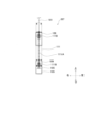
本実施形態の工作機械の正面図である。It is a front view of the machine tool of this embodiment. 本実施形態の工作機械の上面図である。It is a top view of the machine tool of this embodiment. 本体装置の一部を正面から見た図である。It is the figure which looked at a part of main unit from the front. ワーク置台の取り付け部分の正面図である。It is a front view of the attachment part of a work stand. 左から見たワーク置台の取り付け部分の側面図である。It is a side view of the attachment part of the work table seen from the left. ワーク置台を上方の後方側から見た斜視図である。It is the perspective view which looked at the workpiece|work stand from the upper back side. 置台本体部及びスライド部材の上面図である。It is a top view of a stand main body part and a slide member. プレート及び載置部を正面から見た図である。It is the figure which looked at the plate and the mounting part from the front. 付勢機構の背面図である。FIG. 4 is a rear view of the biasing mechanism; 別例のワーク置台を示す図である。It is a figure which shows the workpiece stand of another example.

以下、本願の工作機械を具体化した一実施形態について、図を参照しつつ詳しく説明する。図1及び図2に示すように、本実施形態の工作機械10は、本体装置11と、ローダ13と、入口装置15と、出口装置17と、ワーク置台(以下、「置台」という)18を備えている。尚、図2は、ローダ13の図示を省略している。また、図1及び図2は、各装置内に設けられた装置や機器(レール台25やフレーム部材62など)の一部を透過的に図示している。図3以降の図面においても同様である。また、以下の説明では、図1及び図2に示すように、工作機械10を正面から見た方向を基準として、機械幅方向であって装置の設置面19に水平な方向を左右方向、装置の設置面19に平行で左右方向に垂直な方向を前後方向、左右方向及び前後方向に垂直な方向を上下方向と称して説明する。 An embodiment embodying the machine tool of the present application will be described in detail below with reference to the drawings. As shown in FIGS. 1 and 2, a machine tool 10 of the present embodiment includes a main unit 11, a loader 13, an inlet device 15, an outlet device 17, and a work table (hereinafter referred to as "table") 18. I have. 2, illustration of the loader 13 is omitted. Also, FIGS. 1 and 2 transparently illustrate a part of devices and devices (rail base 25, frame member 62, etc.) provided in each device. The same applies to the drawings after FIG. 3 . Further, in the following description, as shown in FIGS. 1 and 2, with the direction of the machine tool 10 viewed from the front as a reference, the machine width direction and the direction horizontal to the installation surface 19 of the device is the left and right direction. The direction parallel to the installation surface 19 and perpendicular to the left-right direction is referred to as the front-rear direction, and the direction perpendicular to the left-right direction and the front-rear direction is referred to as the up-down direction.

(工作機械10の全体構成について)
工作機械10は、左右方向において左から順番に出口装置17、置台18、本体装置11、入口装置15の順に配置されている。本体装置11は、左右方向において工作機械10の中央に配置されている。本体装置11は、例えば、略直方体形状の装置カバー21を有する。装置カバー21の前面には、スライド扉22、操作部23が設けられている。スライド扉22の後方には、後述する加工装置55(図3参照)の加工スペースが設けられている。ユーザは、スライド扉22を開けることで加工スペースにアクセスでき、ワークWの確認、工具55B(図3参照)の交換などを行うことができる。操作部23は、例えば、タッチパネルやスイッチ等を備え、工作機械10に関する情報の表示や動作指示の受け付けなどを行う。
(Overall Configuration of Machine Tool 10)
The machine tool 10 has an exit device 17, a table 18, a main unit 11, and an entrance device 15 arranged in this order from the left in the left-right direction. The main unit 11 is arranged in the center of the machine tool 10 in the left-right direction. The main unit 11 has, for example, a substantially rectangular parallelepiped device cover 21 . A slide door 22 and an operation section 23 are provided on the front surface of the device cover 21 . A processing space for a processing device 55 (see FIG. 3), which will be described later, is provided behind the slide door 22 . The user can access the machining space by opening the slide door 22, and can check the workpiece W and replace the tool 55B (see FIG. 3). The operation unit 23 includes, for example, a touch panel and switches, and displays information about the machine tool 10 and receives operation instructions.

ローダ13は、入口装置15、本体装置11の主軸装置51(図3参照)、出口装置17の間でワークWの受け渡しを実行する。ローダ13は、例えば、ガントリ式のワーク搬送装置であり、本体装置11の上部に設けられたレール台25に沿って左右方向に可動部27を移動させる。例えば、ローダ13は、可動部27に内蔵された走行用モータ(図示略)の出力軸に固定されたピニオンを、レール台25に設けられた走行ラック(図示略)の歯部に係合させることで、可動部27をスライド移動させる。また、ローダ13は、可動部27を上下方向へ移動させる昇降装置(モータやラック機構など)を備えており、可動部27を上下方向に移動可能となっている。上記した走行用モータ、レール台25の走行ラック、昇降装置等は、本願の移動機構の一例である。可動部27の下端部には、一対のチャック機構29(図5参照)が取り付けられている。一対のチャック機構29の各々は、ワークWを挟持する爪などを備え、他の装置との間でワークWの受け渡しを実行する。 The loader 13 transfers the workpiece W between the inlet device 15 , the spindle device 51 (see FIG. 3) of the main body device 11 and the outlet device 17 . The loader 13 is, for example, a gantry-type work transfer device, and moves a movable portion 27 in the horizontal direction along a rail stand 25 provided on the upper portion of the main device 11 . For example, the loader 13 engages a pinion fixed to the output shaft of a running motor (not shown) built in the movable portion 27 with the teeth of a running rack (not shown) provided on the rail base 25. Thus, the movable portion 27 is slid. In addition, the loader 13 is provided with an elevating device (motor, rack mechanism, etc.) for moving the movable portion 27 in the vertical direction, so that the movable portion 27 can be moved in the vertical direction. The traveling motor, the traveling rack of the rail base 25, the lifting device, and the like described above are examples of the moving mechanism of the present application. A pair of chuck mechanisms 29 (see FIG. 5) are attached to the lower end of the movable portion 27 . Each of the pair of chuck mechanisms 29 has claws or the like for holding the work W, and transfers the work W to and from another device.

入口装置15は、ワークWを把持して左右方向へ移動する受け渡し装置31を備えている。受け渡し装置31は、扉33の後に設けられた受け取り位置において、例えば、ユーザや前工程の装置(図示略)からワークWを受け取ることができる。受け渡し装置31は
、受け取り位置から左方向へ移動し、左端の受け渡し位置においてローダ13のチャック機構29へワークWを受け渡す。入口装置15からローダ13のチャック機構29にワークWを受け渡す受け渡し位置には、右側フェンス35が取り付けられている。右側フェンス35は、工作機械10の前面を覆う装置カバーであり、装置カバー21の前面の右端部に固定され、入口装置15の一部を覆っている。右側フェンス35には、受け渡し位置にアクセス可能な扉37が設けられており、ローダ13と入口装置15のワークWの受け渡し状態を確認可能となっている。
The entrance device 15 includes a transfer device 31 that grips the work W and moves it in the left-right direction. The delivery device 31 can receive a work W from, for example, a user or a device (not shown) in a previous process at a receiving position provided behind the door 33 . The delivery device 31 moves leftward from the receiving position and delivers the work W to the chuck mechanism 29 of the loader 13 at the leftmost delivery position. A right fence 35 is attached at a transfer position where the workpiece W is transferred from the entrance device 15 to the chuck mechanism 29 of the loader 13 . The right fence 35 is a device cover that covers the front of the machine tool 10 , is fixed to the right end of the front of the device cover 21 , and partially covers the entrance device 15 . The right fence 35 is provided with a door 37 that allows access to the transfer position, so that the transfer state of the work W between the loader 13 and the entrance device 15 can be checked.

出口装置17は、ワークWを把持して移動する受け取り装置41を備えている。尚、以下の出口装置17の説明では、上記した入口装置15と同様の内容についてはその説明を適宜省略する。受け取り装置41は、扉43の後方の受け渡し位置において、後工程の装置(図示略)等にワークWを受け渡す。受け取り装置41は、左側フェンス45に前面を覆われた受け取り位置でローダ13のチャック機構29からワークWを受け取る。左側フェンス45は、工作機械10の前面を覆う装置カバーであり、装置カバー21の前面の左端部に固定され、出口装置17の一部を覆っている。左側フェンス45には、受け取り位置にアクセス可能な扉47が設けられている。 The exit device 17 includes a receiving device 41 that grips and moves the work W. As shown in FIG. In the explanation of the outlet device 17 below, the explanation of the same content as that of the inlet device 15 will be omitted as appropriate. The receiving device 41 delivers the workpiece W to a post-process device (not shown) or the like at a delivery position behind the door 43 . The receiving device 41 receives the work W from the chuck mechanism 29 of the loader 13 at a receiving position where the front surface is covered with the left fence 45 . The left fence 45 is a device cover that covers the front of the machine tool 10 , is fixed to the front left end of the device cover 21 , and partially covers the exit device 17 . The left fence 45 is provided with a door 47 that allows access to the receiving position.

また、左側フェンス45は、右側フェンス35に比べて左右方向の幅が長くなっている。左右方向における扉47と本体装置11との間には、置台18が配置されている。置台18は、後述するフレーム部材62等の装置の一部が前方側に配置された左側フェンス45によって覆われ正面からは見えなくなっている。尚、図1ではフレーム部材62を透過的に図示している。また、置台18は、左側フェンス45に設けられた開口45Aからスライド部材63の前面カバー83(図7参照)を露出させており、スライド部材63を前方側の下方に向かって引き出し可能となっている。置台18の詳細については後述する。また、図2に示すように、本体装置11の後方には、クーラントを供給する潤滑装置16などが配置されている。 Also, the left fence 45 has a longer width in the left-right direction than the right fence 35 . A stand 18 is arranged between the door 47 and the main unit 11 in the horizontal direction. The pedestal 18 is hidden from view from the front by being covered by a left fence 45 in which a part of the device such as a frame member 62, which will be described later, is arranged on the front side. 1, the frame member 62 is transparently illustrated. In addition, the table 18 exposes a front cover 83 (see FIG. 7) of the slide member 63 through an opening 45A provided in the left fence 45, so that the slide member 63 can be pulled out forward and downward. there is The details of the mounting table 18 will be described later. Further, as shown in FIG. 2, a lubricating device 16 for supplying coolant and the like are arranged behind the main unit 11 .

(本体装置11について)
図3は、本体装置11の正面の一部を示している。尚、図3は、装置カバー21の後方に配置された主軸装置51等を透過的に図示している。図3に示すように、本体装置11は、主軸装置51、心押し装置53、加工装置55を備えている。主軸装置51は、スライド扉22を開けた加工スペースに配置されており、ワークWを保持して左右方向に沿った軸心を中心にワークWを回転させるワーク保持装置である。本実施形態のワークWは、例えば、一方向に長い円柱形状の部材であり(図8参照)、主軸装置51の加工位置(図3に示す位置)に保持された状態において、軸方向が主軸装置51の軸心に沿った状態となっている。ワークWは、例えば、図3における右側に開口を有し、開口から所定の深さの凹部77(図8参照)が軸方向に形成されている。主軸装置51には、ワークWの長手方向に沿って形成された凹部51Aが設けられている。
(Regarding main unit 11)
FIG. 3 shows a part of the front of the main unit 11. As shown in FIG. 3 transparently illustrates the spindle device 51 and the like arranged behind the device cover 21. As shown in FIG. As shown in FIG. 3 , the main unit 11 includes a spindle device 51 , a tailstock device 53 and a processing device 55 . The main shaft device 51 is arranged in the processing space with the slide door 22 opened, and is a work holding device that holds the work W and rotates the work W around an axis extending in the left-right direction. The workpiece W of the present embodiment is, for example, a cylindrical member that is long in one direction (see FIG. 8), and when held at the machining position (position shown in FIG. 3) of the spindle device 51, the axial direction is the spindle. It is in a state along the axis of the device 51 . The work W has, for example, an opening on the right side in FIG. 3, and a recess 77 (see FIG. 8) having a predetermined depth from the opening is formed in the axial direction. The spindle device 51 is provided with a concave portion 51A formed along the longitudinal direction of the work W. As shown in FIG.

心押し装置53は、ローダ13(図1参照)によって加工スペースに搬入されたワークWを、主軸装置51へ押し込む装置である。心押し装置53は、ワークWの凹部77(図8参照)に挿入され、右側から左側へワークWを押し出して、主軸装置51の凹部51A内へワークWを押し込み、ワークWを加工位置に配置する。 The tail pushing device 53 is a device that pushes the work W carried into the machining space by the loader 13 (see FIG. 1) into the spindle device 51 . The tailstock device 53 is inserted into the recessed portion 77 (see FIG. 8) of the work W, pushes the work W from the right side to the left side, pushes the work W into the recessed portion 51A of the spindle device 51, and places the work W at the machining position. do.

加工装置55は、刃物台55Aに取り付けられた工具55BによってワークWに対する加工を実行する。加工装置55は、駆動装置(図示略)によって刃物台55Aの位置を変更され、ワークWに対する工具55Bの位置を変更される。加工装置55は、例えば、ワークWの基端部(心押し装置53側)の外周面に対して工具55Bによって溝削り加工を実行する。 The machining device 55 carries out machining on the workpiece W using a tool 55B attached to the tool post 55A. In the processing device 55, the position of the tool post 55A is changed by a driving device (not shown), and the position of the tool 55B with respect to the work W is changed. The processing device 55, for example, performs grooving on the outer peripheral surface of the base end portion of the work W (on the side of the tailstock device 53) using a tool 55B.

また、主軸装置51は、装置の左側に押し出し装置51Bを備えている。押し出し装置51Bは、主軸装置51からワークWを取り出す際に、凹部51AからワークWを押し出す装置である。押し出し装置51Bは、ワークWの先端に形成された凹部78(図8参照)に押し出し部材を挿入し、右方向(主軸装置51から出る方向)へワークWを押し出す。ローダ13は、押し出し装置51Bによって右側に押し出されたワークWを受け取って出口装置17や置台18まで搬送する。 Further, the spindle device 51 is provided with a pushing device 51B on the left side of the device. The push-out device 51B is a device that pushes out the work W from the recess 51A when the work W is taken out from the spindle device 51 . The push-out device 51B inserts a push-out member into a recess 78 (see FIG. 8) formed at the tip of the work W, and pushes out the work W to the right (the direction out of the spindle device 51). The loader 13 receives the work W pushed out to the right side by the pushing device 51B and conveys it to the exit device 17 and the mounting table 18 .

また、装置カバー21の左側面21Bには、カバー突出部21Aが設けられている。カバー突出部21Aは、左側面21Bから左方向、即ち、装置幅方向の外側へ突出した箱形形状をなしている。カバー突出部21Aには、押し出し装置51Bの一部が収納されている。従って、本実施形態のカバー突出部21Aには、ワークWを保持する主軸装置51の一部が収納されている。 A left side surface 21B of the device cover 21 is provided with a cover projecting portion 21A. The cover projecting portion 21A has a box-like shape projecting leftward from the left side surface 21B, that is, outward in the device width direction. A part of the pushing device 51B is accommodated in the cover projecting portion 21A. Therefore, part of the spindle device 51 that holds the workpiece W is accommodated in the cover projecting portion 21A of the present embodiment.

ここで、本実施形態のように長尺のワークWを取り扱う場合など、主軸装置51のような装置カバー21に収納される装置について、その装置の全長が長くなる場合がある。本実施形態のように押し出し装置51Bを主軸装置51に配置する場合の他、例えば、クーラントを供給するインジューサーのポートを主軸装置51の軸心に沿って並べる場合や、ワークWを保持するチャックを軸心に沿って並べる場合など、様々な要因で装置の全長が長くなる可能性がある。このような場合に、カバー突出部21Aを設けずに、全長の長い装置の全体を装置カバー21内に収納しようとすると、装置カバー21の大型化、即ち、本体装置11の大型化を招く虞がある。そこで、全長の長い装置の一部、例えば、押し出し装置51Bを収容する部分だけを突出させたカバー突出部21Aを設けることで、装置カバー21の大型化を抑制することができる。そして、本実施形態の工作機械10は、このカバー突出部21Aと置台18の配置を最適化することで、工作機械10全体の更なる小型化を図っている。 Here, when a long workpiece W is handled as in the present embodiment, the total length of a device such as the spindle device 51 that is housed in the device cover 21 may become long. In addition to arranging the extrusion device 51B in the spindle device 51 as in the present embodiment, for example, when the ports of the inducer that supplies coolant are arranged along the axis of the spindle device 51, or when the chuck holding the work W is arranged The total length of the device may increase due to various factors such as arranging the devices along the axis. In such a case, if the entire device having a long overall length is to be accommodated in the device cover 21 without providing the cover protrusion 21A, the device cover 21 may be enlarged, that is, the main device 11 may be enlarged. There is Therefore, by providing a cover projecting portion 21A that protrudes only from a portion of the device having a long overall length, for example, a portion that accommodates the pushing device 51B, it is possible to suppress the device cover 21 from increasing in size. The machine tool 10 of the present embodiment optimizes the arrangement of the cover protrusion 21A and the mounting table 18, thereby further miniaturizing the machine tool 10 as a whole.

(置台18について)
次に、置台18について説明する。図4~図6に示すように、置台18は、置台本体部61、フレーム部材62、スライド部材63を有している。尚、図5及び後述する図7は、後述する置台本体部61内に収納される収納位置P1まで押し込んだスライド部材63と、ワークWを取り出し可能な取り出し位置P2まで引き出したスライド部材63の両方を図示している。収納位置P1は、例えば、後述する第1ロック部材93によってスライド位置を保持され、スライド部材63の前面カバー83によって左側フェンス45の開口45Aを閉じた位置である。取り出し位置P2は、例えば、第2ロック部材94によって位置を保持され、載置部75の後面カバー75Cによって開口45Aを閉じた位置である。
(Regarding the stand 18)
Next, the table 18 will be described. As shown in FIGS. 4 to 6, the table 18 has a table body 61, a frame member 62, and a slide member 63. As shown in FIGS. 5 and FIG. 7, which will be described later, both the slide member 63 pushed in to the storage position P1 stored in the table main body 61 described later and the slide member 63 pulled out to the take-out position P2 from which the workpiece W can be taken out are shown. is illustrated. The retracted position P1 is, for example, a position where the slide position is held by a first lock member 93 (to be described later) and the opening 45A of the left fence 45 is closed by the front cover 83 of the slide member 63 . The take-out position P2 is, for example, a position held by the second locking member 94 and the opening 45A is closed by the rear cover 75C of the placing section 75. As shown in FIG.

置台本体部61は、例えば、上下方向に薄く、左右方向に所定の幅を有し、前後方向に長い長方形の略板状の部材である。フレーム部材62は、例えば、4本の柱部材65と、付勢機構67を有している。4本の柱部材65の各々は、左右方向において所定の幅を有し、上下方向に長い板状の金属部材であり、横板66(図4参照)等により互いに連結されている。4本の柱部材65の下端部は、アンカー69によって設置面19に固定されている。 The table main body 61 is, for example, a substantially rectangular plate-shaped member that is thin in the vertical direction, has a predetermined width in the horizontal direction, and is long in the front-rear direction. The frame member 62 has, for example, four pillar members 65 and an urging mechanism 67 . Each of the four pillar members 65 is a plate-like metal member having a predetermined width in the horizontal direction and elongated in the vertical direction, and is connected to each other by a horizontal plate 66 (see FIG. 4) or the like. The lower ends of the four column members 65 are fixed to the installation surface 19 by anchors 69 .

4本の柱部材65のうち、2本の柱部材65は、カバー突出部21Aの前方に配置され、残りの2本の柱部材65は、カバー突出部21Aの後方に配置されている。前方側と後方側の各々に配置された2本の柱部材65は、左右方向において、所定の隙間を設けて配置されている。また、後方側の2本の柱部材65のうち右側の柱部材65は、ブラケット64(図4及び図5参照)によってローダ13の支柱(図示略)と固定されている。ブラケット64は、例えば、2枚のL字型の金属部材を有し、柱部材65と支柱の各々に固定
したL字の金属部材を互いに固定することで、ローダ13の支柱に対して置台18を固定する。置台本体部61は、4本の柱部材65の上端に固定され、カバー突出部21Aの上方に配置されている。置台本体部61は、後方(工作機械10の背面)から前方に向かうに従って下方へ傾斜した状態で柱部材65によって保持され、傾斜方向71(図5参照)に傾いている。従って、フレーム部材62は、工作機械10の設置面19に対して置台本体部61を保持し、且つカバー突出部21Aの上方において置台本体部61を保持する。尚、置台本体部61の側方には、置台18へのワークWの進入や退出を検出するワークセンサ59が設けられている(図4参照)。また、以下の説明では、傾斜方向71における上方側(図5における左側)を基端側、下方側(図5における右側)を先端側と称して説明する。
Of the four pillar members 65, two pillar members 65 are arranged in front of the cover protrusion 21A, and the remaining two pillar members 65 are arranged behind the cover protrusion 21A. The two pillar members 65 arranged on each of the front side and the rear side are arranged with a predetermined gap in the left-right direction. Also, the right column member 65 of the two rear column members 65 is fixed to a support (not shown) of the loader 13 by a bracket 64 (see FIGS. 4 and 5). The bracket 64 has, for example, two L-shaped metal members, and the column member 65 and the L-shaped metal members fixed to each of the columns are fixed to each other so that the table 18 can be attached to the column of the loader 13 . fixed. The stand body portion 61 is fixed to the upper ends of the four pillar members 65 and arranged above the cover projecting portion 21A. The table main body 61 is held by a column member 65 in a state of being inclined downward from the rear (back surface of the machine tool 10) toward the front, and is inclined in an inclination direction 71 (see FIG. 5). Therefore, the frame member 62 holds the table body portion 61 against the installation surface 19 of the machine tool 10 and holds the table body portion 61 above the cover projecting portion 21A. A work sensor 59 for detecting the entry and exit of the work W to and from the stand 18 is provided on the side of the stand main body 61 (see FIG. 4). Further, in the following description, the upper side (left side in FIG. 5) in the inclination direction 71 is referred to as the proximal side, and the lower side (right side in FIG. 5) is referred to as the distal side.

図6に示すように、置台本体部61の上面には、スライド部材63をスライド可能に保持するスライド機構73が設けられている。スライド機構73は、例えば、ベアリングを用いたスライド装置であり、レール73Aと、レール73Aに対してスライド移動可能なテーブル73Bを有し、テーブル73Bに設けられたベアリング(ボールベアリングなど)によってテーブル73Bを傾斜方向71へスライド移動させる。 As shown in FIG. 6 , a slide mechanism 73 that slidably holds the slide member 63 is provided on the upper surface of the table main body 61 . The slide mechanism 73 is, for example, a slide device using bearings, and has a rail 73A and a table 73B that can slide relative to the rail 73A. is slid in the tilt direction 71 .

図6及び図7に示すように、テーブル73Bは、スライド部材63における後端の下面に取り付けられ、収納位置P1にスライド部材63を配置した状態において、置台本体部61の基端側に配置される。また、置台本体部61の先端側には、2つの回転部材70が設けられている。2つの回転部材70は、左右方向における置台本体部61の両端部分に設けられ、スライド部材63を上に載せた状態で回転可能となっている。スライド部材63は、基端側をテーブル73Bに支持され、先端部側を回転部材70に支持され、傾斜方向71へスライド移動する。これにより、スライド部材63は、置台本体部61から傾斜方向71の先端側へ引き出し可能となっている。そして、カバー突出部21Aの上方に置台本体部61を配置し、装置カバー21の左側面21Bと置台18とを近接した位置に配置しつつ、スライド部材63(ワークW)を引き出した取り出し位置P2を収納位置P1よりも低くすることができる。即ち、取り出し位置P2におけるワークWの設置面19からの高さを低くできる。このため、置台18の位置を左側面21Bに近づけて工作機械10の小型化を図りつつ、ユーザによるワークWの出し入れの利便性を向上できる。尚、置台本体部61及びスライド部材63は、傾斜しない構成でも良い。例えば、フレーム部材62は、置台本体部61及びスライド部材63を設置面19に対して水平な状態でカバー突出部21Aの上方で保持しても良い。 As shown in FIGS. 6 and 7, the table 73B is attached to the lower surface of the rear end of the slide member 63, and is arranged on the base end side of the table main body 61 when the slide member 63 is arranged at the storage position P1. be. Further, two rotating members 70 are provided on the tip side of the table body portion 61 . The two rotating members 70 are provided at both end portions of the table main body 61 in the left-right direction, and are rotatable with the slide member 63 placed thereon. The slide member 63 is supported by a table 73B at its proximal end and supported by the rotary member 70 at its distal end, and slides in the tilt direction 71 . As a result, the slide member 63 can be pulled out from the table main body 61 toward the tip side in the inclination direction 71 . Then, the pedestal main body 61 is arranged above the cover projecting portion 21A, and the left side 21B of the device cover 21 and the pedestal 18 are arranged in close proximity to each other, and the slide member 63 (workpiece W) is pulled out to the take-out position P2. can be lower than the storage position P1. That is, the height of the workpiece W from the installation surface 19 at the take-out position P2 can be reduced. Therefore, the machine tool 10 can be downsized by moving the table 18 closer to the left side surface 21B, and the user's convenience of loading and unloading the work W can be improved. Note that the pedestal main body 61 and the slide member 63 may be configured so as not to be tilted. For example, the frame member 62 may hold the table main body 61 and the slide member 63 horizontally with respect to the installation surface 19 above the cover projecting portion 21A.

図5に示すように、カバー突出部21Aの上部には、傾斜方向71に傾斜した置台本体部61及びスライド部材63の位置や形状に合わせて切り欠き部21Cが形成されている。置台本体部61は、例えば、前後方向におけるカバー突出部21Aの略中央においてカバー突出部21Aの上面と略同一高さとなっており、カバー突出部21Aと接触又はカバー突出部21Aから僅かに離間している。切り欠き部21Cは、前後方向におけるカバー突出部21Aの中央から前端まで形成された傾斜面である。切り欠き部21Cは、置台本体部61の傾斜角よりも大きい角度で下方側へ傾斜しており、前後方向のカバー突出部21Aの中央から前方に行くに従って、上下方向における置台本体部61との間の距離が長くなっている。換言すれば、フレーム部材62は、前後方向のカバー突出部21Aの中央部を除き、カバー突出部21Aの上面や切り欠き部21Cから置台本体部61を離間した状態で保持している。このような構成では、本体装置11を配置した後に置台18を配置する場合に、フレーム部材62を設置した後、設置したフレーム部材62の上に置台本体部61を載せて固定する際、置台本体部61とカバー突出部21Aの干渉を抑制しつつ置台本体部61を取り付けることができる。置台本体部61の取り外し作業においても同様である。このため、置台18の着脱作業の作業負担を軽減することができる。 As shown in FIG. 5, a notch portion 21C is formed in the upper portion of the cover projecting portion 21A so as to match the positions and shapes of the table main body portion 61 and the slide member 63 which are inclined in the inclination direction 71. As shown in FIG. The stand main body 61 is, for example, approximately the same height as the upper surface of the cover projection 21A at approximately the center of the cover projection 21A in the front-rear direction, and is in contact with the cover projection 21A or is slightly separated from the cover projection 21A. ing. The notch portion 21C is an inclined surface formed from the center to the front end of the cover projecting portion 21A in the front-rear direction. The notch portion 21C is inclined downward at an angle larger than the inclination angle of the stand main body portion 61, and is inclined to the stand main body portion 61 in the vertical direction as it goes forward from the center of the front-rear direction cover projecting portion 21A. the distance between them is getting longer. In other words, the frame member 62 holds the table main body 61 apart from the upper surface of the cover protrusion 21A and the notch 21C except for the front-rear central portion of the cover protrusion 21A. With such a configuration, when the table 18 is arranged after the main unit 11 is arranged, when the table main body 61 is placed on the frame member 62 and fixed after the frame member 62 is installed, the table main body 61 is fixed. The stand body portion 61 can be attached while suppressing interference between the portion 61 and the cover projecting portion 21A. The same applies to the work of removing the stand body portion 61 . Therefore, it is possible to reduce the work load of attaching and detaching the table 18 .

図6及び図7に示すように、スライド部材63には、ワークWを載置可能な載置部75が設けられている。載置部75は、傾斜方向71におけるスライド部材63の基端側(図5の左側)の上面に取り付けられている。図8は、ワークWを載置した載置部75を後述するプレート81の位置に配置し、正面から見た状態を示している。図8に示すように、載置部75は、底板75Aと、3つの支持部材75Bを有している。底板75Aは、板状の金属部材であり、スライド部材63の上面に固定されている。底板75Aの上面には、3つの支持部材75Bが左右方向に並んで配置されている。支持部材75Bは、例えば、複数の金属部材を接続して固定されており、ワークWの外周形状に合わせた溝(図示略)が上端部に形成されている。3つの支持部材75Bは、この溝に上方から挿入されたワークWを下方から支持する。工作機械10は、例えば、軸方向の長さが異なるワークWを加工可能となっている。工作機械10は、ワークWの軸方向の長さに応じて、3つの支持部材75Bのうち、例えば、2つ(図8の右側2つ)の支持部材75Bのみを使用する場合や、3つの支持部材75Bを全て使用する場合がある。尚、図7は、取り出し位置P2の底板75Aや支持部材75Bの図示を省略している。 As shown in FIGS. 6 and 7, the slide member 63 is provided with a placement portion 75 on which the workpiece W can be placed. The mounting portion 75 is attached to the upper surface of the slide member 63 on the base end side (left side in FIG. 5) in the tilt direction 71 . FIG. 8 shows a state in which the placement section 75 on which the workpiece W is placed is arranged at the position of a plate 81 to be described later and viewed from the front. As shown in FIG. 8, the mounting section 75 has a bottom plate 75A and three support members 75B. The bottom plate 75A is a plate-like metal member and is fixed to the upper surface of the slide member 63. As shown in FIG. Three support members 75B are arranged side by side in the left-right direction on the upper surface of the bottom plate 75A. The support member 75B is, for example, fixed by connecting a plurality of metal members, and a groove (not shown) matching the outer peripheral shape of the work W is formed in the upper end portion. The three support members 75B support from below the workpiece W inserted into the groove from above. The machine tool 10 can, for example, process workpieces W having different lengths in the axial direction. Of the three support members 75B, the machine tool 10 may use, for example, only two support members 75B (two on the right side in FIG. 8) or three In some cases, all of the support members 75B are used. 7 omits illustration of the bottom plate 75A and the support member 75B at the take-out position P2.

図5及び図8に示すように、載置部75の底板75Aは、傾斜方向71に傾斜したスライド部材63に対して水平な状態で固定されている。載置部75は、スライド部材63を傾斜方向71にスライド移動させる前後において、支持部材75Bによって支持したワークWを水平(前後方向及び左右方向と平行)な状態で保持する。支持部材75Bに支持されたワークWは、例えば、軸方向が左右方向に沿った状態で保持され、スライド移動する。これにより、スライド部材63を傾斜させた構成であっても、スライド部材63の引き出し動作においてワークWの脱落や転がりが発生することを抑制できる。尚、載置部75は、傾斜方向71やワークWの軸方向において、ワークWを傾いた状態で保持しても良い。 As shown in FIGS. 5 and 8, the bottom plate 75A of the mounting portion 75 is horizontally fixed to the slide member 63 inclined in the inclination direction 71. As shown in FIGS. Before and after the slide member 63 is slid in the tilt direction 71, the mounting portion 75 holds the workpiece W supported by the support member 75B in a horizontal state (parallel to the front-rear direction and the left-right direction). The work W supported by the support member 75B is held, for example, in a state in which the axial direction thereof extends in the left-right direction, and slides. As a result, even when the slide member 63 is inclined, it is possible to prevent the workpiece W from falling off or rolling during the pull-out operation of the slide member 63 . Note that the mounting portion 75 may hold the workpiece W in an inclined state in the inclination direction 71 or the axial direction of the workpiece W.

図6に示すように、置台本体部61には、光電センサ79と、近接センサ80とが設けられている。光電センサ79は、投光部と受光部を結ぶ光軸の間に載置部75のワークWを配置する構成となっている。このため、工作機械10は、光電センサ79の検出信号に基づいて、載置部75におけるワークWの有無を検出できる。また、近接センサ80は、例えば、誘導形の近接センサであり、載置部75に載置されたワークWの軸方向において、ワークWの先端から所定の距離だけ離れた位置に配置されている。近接センサ80は、3つの支持部材75Bを使用する長いワークWが載置部75に載置された場合と、2つの支持部材75Bを使用する短いワークWが載置部75に載置された場合で、ワークWの先端との距離が変り、異なる検出信号を出力する。これにより、工作機械10は、近接センサ80の検出信号に基づいて、載置部75に載置されたワークWの種類を判定できる。 As shown in FIG. 6, the stand main body 61 is provided with a photoelectric sensor 79 and a proximity sensor 80 . The photoelectric sensor 79 is configured such that the workpiece W on the mounting portion 75 is arranged between the optical axes connecting the light projecting portion and the light receiving portion. Therefore, the machine tool 10 can detect the presence/absence of the workpiece W on the mounting portion 75 based on the detection signal of the photoelectric sensor 79 . The proximity sensor 80 is, for example, an inductive proximity sensor, and is arranged at a position a predetermined distance away from the tip of the work W in the axial direction of the work W placed on the placement section 75. . The proximity sensor 80 detects when a long work W using three support members 75B is placed on the placement section 75 and when a short work W using two support members 75B is placed on the placement section 75. In some cases, the distance from the tip of the workpiece W changes, and different detection signals are output. Accordingly, the machine tool 10 can determine the type of the workpiece W placed on the placement portion 75 based on the detection signal of the proximity sensor 80 .

また、載置部75は、支持部材75Bの後方に後面カバー75Cを有する。後面カバー75Cは、例えば、左右方向に長い長方形の板状をなし、左側フェンス45の開口45A(図1参照)に合わせた形状をなしている。後面カバー75Cは、スライド部材63とともにスライド移動し、取り出し位置P2において左側フェンス45の開口45Aを閉じる。また、スライド部材63における傾斜方向71の先端には、前面カバー83が設けられている。前面カバー83は、後面カバー75Cと同様に、左側フェンス45の開口45Aに合わせた形状をなしている。前面カバー83は、スライド部材63とともにスライド移動し、収納位置P1において開口45Aを閉じる。 Moreover, the mounting portion 75 has a rear surface cover 75C behind the support member 75B. The rear cover 75C has, for example, a rectangular plate shape elongated in the left-right direction, and has a shape that matches the opening 45A (see FIG. 1) of the left fence 45. As shown in FIG. The rear cover 75C slides together with the slide member 63 and closes the opening 45A of the left fence 45 at the removal position P2. A front cover 83 is provided at the tip of the slide member 63 in the tilt direction 71 . The front cover 83 has a shape that matches the opening 45A of the left fence 45, similarly to the rear cover 75C. The front cover 83 slides together with the slide member 63 and closes the opening 45A at the storage position P1.

前面カバー83の前面には、ハンドル85が取り付けられている。ユーザは、このハンドル85を握って傾斜方向71に引っ張ることで、スライド部材63を引き出すことができる。前面カバー83の後方には、規制部材83A(図5参照)が設けられている。規制部材83Aは、前面カバー83を正面から見た場合に下側に開口を有するコ字状の枠形状をなし、傾斜方向71において前面カバー83の後面から載置部75に近い位置まで形成
されている。スライド部材63の引き出し作業において、載置部75が開口45A(図1参照)の外側に引き出されるまでの間、開口45Aは、引き出される途中の規制部材83Aによって閉じられた状態となる。これにより、ワークW(載置部75)を開口45Aの外まで引き出す途中において、誤ってユーザが開口45A内に手等を入れることを抑制できる。
A handle 85 is attached to the front surface of the front cover 83 . The user can pull out the slide member 63 by gripping the handle 85 and pulling it in the tilt direction 71 . A restricting member 83A (see FIG. 5) is provided behind the front cover 83. As shown in FIG. The regulating member 83A has a U-shaped frame shape with an opening on the lower side when the front cover 83 is viewed from the front, and is formed from the rear surface of the front cover 83 to a position close to the mounting portion 75 in the inclination direction 71. ing. In the operation of pulling out the slide member 63, the opening 45A is closed by the regulating member 83A in the process of being pulled out until the mounting portion 75 is pulled out of the opening 45A (see FIG. 1). As a result, it is possible to prevent the user from erroneously inserting his/her hand or the like into the opening 45A while the workpiece W (the placement section 75) is being pulled out of the opening 45A.

また、置台本体部61には、電磁ロック87(図4参照)と、ラッチ89(図6参照)が設けられている。電磁ロック87は、例えば、工作機械10の電源を投入された初期状態ではスライド部材63に係合してスライド部材63を閉じた状態とし、工作機械10の制御部の制御に基づいて開錠する。ユーザは、操作部23を操作することで電磁ロック87を開錠することができる。ラッチ89は、左右方向へスライド可能に前面カバー83に取り付けられ、置台本体部61に係合してスライド部材63のスライド移動を規制する閉位置と、規制しない開位置とに移動する。 Further, an electromagnetic lock 87 (see FIG. 4) and a latch 89 (see FIG. 6) are provided on the stand body portion 61 . For example, the electromagnetic lock 87 engages with the slide member 63 to close the slide member 63 in an initial state when the power of the machine tool 10 is turned on, and unlocks the lock based on the control of the control unit of the machine tool 10 . . The user can unlock the electromagnetic lock 87 by operating the operation unit 23 . The latch 89 is attached to the front cover 83 so as to be slidable in the left-right direction, and engages with the table main body 61 to move between a closed position where the sliding movement of the slide member 63 is restricted and an open position where it is not restricted.

例えば、工作機械10は、操作部23の品質チェックボタンをタッチ操作されると、ローダ13を制御して、主軸装置51に配置されたワークWを置台18の載置部75まで移動させる。工作機械10は、ワークWを載置部75に載置する作業が完了すると、電磁ロック87の開錠を行ない、載置が完了したことを示すメッセージを操作部23に表示等する。ユーザは、ラッチ89を開錠してスライド部材63を引き出すことで、載置部75のワークW、即ち、加工後のワークWの加工品質等を確認することができる。本実施形態では、置台18をカバー突出部21Aの上方に配置することで、ワークWの取り出し位置が高くなる虞がある。これに対し、上記したように、置台18を傾斜方向71に傾斜させることで、引き出したスライド部材63からワークWを取り出し易くしている。 For example, when the quality check button of the operation unit 23 is touch-operated, the machine tool 10 controls the loader 13 to move the work W placed on the spindle device 51 to the placement unit 75 of the placement table 18 . The machine tool 10 unlocks the electromagnetic lock 87 when the operation of placing the workpiece W on the placement section 75 is completed, and displays a message indicating that the placement is completed on the operation section 23 or the like. By unlocking the latch 89 and pulling out the slide member 63, the user can check the work W on the mounting section 75, that is, the processing quality of the work W after processing. In the present embodiment, there is a risk that the position at which the workpiece W is taken out will become higher by arranging the table 18 above the cover projecting portion 21A. On the other hand, as described above, by inclining the table 18 in the inclination direction 71, the workpiece W can be easily taken out from the slide member 63 that is pulled out.

また、図8に示すように、プレート81は、ワークWの凸部91の形状に合わせた凹部81Aが形成されている。プレート81は、置台本体部61における前端(先端)側の上方に取り付けられており、スライド部材63に乗ってスライド移動するワークWが通過する位置に取り付けられている。これにより、例えば、ユーザがスライド部材63を引き出して品質チェックを行なった後、ワークWの軸方向の向きを反対にして載置部75に載置しスライド部材63を押し込んだ場合、ワークWとプレート81が接触する。載置部75に載置したワークWの向きが誤っていることをユーザに知らせることができる。ローダ13によるワークWのチャックミスや誤った向きのチャックの発生を抑制できる。尚、置台18は、電磁ロック87、ラッチ89、プレート81を備えなくとも良い。 Further, as shown in FIG. 8, the plate 81 is formed with a concave portion 81A that matches the shape of the convex portion 91 of the workpiece W. As shown in FIG. The plate 81 is attached above the front end (tip) side of the table main body 61, and is attached at a position through which the work W that slides on the slide member 63 passes. As a result, for example, after the user pulls out the slide member 63 to check the quality, when the work W is placed on the placement section 75 with the direction of the axial direction reversed and the slide member 63 is pushed in, the work W and the slide member 63 are pushed in. Plate 81 comes into contact. It is possible to inform the user that the work W placed on the placing section 75 is oriented in the wrong direction. It is possible to suppress the occurrence of mis-chucking of the work W by the loader 13 and chucking in the wrong direction. Note that the mounting table 18 does not have to include the electromagnetic lock 87, the latch 89, and the plate 81.

また、図6及び図7に示すように、置台本体部61及びスライド部材63には、第1ロック部材93及び第2ロック部材94が取り付けられている。第1及び第2ロック部材93,94としては、例えば、所謂、ボールキャッチ、ローラキャッチ、ロータリーキャッチ等を採用することができる。第1ロック部材93は、例えば、雌部を置台本体部61の後端に2つ備え、収納位置P1にスライド部材63を配置した状態においてスライド部材63に設けられた雄部が置台本体部61の雌部に挿入され、スライド部材63を収納位置P1に保持する。この状態では、前面カバー83は、開口45Aを閉じた状態となる。これにより、仮に電磁ロック87やラッチ89が故障や振動等により解除され、ワークWの重み等によって傾斜方向71に力が付与されたとしても、第1ロック部材93によってスライド部材63を収納位置P1に保持できる。即ち、置台18を傾斜させた構成にしてワークWの取り出しを容易にしつつ、電磁ロック87の故障等によりスライド部材63が引き出されてしまうことを抑制できる。 6 and 7, a first locking member 93 and a second locking member 94 are attached to the table main body 61 and the slide member 63, respectively. As the first and second locking members 93 and 94, for example, so-called ball catches, roller catches, rotary catches, etc. can be employed. The first locking member 93 has, for example, two female portions at the rear end of the table body portion 61, and the male portion provided on the slide member 63 is attached to the table body portion 61 when the slide member 63 is arranged at the storage position P1. to hold the slide member 63 at the retracted position P1. In this state, the front cover 83 closes the opening 45A. As a result, even if the electromagnetic lock 87 or the latch 89 is released due to failure or vibration, and force is applied in the tilt direction 71 by the weight of the workpiece W or the like, the slide member 63 is held at the storage position P1 by the first lock member 93. can be held to That is, it is possible to prevent the slide member 63 from being pulled out due to a failure of the electromagnetic lock 87 or the like while facilitating the removal of the workpiece W by slanting the table 18 .

また、第2ロック部材94は、例えば、雌部を置台本体部61の前端に2つ備え、取り出し位置P2にスライド部材63を配置した状態においてスライド部材63に設けられた雄部が置台本体部61の雌部に挿入され、スライド部材63を取り出し位置P2に保持す
る。また、置台本体部61の前端であって左右方向における中央には、ストッパ95が設けられている。ストッパ95は、第2ロック部材94の2つの雌部よりも前側に設けられ、且つ左右方向における2つの雌部の間となる位置に設けられている。図6及び図7に示すように、スライド機構73のテーブル73Bは、スライド部材63とともにスライド移動する。スライド部材63を位置P2までスライドさせると、テーブル73Bは、ストッパ95に当接し前方への移動を規制される。これにより、ワークWを載置部75に載置してスライド部材63にワークWの重みが付与された状態でも第2ロック部材94及びストッパ95によってスライド部材63を位置P2に安定的に保持できる。この状態では、後面カバー75Cは、開口45Aを閉じた状態となる。また、後述するように、本実施形態のスライド部材63は、付勢機構67により基端側へ付勢されている。このため、取り出し位置P2に配置されたスライド部材63が付勢機構67によって基端側へ移動させられること、即ち、勝手にスライド部材63が閉じてしまうことを第2ロック部材94によって抑制することができる。
The second locking member 94 has, for example, two female portions at the front end of the table main body portion 61, and the male portion provided on the slide member 63 is connected to the table main body portion in a state where the slide member 63 is arranged at the removal position P2. 61 to hold the slide member 63 at the take-out position P2. A stopper 95 is provided at the front end of the stand main body 61 and at the center in the left-right direction. The stopper 95 is provided on the front side of the two female portions of the second lock member 94 and is provided at a position between the two female portions in the left-right direction. As shown in FIGS. 6 and 7, the table 73B of the slide mechanism 73 slides together with the slide member 63. As shown in FIG. When the slide member 63 is slid to the position P2, the table 73B comes into contact with the stopper 95 and is restricted from moving forward. As a result, the slide member 63 can be stably held at the position P2 by the second lock member 94 and the stopper 95 even when the work W is placed on the placement portion 75 and the weight of the work W is applied to the slide member 63 . . In this state, the rear cover 75C closes the opening 45A. Further, as will be described later, the slide member 63 of the present embodiment is urged toward the proximal end by an urging mechanism 67 . For this reason, the second lock member 94 prevents the slide member 63 arranged at the take-out position P2 from being moved to the base end side by the biasing mechanism 67, that is, the slide member 63 is prevented from being closed without permission. can be done.

また、スライド部材63の上面には、ワークWから落下したクーラントを回収するためのオイルパン97が設けられている。オイルパン97は、例えば、スライド部材63の上面の前面に設けられ、スライド部材63とともにスライド移動し、載置部75に載置したワークWから落下したクーラントを傾斜方向71の下方へ流す。また、スライド部材63には、オイルパン97によって回収されたクーラントを排出する2つのバルブ99(図7参照)が設けられている。2つのバルブ99の各々は、傾斜方向71におけるスライド部材63の下方側の端部に取り付けられ、端部における左右方向の両端部に設けられている。2つのバルブ99の各々は、例えば、コックを回すことで開閉状態を切替え可能となっている。 An oil pan 97 for recovering coolant dropped from the workpiece W is provided on the upper surface of the slide member 63 . The oil pan 97 is provided, for example, on the front surface of the upper surface of the slide member 63 , slides together with the slide member 63 , and flows the coolant dropped from the workpiece W placed on the placement portion 75 downward in the inclination direction 71 . The slide member 63 is also provided with two valves 99 (see FIG. 7) for discharging the coolant collected by the oil pan 97 . Each of the two valves 99 is attached to the lower end portion of the slide member 63 in the tilt direction 71 and provided at both left and right end portions of the end portion. Each of the two valves 99 can be switched between open and closed states by, for example, turning a cock.

ここで、例えば、主軸装置51から搬送したワークWにエアー等を吹き付けてもワークWにはクーラントが付着する可能性がある。このため、ワークWを載置部75に載置すると、ワークWに付着したクーラントが落下する虞がある。本実施形態の置台18では、スライド部材63等を傾斜させることでワークWから落下したクーラントをオイルパン97によって傾斜方向71へ流し、下流側に溜めて回収することができる。そして、傾斜方向71の下端にバルブ99を設けることで、ユーザは、傾斜方向71の下端に貯まったクーラントをバルブ99から容易に回収することができる。 Here, for example, even if air or the like is blown onto the work W conveyed from the spindle device 51, there is a possibility that the coolant will adhere to the work W. As shown in FIG. Therefore, when the work W is placed on the placing portion 75, there is a possibility that the coolant adhering to the work W may drop. In the pedestal 18 of the present embodiment, by inclining the slide member 63 and the like, the coolant dropped from the workpiece W can be caused to flow in the inclination direction 71 by the oil pan 97 and collected downstream for collection. By providing the valve 99 at the lower end of the inclination direction 71 , the user can easily collect the coolant accumulated at the lower end of the inclination direction 71 from the valve 99 .

次に、付勢機構67について説明する。付勢機構67は、傾斜方向71の上方側である置台本体部61側へスライド部材63を付勢する。詳述すると、図9は、付勢機構67の背面図であって、後方から付勢機構67を見た状態を示している。図5、図6及び図9に示すように、付勢機構67は、ワイヤ101と、ガイドローラ103と、ウェイト105を有している。 Next, the biasing mechanism 67 will be described. The urging mechanism 67 urges the slide member 63 toward the table main body 61 , which is the upper side in the tilt direction 71 . More specifically, FIG. 9 is a rear view of the biasing mechanism 67, showing the biasing mechanism 67 viewed from behind. As shown in FIGS. 5, 6 and 9, the biasing mechanism 67 has a wire 101, a guide roller 103 and a weight 105. As shown in FIG.

ワイヤ101の先端は、スライド部材63の基端部(後端)に接続されている(図5及び図6参照)。ガイドローラ103は、置台本体部61の後端に設けられた支持部材107によって回転可能に支持されている。ガイドローラ103には、ワイヤ101が巻き掛けられている。ガイドローラ103は、例えば、左右方向に沿った回転軸を中心に回転し、ワイヤ101の移動に伴って回転する。 The tip of the wire 101 is connected to the proximal end (rear end) of the slide member 63 (see FIGS. 5 and 6). The guide roller 103 is rotatably supported by a support member 107 provided at the rear end of the table body portion 61 . A wire 101 is wound around the guide roller 103 . The guide roller 103 rotates, for example, around a rotation axis extending in the left-right direction, and rotates as the wire 101 moves.

ウェイト105は、ガイドローラ103を間に挟んでスライド部材63とは反対側のワイヤ101の基端部に配置されている。付勢機構67は、例えば、2つのウェイト105を収容したブラケット109を有する。ブラケット109は、例えば、2つのウェイト105を収容可能な箱形形状をなし、ワイヤ101の基端部が固定されている。また、付勢機構67は、ブラケット109をスライド移動させるスライド機構111を有している。スライド機構111は、例えば、ベアリングを用いたスライド装置であり、レール111
Aと、レール111Aに対してスライド移動可能なテーブル111Bを有し、テーブル111Bに設けられたベアリング(ボールベアリングなど)によってテーブル111Bをレール111Aに沿ってスライド移動させる。
The weight 105 is arranged at the proximal end portion of the wire 101 opposite to the slide member 63 with the guide roller 103 interposed therebetween. The biasing mechanism 67 has, for example, a bracket 109 containing two weights 105 . The bracket 109 has, for example, a box shape capable of accommodating two weights 105, and the base end of the wire 101 is fixed. The biasing mechanism 67 also has a slide mechanism 111 that slides the bracket 109 . The slide mechanism 111 is, for example, a slide device using bearings.
A and a table 111B slidable relative to the rail 111A, and the table 111B is slidably moved along the rail 111A by a bearing (such as a ball bearing) provided on the table 111B.

レール111Aは、例えば、カバー突出部21Aの後方に設けられた2つの柱部材65の間に配置され、上下方向に沿った状態で柱部材65に固定されている。テーブル111Bは、レール111Aに沿って上下方向へ移動する。ブラケット109は、テーブル111Bに固定されている。ガイドローラ103は、レール111Aの上方に配置されている。上下方向において、ガイドローラ103からブラケット109側に引き出されたワイヤ101は、上下方向に沿ってブラケット109との間に張られている。尚、図9は、ブラケット109のスライド移動の様子が理解し易くなるように、上下方向で異なる2つの位置に配置されたブラケット109及びテーブル111Bを1つの図面上に図示している。 The rail 111A is arranged, for example, between two pillar members 65 provided behind the cover projecting portion 21A, and is fixed to the pillar members 65 along the vertical direction. The table 111B moves vertically along the rail 111A. Bracket 109 is fixed to table 111B. The guide roller 103 is arranged above the rail 111A. The wire 101 pulled out from the guide roller 103 toward the bracket 109 in the vertical direction is stretched between the bracket 109 and the wire 101 in the vertical direction. 9 shows the bracket 109 and the table 111B arranged at two different positions in the vertical direction on one drawing so that the slide movement of the bracket 109 can be easily understood.

図5及び図9は、スライド部材63を収納位置P1に配置した状態のウェイト105及びブラケット109の位置を示している。ブラケット109は、スライド部材63を収納位置P1に配置した状態では、レール111Aの下端となる位置に配置されている。この状態からスライド部材63を引き出すと、ブラケット109は、スライド部材63の傾斜方向71への移動にともなってワイヤ101によって上方へ引っ張られる。また、付勢機構67は、スライド部材63に対して常に基端側(置台本体部61)へ戻す外力を付与する。これによれば、電磁ロック87の故障、振動、ワークWの重み等によってスライド部材63が傾斜方向71の下方へ移動してしまうことを付勢機構67によって抑制できる。また、傾斜させたスライド部材63に重量のあるワークWを載置した状態でも、取り出し位置P2から収納位置P1に戻す外力を付勢機構67によって付与しているため、ユーザは、比較的小さい力で引き出したスライド部材63を置台本体部61内に戻すことができる。 5 and 9 show the positions of the weight 105 and the bracket 109 when the slide member 63 is arranged at the storage position P1. The bracket 109 is arranged at the lower end of the rail 111A when the slide member 63 is arranged at the storage position P1. When the slide member 63 is pulled out from this state, the bracket 109 is pulled upward by the wire 101 as the slide member 63 moves in the tilt direction 71 . Further, the biasing mechanism 67 always applies an external force to the slide member 63 to return it to the base end side (the table body portion 61). With this configuration, the biasing mechanism 67 can prevent the slide member 63 from moving downward in the tilt direction 71 due to failure of the electromagnetic lock 87, vibration, weight of the workpiece W, or the like. In addition, even when a heavy workpiece W is placed on the inclined slide member 63, the biasing mechanism 67 applies an external force to return the work W from the take-out position P2 to the storage position P1. , the slide member 63 pulled out can be returned into the table body portion 61 .

また、本実施形態の付勢機構67は、ガイドローラ103に巻き掛けたワイヤ101の基端部にウェイト105を接続し、先端部にスライド部材63を接続することで、スライド部材63に外力を付与する。このような構成では、ウェイト105に働く重力の力を、スライド部材63を引き戻す力に利用できる。ウェイト105の数等を変更することでスライド部材63を引き戻す力の大きさを調整できる。 In addition, the biasing mechanism 67 of the present embodiment connects the weight 105 to the proximal end of the wire 101 wound around the guide roller 103 and connects the slide member 63 to the distal end of the wire 101 to apply an external force to the slide member 63 . Give. With such a configuration, the gravitational force acting on the weight 105 can be used to pull back the slide member 63 . By changing the number of weights 105 or the like, the magnitude of the force for pulling back the slide member 63 can be adjusted.

また、本実施形態のローダ13は、チャック機構29を装置幅方向(左右方向)へスライド移動させるレール台25などの移動機構を有している。また、カバー突出部21Aは、装置カバー21の左側面21Bから左右方向に突出している。そして、置台18は、この突出したカバー突出部21Aに跨がるようにしてフレーム部材62によってカバー突出部21Aの上方に置台本体部61を保持している。このような構成では、図4に示すように、上下方向において置台18とカバー突出部21Aとが重なるように配置でき、左右方向において置台18と左側面21B(本体装置11)をより近づけることができる。仮に、カバー突出部21Aの左側に置台18を配置した場合、出口装置17(図1参照)とローダ13の受け渡し位置をさらに左に移動させる必要が生じる。その結果、左側面21Bからレール台25を左側に突出させる距離L1(図4参照)がより長くなってしまう。これに対し、本実施形態のように置台18の置台本体部61をカバー突出部21Aの上方に配置し、置台18を本体装置11に近づけることで、距離L1を短くできる。引いては、ローダ13のストロークを短縮してワークWの生産ラインのライン長を短くできる。 In addition, the loader 13 of this embodiment has a moving mechanism such as a rail table 25 that slides the chuck mechanism 29 in the device width direction (horizontal direction). Further, the cover projecting portion 21A projects in the left-right direction from the left side surface 21B of the device cover 21 . The table 18 holds the table main body 61 above the cover projection 21A by a frame member 62 so as to straddle the projecting cover projection 21A. With such a configuration, as shown in FIG. 4, the mounting base 18 and the cover protrusion 21A can be arranged so as to overlap each other in the vertical direction, and the mounting base 18 and the left side surface 21B (main unit 11) can be brought closer to each other in the horizontal direction. can. If the stand 18 is arranged on the left side of the cover projecting portion 21A, the transfer position of the exit device 17 (see FIG. 1) and the loader 13 must be further moved to the left. As a result, the distance L1 (see FIG. 4) by which the rail base 25 protrudes leftward from the left side surface 21B becomes longer. In contrast, the distance L1 can be shortened by arranging the stand body portion 61 of the stand 18 above the cover protrusion 21A and bringing the stand 18 closer to the main unit 11 as in the present embodiment. In addition, the stroke of the loader 13 can be shortened to shorten the line length of the work W production line.

また、本実施形態のワークWは、図8に示すように、一方向に長い略円柱形状をなしている。図3に示すように、主軸装置51は、ワークWの長手方向に沿って形成された凹部51Aを有し、凹部51Aに収納されたワークWを回転させる。また、本体装置11は、主軸装置51の凹部51Aに収納されたワークWを押し出す押し出し装置51Bを備えて
いる。このような長尺のワークWに対する加工を実行する工作機械10では、主軸装置51に収まったワークWを取り出す際に押し出し装置51B等が必要となってくる。押し出し装置51Bを取り付けることで主軸装置51の全長が長くなり、カバー突出部21Aを設けて押し出し装置51Bの少なくとも一部をカバー突出部21Aに収納する必要が生じる。従って、長尺のワークWに対する加工を実行する工作機械10において、上記したカバー突出部21Aの上方に置台本体部61を配置する構成を採用することで、押し出し装置51Bの配置スペースを確保しつつ、工作機械10全体の小型化を図ることができる。
Moreover, as shown in FIG. 8, the workpiece W of this embodiment has a substantially cylindrical shape elongated in one direction. As shown in FIG. 3, the spindle device 51 has a recess 51A formed along the longitudinal direction of the work W, and rotates the work W accommodated in the recess 51A. The main unit 11 also includes a pushing device 51B for pushing out the work W stored in the recess 51A of the spindle device 51 . In the machine tool 10 that processes such a long work W, a pushing device 51B or the like is required when taking out the work W from the spindle device 51 . Attaching the pushing device 51B increases the overall length of the spindle device 51, and it becomes necessary to provide the cover protrusion 21A and to accommodate at least part of the pushing device 51B in the cover protrusion 21A. Therefore, in the machine tool 10 for machining a long workpiece W, by adopting a configuration in which the table main body 61 is arranged above the cover projecting portion 21A, a space for arranging the pushing device 51B can be secured. , the overall size of the machine tool 10 can be reduced.

因みに、主軸装置51は、ワーク保持装置の一例である。左右方向は、装置幅方向の一例である。レール台25は、移動機構の一例である。 Incidentally, the spindle device 51 is an example of a work holding device. The horizontal direction is an example of the device width direction. The rail platform 25 is an example of a moving mechanism.

以上、上記した本実施形態では、以下の効果を奏する。
本願の一態様である工作機械10の装置カバー21は、左側面21Bから左側へ突出し、押し出し装置51Bを収納するカバー突出部21Aを有する。置台18のフレーム部材62は、設置面19に対して置台本体部61を保持し、且つカバー突出部21Aの上方において置台本体部61を保持する。このような構成では、ワークWを載置する置台本体部61をカバー突出部21Aの上方に配置でき、置台18と左側面21Bとの間の距離を短くできる。置台本体部61とカバー突出部21Aの干渉を避けつつ、主軸装置51や加工装置55等に置台18を近づけることができる。これにより、ローダ13によって加工装置55から置台18までワークWを搬送する搬送時間を短縮できる。また、各装置間を近くに配置することで、装置全体の小型化を図ることが可能となる。
As described above, the present embodiment described above has the following effects.
A device cover 21 of a machine tool 10, which is one aspect of the present application, has a cover protrusion 21A that protrudes leftward from a left side surface 21B and houses a pushing device 51B. A frame member 62 of the stand 18 holds the stand body portion 61 against the installation surface 19 and holds the stand body portion 61 above the cover projecting portion 21A. With such a configuration, the table main body 61 on which the workpiece W is placed can be arranged above the cover protrusion 21A, and the distance between the table 18 and the left side surface 21B can be shortened. The mounting table 18 can be brought closer to the spindle device 51, the processing device 55, etc. while avoiding interference between the mounting table main body portion 61 and the cover projecting portion 21A. As a result, the transport time for transporting the workpiece W from the processing device 55 to the table 18 by the loader 13 can be shortened. Also, by arranging the devices close to each other, it is possible to reduce the size of the entire device.

また、本願は、上記実施例に限定されるものではなく、当業者の知識に基づいて種々の変更、改良を施した種々の態様で実施することが可能である。
例えば、カバー突出部21Aに収納される装置は、押し出し装置51Bに限らず、主軸装置51に設けられたインジューサー、インジューサー用のポート、ワークWを挟持する爪、あるいはそれらを組み合わせた部材等でも良い。また、カバー突出部21A内に押し出し装置51Bを全て収納しても良く、一部のみを収容しても良い。
上記実施形態では、主軸装置51は、ワークWを収納する凹部51Aを備えたが、備えなくとも良い。
また、本願のワーク保持装置は、凹部51Aを用いずに子爪のみでワークWをチャックする構成でも良く、子爪を用いないコレットチャックでも良い。
In addition, the present application is not limited to the above embodiments, and can be implemented in various aspects with various modifications and improvements based on the knowledge of those skilled in the art.
For example, the device housed in the cover projecting portion 21A is not limited to the pushing device 51B, but may be an inducer provided in the spindle device 51, a port for the inducer, a claw for holding the work W, or a member combining them. But it's okay. Also, the pushing device 51B may be entirely housed in the cover projecting portion 21A, or only a part thereof may be housed.
In the above-described embodiment, the spindle device 51 has the recess 51A for storing the work W, but it does not have to.
Further, the work holding device of the present application may be configured to chuck the work W only by the child claws without using the recessed portion 51A, or may be a collet chuck that does not use the child claws.

上記実施形態では、置台18は、後方から前方に行くに従って下方へ傾斜する構成であったが、傾斜方向はこの方向に限らない。例えば、図10に示すように、置台131を、左右方向(装置幅方向)に傾斜する構成としても良い。図10に示す置台131の傾斜方向71は、例えば、右上方から左下方に向かう方向となっている。このような構成であっても、置台本体部61の基端部(右端部)と左側面21Bを近づけることができ、工作機械10の小型化を図ることができる。あるいは、置台本体部61やスライド部材63を、傾斜方向71の基端側から先端側に向かうに従って上方に行く方向(例えば、図5における左下から右上方に向かう方向へ)に傾斜する構成としても良い。即ち、スライド部材63を上方へ引き出す構成としても良い。 In the above-described embodiment, the mounting table 18 is configured to tilt downward from the rear to the front, but the tilt direction is not limited to this direction. For example, as shown in FIG. 10, the pedestal 131 may be configured to be inclined in the horizontal direction (apparatus width direction). An inclination direction 71 of the table 131 shown in FIG. 10 is, for example, a direction from upper right to lower left. Even with such a configuration, the base end (right end) of the table main body 61 and the left side surface 21B can be brought close to each other, and the size of the machine tool 10 can be reduced. Alternatively, the pedestal main body 61 and the slide member 63 may be configured to be tilted upward in the tilt direction 71 from the base end side to the distal end side (for example, in the direction from the lower left to the upper right in FIG. 5). good. That is, the slide member 63 may be drawn upward.

また、置台18は、付勢機構67を備えなくとも良い。
上記実施形態における付勢機構67の構成は、一例である。例えば、ブラケット109を用いずにワイヤ101の基端部にウェイト105を直接固定しても良い。また、付勢機構67は、スライド機構111を備えなくとも良い。また、付勢機構として、弾性力によってスライド部材63を付勢するバネを採用しても良い。
置台18は、第1及び第2ロック部材93,94の少なくとも一方を備えなくとも良い。
カバー突出部21Aは、切り欠き部21Cを備えなくとも良い。
バルブ99を設ける位置は、スライド部材63の下方側の端部に限らず、載置部75の近くなどの他の位置でも良い。また、バルブ99やオイルパン97を置台本体部61に設けても良い。
図8に示すワークWの形状は、一例であり、本願のワークの形状は、薄い円環形状などの他の形状でも良い。
本開示の置台を備える工作機械として主軸装置51を備える旋盤を採用した。しかしながら、置台を備える工作機械の種類は特に限定されない。本開示の工作機械は、フライス盤、ボール盤、ミーリングセル、ターニングセンタ、マシニングセンタなどであってもよい。
Also, the mounting table 18 does not have to be provided with the biasing mechanism 67 .
The configuration of the biasing mechanism 67 in the above embodiment is an example. For example, the weight 105 may be directly fixed to the proximal end of the wire 101 without using the bracket 109 . Also, the biasing mechanism 67 does not have to include the slide mechanism 111 . Moreover, a spring that biases the slide member 63 with an elastic force may be employed as the biasing mechanism.
The pedestal 18 does not have to include at least one of the first and second locking members 93 and 94 .
The cover projecting portion 21A does not have to be provided with the notch portion 21C.
The position where the valve 99 is provided is not limited to the lower end of the slide member 63 , and may be other positions such as near the mounting portion 75 . Also, the valve 99 and the oil pan 97 may be provided on the stand body portion 61 .
The shape of the work W shown in FIG. 8 is an example, and the shape of the work of the present application may be another shape such as a thin annular shape.
A lathe equipped with a spindle device 51 was employed as a machine tool equipped with the stand of the present disclosure. However, the type of machine tool provided with the pedestal is not particularly limited. The machine tools of the present disclosure may be milling machines, drilling machines, milling cells, turning centers, machining centers, and the like.

10 工作機械、13 ローダ、18 ワーク置台、19 設置面、21 装置カバー、21A カバー突出部、21C 切り欠き部、25 レール台(移動機構)、29 チャック機構、51 主軸装置(ワーク保持装置)、55 加工装置、61 置台本体部、62 フレーム部材、63 スライド部材、67 付勢機構、71 傾斜方向、75 載置部、93 第1ロック部材、94 第2ロック部材、97 オイルパン、99 バルブ、101 ワイヤ、103 ガイドローラ、105 ウェイト、W ワーク、P1 収納位置、P2 取り出し位置。
10 machine tool, 13 loader, 18 work table, 19 installation surface, 21 device cover, 21A cover protrusion, 21C notch, 25 rail base (moving mechanism), 29 chuck mechanism, 51 spindle device (work holding device), 55 processing device, 61 table body, 62 frame member, 63 slide member, 67 urging mechanism, 71 inclination direction, 75 placement section, 93 first lock member, 94 second lock member, 97 oil pan, 99 valve, 101 wire, 103 guide roller, 105 weight, W work, P1 storage position, P2 extraction position.

Claims (9)

ワークを保持するワーク保持装置と、
前記ワーク保持装置に保持された前記ワークに対する加工を実行する加工装置と、
前記ワーク保持装置との間で前記ワークの受け渡しを実行するローダと、
前記ワーク保持装置及び前記加工装置が収納された装置カバーと、
前記ローダが把持した前記ワークを載置可能なワーク置台と、
を備える工作機械であって、
前記装置カバーは、
前記装置カバーから外側へ突出し、前記ワーク保持装置の少なくとも一部が収納されるカバー突出部を有し、
前記ワーク置台は、
前記ワークが載置される載置部を有するスライド部材と、
前記スライド部材をスライド可能に保持する置台本体部と、
前記工作機械を設置する設置面に対して前記置台本体部を保持し、且つ前記カバー突出部の上方において前記置台本体部を保持するフレーム部材と、
を有する、工作機械。
a work holding device for holding a work;
a processing device for processing the work held by the work holding device;
a loader that transfers the workpiece to and from the workpiece holding device;
a device cover housing the workpiece holding device and the processing device;
a workpiece table on which the workpiece gripped by the loader can be placed;
A machine tool comprising
The device cover includes:
having a cover projecting portion projecting outward from the device cover and accommodating at least a portion of the work holding device;
The workpiece table is
a slide member having a placement portion on which the work is placed;
a table main body that slidably holds the slide member;
a frame member that holds the pedestal main body against an installation surface on which the machine tool is installed and that holds the pedestal main body above the cover protrusion;
A machine tool having
前記ローダは、
前記ワークを把持するチャック機構と、
前記チャック機構を前記工作機械の装置幅方向へスライド移動させる移動機構と、
を有し、
前記カバー突出部は、
前記装置カバーから前記装置幅方向に外側へ突出する、請求項1に記載の工作機械。
The loader
a chuck mechanism for gripping the workpiece;
a movement mechanism that slides the chuck mechanism in the width direction of the machine tool;
has
The cover protrusion is
The machine tool according to claim 1, which protrudes outward from the device cover in the width direction of the device.
前記置台本体部は、
傾斜した状態で前記フレーム部材により保持され、
前記スライド部材は、
前記置台本体部の傾斜方向の下方側へ引き出し可能に、前記置台本体部によって保持され、
前記フレーム部材は、
前記傾斜方向の上方側である前記置台本体部側へ前記スライド部材を付勢する付勢機構を有する、請求項1又は請求項2に記載の工作機械。
The pedestal main body is
held by the frame member in an inclined state,
The slide member
held by the pedestal main body so as to be able to be pulled out downward in the inclination direction of the pedestal main body;
The frame member is
3. The machine tool according to claim 1, further comprising an urging mechanism for urging said slide member toward said table main body, which is an upper side in said tilting direction.
前記付勢機構は、
前記スライド部材に先端部を接続されたワイヤと、
前記置台本体部に対して回転可能に保持され、前記ワイヤを巻き掛けられるガイドローラと、
前記ガイドローラを間に挟んで前記スライド部材とは反対側の前記ワイヤの基端部に接続されたウェイトと、
を有する、請求項3に記載の工作機械。
The biasing mechanism is
a wire having a distal end connected to the slide member;
a guide roller rotatably held with respect to the table main body and around which the wire is wound;
a weight connected to the base end of the wire opposite to the slide member with the guide roller interposed therebetween;
4. The machine tool of claim 3, comprising:
前記スライド部材の前記載置部は、
前記スライド部材を前記傾斜方向にスライド移動させる前後において、前記ワークを水平な状態で保持する、請求項3又は請求項4に記載の工作機械。
The mounting portion of the slide member is
5. The machine tool according to claim 3, wherein the workpiece is held horizontally before and after the slide member is slid in the inclined direction.
前記置台本体部は、
前記ワークを取り出し可能な取り出し位置まで引き出した前記スライド部材を、前記取り出し位置に保持する第1ロック部材と、
前記置台本体部内に収納される収納位置まで押し込んだ前記スライド部材を、前記収納
位置に保持する第2ロック部材と、
を有する、請求項3から請求項5の何れか1項に記載の工作機械。
The pedestal main body is
a first locking member that holds the slide member pulled out to the take-out position from which the work can be taken out, at the take-out position;
a second locking member that holds the slide member pushed into the storage position stored in the stand main body at the storage position;
6. A machine tool according to any one of claims 3 to 5, comprising:
前記カバー突出部は、
前記傾斜方向に傾斜した前記置台本体部の位置に合わせて切り欠かれた切り欠き部を上部に有する、請求項3から請求項6の何れか1項に記載の工作機械。
The cover protrusion is
7. The machine tool according to any one of claims 3 to 6, wherein an upper portion has a notch portion that is notched in accordance with the position of the table main body portion that is inclined in the inclination direction.
前記スライド部材は、
前記載置部の下方に設けられ、前記載置部に載置した前記ワークから落下したクーラントを前記傾斜方向の下方へ流すオイルパンと、
前記クーラントを排出するバルブと、
を有し、
前記バルブは、
前記傾斜方向における前記スライド部材の下方側の端部に取り付けられる、請求項3から請求項7の何れか1項に記載の工作機械。
The slide member
an oil pan provided below the mounting section for flowing coolant dropped from the work mounted on the mounting section downward in the tilt direction;
a valve for discharging the coolant;
has
The valve is
The machine tool according to any one of claims 3 to 7, wherein the machine tool is attached to a lower end of the slide member in the tilt direction.
前記ワークは、
一方向に長い形状をなし、
前記ワーク保持装置は、
前記ワークの長手方向に沿って形成された凹部を有し、前記凹部に収納された前記ワークを回転させる主軸装置と、
前記主軸装置の前記凹部に収納された前記ワークを、前記凹部から押し出す押し出し装置と、
を有し、
前記カバー突出部は、
前記押し出し装置の少なくとも一部が収納される、請求項1から請求項8の何れか1項に記載の工作機械。
The workpiece is
It has a long shape in one direction,
The work holding device is
a spindle device having a recess formed along the longitudinal direction of the work and rotating the work housed in the recess;
a push-out device for pushing out the work housed in the recess of the spindle device from the recess;
has
The cover protrusion is
9. A machine tool according to any one of claims 1 to 8, wherein at least part of said pushing device is housed.
JP2021164653A 2021-10-06 2021-10-06 machine tools Active JP7705773B2 (en)

Priority Applications (1)

Application Number Priority Date Filing Date Title
JP2021164653A JP7705773B2 (en) 2021-10-06 2021-10-06 machine tools

Applications Claiming Priority (1)

Application Number Priority Date Filing Date Title
JP2021164653A JP7705773B2 (en) 2021-10-06 2021-10-06 machine tools

Publications (2)

Publication Number Publication Date
JP2023055352A true JP2023055352A (en) 2023-04-18
JP7705773B2 JP7705773B2 (en) 2025-07-10

Family

ID=86004391

Family Applications (1)

Application Number Title Priority Date Filing Date
JP2021164653A Active JP7705773B2 (en) 2021-10-06 2021-10-06 machine tools

Country Status (1)

Country Link
JP (1) JP7705773B2 (en)

Citations (5)

* Cited by examiner, † Cited by third party
Publication number Priority date Publication date Assignee Title
EP0375009A2 (en) * 1988-12-22 1990-06-27 SALVAGNINI S.p.A. Assembly and disassembly station having an automatic programmable repetitive cycle for piece clamping fixtures on supporting pallets
JPH07276175A (en) * 1994-03-31 1995-10-24 Toyoda Mach Works Ltd Work feeding device
JP2001047302A (en) * 1999-08-09 2001-02-20 Kyoho Mach Works Ltd Erect column lathe
JPWO2017064813A1 (en) * 2015-10-16 2018-08-02 株式会社Fuji Multifunctional work stand module
KR20180113356A (en) * 2017-04-06 2018-10-16 두산공작기계 주식회사 Cutting oil supplying device for a tool post

Patent Citations (6)

* Cited by examiner, † Cited by third party
Publication number Priority date Publication date Assignee Title
EP0375009A2 (en) * 1988-12-22 1990-06-27 SALVAGNINI S.p.A. Assembly and disassembly station having an automatic programmable repetitive cycle for piece clamping fixtures on supporting pallets
JPH02262922A (en) * 1988-12-22 1990-10-25 Salvagnini Transferica Spa Assembling and disassembling station having automatic programmable cycle for tool for mounting part clamp on support pallet
JPH07276175A (en) * 1994-03-31 1995-10-24 Toyoda Mach Works Ltd Work feeding device
JP2001047302A (en) * 1999-08-09 2001-02-20 Kyoho Mach Works Ltd Erect column lathe
JPWO2017064813A1 (en) * 2015-10-16 2018-08-02 株式会社Fuji Multifunctional work stand module
KR20180113356A (en) * 2017-04-06 2018-10-16 두산공작기계 주식회사 Cutting oil supplying device for a tool post

Also Published As

Publication number Publication date
JP7705773B2 (en) 2025-07-10

Similar Documents

Publication Publication Date Title
US9561570B2 (en) Machine tool
CN101204780A (en) CNC machine tool with automatic tool change
KR102345573B1 (en) gas auto supply system of gas cylinder and method of controlling the same
KR102345571B1 (en) endcap removal auto supply apparatus of gas cylinder
CN114269514A (en) Tool storage device and machine tool
EP4052843B1 (en) Loading device and machining device
JP2023055352A (en) Machine Tools
WO2017064813A1 (en) Multi-function workpiece placement platform module
JP7139059B2 (en) Work transfer device
JP5372513B2 (en) Machine tool with workpiece transfer device
KR102297135B1 (en) Plating apparatus
JP2004114258A (en) Machine tools equipped with a workpiece transfer device
KR20230107962A (en) Tool gripping and feeding device for machine tools
JP2010228068A (en) Machine tool system model switching method and apparatus
CN116214230A (en) Tool changing device, machine tool and method for changing tools
JP2009066695A (en) Tool magazine
KR102345569B1 (en) align for auto supply system of gas cylinder
KR102571179B1 (en) Machine tool
JP5172116B2 (en) Work processing machine with work transfer device
JP4873928B2 (en) Machine tool with workpiece transfer device
KR101283312B1 (en) Auto loading system for front opening shipping box
US20250340386A1 (en) Machining system
JPH08229766A (en) Machining center
CN101528410A (en) Part conveyance device and machine tool with the conveyance device
KR102345570B1 (en) gasket collecting module for gas auto supply apparatus of gas cylinder

Legal Events

Date Code Title Description
A621 Written request for application examination

Free format text: JAPANESE INTERMEDIATE CODE: A621

Effective date: 20240808

A977 Report on retrieval

Free format text: JAPANESE INTERMEDIATE CODE: A971007

Effective date: 20250326

A131 Notification of reasons for refusal

Free format text: JAPANESE INTERMEDIATE CODE: A131

Effective date: 20250401

A521 Request for written amendment filed

Free format text: JAPANESE INTERMEDIATE CODE: A523

Effective date: 20250414

TRDD Decision of grant or rejection written
A01 Written decision to grant a patent or to grant a registration (utility model)

Free format text: JAPANESE INTERMEDIATE CODE: A01

Effective date: 20250624

A61 First payment of annual fees (during grant procedure)

Free format text: JAPANESE INTERMEDIATE CODE: A61

Effective date: 20250630

R150 Certificate of patent or registration of utility model

Ref document number: 7705773

Country of ref document: JP

Free format text: JAPANESE INTERMEDIATE CODE: R150