EP0375135A2 - Befestigungsvorrichtung eines Seilzuges - Google Patents
Befestigungsvorrichtung eines Seilzuges Download PDFInfo
- Publication number
- EP0375135A2 EP0375135A2 EP89311618A EP89311618A EP0375135A2 EP 0375135 A2 EP0375135 A2 EP 0375135A2 EP 89311618 A EP89311618 A EP 89311618A EP 89311618 A EP89311618 A EP 89311618A EP 0375135 A2 EP0375135 A2 EP 0375135A2
- Authority
- EP
- European Patent Office
- Prior art keywords
- cable
- housing
- protrusion
- assembly
- flap
- Prior art date
- Legal status (The legal status is an assumption and is not a legal conclusion. Google has not performed a legal analysis and makes no representation as to the accuracy of the status listed.)
- Granted
Links
Images


Classifications
-
- F—MECHANICAL ENGINEERING; LIGHTING; HEATING; WEAPONS; BLASTING
- F02—COMBUSTION ENGINES; HOT-GAS OR COMBUSTION-PRODUCT ENGINE PLANTS
- F02D—CONTROLLING COMBUSTION ENGINES
- F02D11/00—Arrangements for, or adaptations to, non-automatic engine control initiation means, e.g. operator initiated
- F02D11/02—Arrangements for, or adaptations to, non-automatic engine control initiation means, e.g. operator initiated characterised by hand, foot, or like operator controlled initiation means
-
- B—PERFORMING OPERATIONS; TRANSPORTING
- B60—VEHICLES IN GENERAL
- B60K—ARRANGEMENT OR MOUNTING OF PROPULSION UNITS OR OF TRANSMISSIONS IN VEHICLES; ARRANGEMENT OR MOUNTING OF PLURAL DIVERSE PRIME-MOVERS IN VEHICLES; AUXILIARY DRIVES FOR VEHICLES; INSTRUMENTATION OR DASHBOARDS FOR VEHICLES; ARRANGEMENTS IN CONNECTION WITH COOLING, AIR INTAKE, GAS EXHAUST OR FUEL SUPPLY OF PROPULSION UNITS IN VEHICLES
- B60K28/00—Safety devices for propulsion-unit control, specially adapted for, or arranged in, vehicles, e.g. preventing fuel supply or ignition in the event of potentially dangerous conditions
- B60K28/10—Safety devices for propulsion-unit control, specially adapted for, or arranged in, vehicles, e.g. preventing fuel supply or ignition in the event of potentially dangerous conditions responsive to conditions relating to the vehicle
- B60K28/16—Safety devices for propulsion-unit control, specially adapted for, or arranged in, vehicles, e.g. preventing fuel supply or ignition in the event of potentially dangerous conditions responsive to conditions relating to the vehicle responsive to, or preventing, spinning or skidding of wheels
-
- B—PERFORMING OPERATIONS; TRANSPORTING
- B60—VEHICLES IN GENERAL
- B60K—ARRANGEMENT OR MOUNTING OF PROPULSION UNITS OR OF TRANSMISSIONS IN VEHICLES; ARRANGEMENT OR MOUNTING OF PLURAL DIVERSE PRIME-MOVERS IN VEHICLES; AUXILIARY DRIVES FOR VEHICLES; INSTRUMENTATION OR DASHBOARDS FOR VEHICLES; ARRANGEMENTS IN CONNECTION WITH COOLING, AIR INTAKE, GAS EXHAUST OR FUEL SUPPLY OF PROPULSION UNITS IN VEHICLES
- B60K31/00—Vehicle fittings, acting on a single sub-unit only, for automatically controlling vehicle speed, i.e. preventing speed from exceeding an arbitrarily established velocity or maintaining speed at a particular velocity, as selected by the vehicle operator
- B60K31/02—Vehicle fittings, acting on a single sub-unit only, for automatically controlling vehicle speed, i.e. preventing speed from exceeding an arbitrarily established velocity or maintaining speed at a particular velocity, as selected by the vehicle operator including electrically actuated servomechanism
-
- F—MECHANICAL ENGINEERING; LIGHTING; HEATING; WEAPONS; BLASTING
- F16—ENGINEERING ELEMENTS AND UNITS; GENERAL MEASURES FOR PRODUCING AND MAINTAINING EFFECTIVE FUNCTIONING OF MACHINES OR INSTALLATIONS; THERMAL INSULATION IN GENERAL
- F16C—SHAFTS; FLEXIBLE SHAFTS; ELEMENTS OR CRANKSHAFT MECHANISMS; ROTARY BODIES OTHER THAN GEARING ELEMENTS; BEARINGS
- F16C1/00—Flexible shafts; Mechanical means for transmitting movement in a flexible sheathing
- F16C1/10—Means for transmitting linear movement in a flexible sheathing, e.g. "Bowden-mechanisms"
- F16C1/102—Arrangements to mount end fittings of the sheathings to support walls or brackets
-
- F—MECHANICAL ENGINEERING; LIGHTING; HEATING; WEAPONS; BLASTING
- F16—ENGINEERING ELEMENTS AND UNITS; GENERAL MEASURES FOR PRODUCING AND MAINTAINING EFFECTIVE FUNCTIONING OF MACHINES OR INSTALLATIONS; THERMAL INSULATION IN GENERAL
- F16C—SHAFTS; FLEXIBLE SHAFTS; ELEMENTS OR CRANKSHAFT MECHANISMS; ROTARY BODIES OTHER THAN GEARING ELEMENTS; BEARINGS
- F16C1/00—Flexible shafts; Mechanical means for transmitting movement in a flexible sheathing
- F16C1/10—Means for transmitting linear movement in a flexible sheathing, e.g. "Bowden-mechanisms"
- F16C1/12—Arrangements for transmitting movement to or from the flexible member
- F16C1/14—Construction of the end-piece of the flexible member; Attachment thereof to the flexible member
-
- F—MECHANICAL ENGINEERING; LIGHTING; HEATING; WEAPONS; BLASTING
- F16—ENGINEERING ELEMENTS AND UNITS; GENERAL MEASURES FOR PRODUCING AND MAINTAINING EFFECTIVE FUNCTIONING OF MACHINES OR INSTALLATIONS; THERMAL INSULATION IN GENERAL
- F16C—SHAFTS; FLEXIBLE SHAFTS; ELEMENTS OR CRANKSHAFT MECHANISMS; ROTARY BODIES OTHER THAN GEARING ELEMENTS; BEARINGS
- F16C1/00—Flexible shafts; Mechanical means for transmitting movement in a flexible sheathing
- F16C1/10—Means for transmitting linear movement in a flexible sheathing, e.g. "Bowden-mechanisms"
- F16C1/12—Arrangements for transmitting movement to or from the flexible member
- F16C1/14—Construction of the end-piece of the flexible member; Attachment thereof to the flexible member
- F16C1/145—Attachment of the end-piece to the flexible member
-
- F—MECHANICAL ENGINEERING; LIGHTING; HEATING; WEAPONS; BLASTING
- F16—ENGINEERING ELEMENTS AND UNITS; GENERAL MEASURES FOR PRODUCING AND MAINTAINING EFFECTIVE FUNCTIONING OF MACHINES OR INSTALLATIONS; THERMAL INSULATION IN GENERAL
- F16C—SHAFTS; FLEXIBLE SHAFTS; ELEMENTS OR CRANKSHAFT MECHANISMS; ROTARY BODIES OTHER THAN GEARING ELEMENTS; BEARINGS
- F16C1/00—Flexible shafts; Mechanical means for transmitting movement in a flexible sheathing
- F16C1/10—Means for transmitting linear movement in a flexible sheathing, e.g. "Bowden-mechanisms"
- F16C1/12—Arrangements for transmitting movement to or from the flexible member
- F16C1/18—Arrangements for transmitting movement to or from the flexible member in which the end portion of the flexible member is laid along a curved surface of a pivoted member
-
- F—MECHANICAL ENGINEERING; LIGHTING; HEATING; WEAPONS; BLASTING
- F02—COMBUSTION ENGINES; HOT-GAS OR COMBUSTION-PRODUCT ENGINE PLANTS
- F02D—CONTROLLING COMBUSTION ENGINES
- F02D9/00—Controlling engines by throttling air or fuel-and-air induction conduits or exhaust conduits
- F02D9/02—Controlling engines by throttling air or fuel-and-air induction conduits or exhaust conduits concerning induction conduits
- F02D2009/0201—Arrangements; Control features; Details thereof
- F02D2009/0254—Mechanical control linkage between accelerator lever and throttle valve
-
- F—MECHANICAL ENGINEERING; LIGHTING; HEATING; WEAPONS; BLASTING
- F02—COMBUSTION ENGINES; HOT-GAS OR COMBUSTION-PRODUCT ENGINE PLANTS
- F02D—CONTROLLING COMBUSTION ENGINES
- F02D11/00—Arrangements for, or adaptations to, non-automatic engine control initiation means, e.g. operator initiated
- F02D11/06—Arrangements for, or adaptations to, non-automatic engine control initiation means, e.g. operator initiated characterised by non-mechanical control linkages, e.g. fluid control linkages or by control linkages with power drive or assistance
- F02D11/10—Arrangements for, or adaptations to, non-automatic engine control initiation means, e.g. operator initiated characterised by non-mechanical control linkages, e.g. fluid control linkages or by control linkages with power drive or assistance of the electric type
- F02D2011/101—Arrangements for, or adaptations to, non-automatic engine control initiation means, e.g. operator initiated characterised by non-mechanical control linkages, e.g. fluid control linkages or by control linkages with power drive or assistance of the electric type characterised by the means for actuating the throttles
- F02D2011/103—Arrangements for, or adaptations to, non-automatic engine control initiation means, e.g. operator initiated characterised by non-mechanical control linkages, e.g. fluid control linkages or by control linkages with power drive or assistance of the electric type characterised by the means for actuating the throttles at least one throttle being alternatively mechanically linked to the pedal or moved by an electric actuator
-
- F—MECHANICAL ENGINEERING; LIGHTING; HEATING; WEAPONS; BLASTING
- F16—ENGINEERING ELEMENTS AND UNITS; GENERAL MEASURES FOR PRODUCING AND MAINTAINING EFFECTIVE FUNCTIONING OF MACHINES OR INSTALLATIONS; THERMAL INSULATION IN GENERAL
- F16C—SHAFTS; FLEXIBLE SHAFTS; ELEMENTS OR CRANKSHAFT MECHANISMS; ROTARY BODIES OTHER THAN GEARING ELEMENTS; BEARINGS
- F16C2226/00—Joining parts; Fastening; Assembling or mounting parts
- F16C2226/50—Positive connections
- F16C2226/70—Positive connections with complementary interlocking parts
- F16C2226/72—Positive connections with complementary interlocking parts with bayonet joints, i.e. parts are rotated to create positive interlock
Definitions
- the invention relates to cable attachment assemblies for attaching a cable during an assembly process.
- the field relates to a cable attachment assembly for an engine throttle control system.
- a control system having a cable pulley is connected to the engine throttle by a cable such as a Bowden-cable.
- control systems include speed control systems, drive-by wire systems, wheel slip control systems, and throttle return systems.
- Speed control systems are well known for controlling the engine throttle plate via a cable attached to a cable pulley.
- a servo motor is coupled to the cable pulley through a gearing system and electromagnetic clutch. Rotational movement of the servo motor is coupled to the cable pulley, and accordingly throttle plate, for maintaining a desired speed in response to an electronic controller or microcomputer.
- Portions of the control system are usually contained within a relatively tight housing with the cable pulley positioned external to the housing. During assembly, the cable is threaded into the cable pulley and a cover assembly attached over the cable pulley with fasteners such as machine screws. A relatively tight seal is needed to prevent degradation of the control system by contaminants in the engine compartment.
- a cable attachment assembly for coupling a cable to a control system partially encased within a housing, as hereinafter set forth in Claim 1.
- An advantage of the above described aspect of the invention is that the cable attachment assembly is locked securely to the housing by simple manual rotation. No fastening devices or special tools are required. Similarly, the cable attachment assembly may be decoupled from the housing by simple manual rotation in an opposing direction.
- the cable attachment assembly comprises: a cable drum rotatably coupled to the housing and positioned in alignment with an opening in the housing, the cable drum comprising, a disk having a notch, a partial circumferential groove, a channel extending from the notch to an outer circumferential surface of the disk, a deflectable member along the channel, and a cut along an outer planar surface exposing a portion of the groove adjacent to the channel; a cable cover having a substantially cylindrical casing adapted for coupling to the housing opening, the cable cover including a cable guide adapted for guiding the cable therethrough; the cable having a nipple at one end for insertion into the channel and interlocking with the deflectable member, the cable extending from the channel along the exposed groove and then along the groove after insertion; a protrusion positioned on the housing adjacent the opening; and attachment means coupled to the casing for locking with the protrusion when the cable cover is rotated against the housing during an assembly process.
- An advantage of the above aspect of the invention is that the cable is interlocked with the cable drum by simple manual insertion.
- Another advantage is that the configuration described, including the cut in the cable disk, greatly reduces any chance of crimping the cable during placement of the cable cover. For example, if the cable moves over the planar surface of the disk during assembly, movement of the casing should slide the cable into the groove through the cut portion thereby preventing any crimping.
- Still another advantage is that the cable cover is locked securely to the housing by simple manual rotation. No fastening devices or special tools are required.
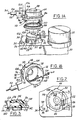
- FIG. 1A a perspective view of housing 20 is shown encasing a portion of a throttle control system.
- the throttle control system is a speed control system which includes servo motor 22 coupled to cable drum 26 via a conventional gearing assembly (not shown) and electromagnetic clutch (not shown) connected to rotating shaft 30 via hub 28.
- Housing 20 is shown including extension 34 having rest stop 38 and protrusion 36 positioned adjacent housing opening 32. Slots 40, 42, and 44 are shown extending outwardly in a radial direction from housing opening 32.
- Cable drum 26 preferably moulded from a plastic material such as nylon
- Cable cover assembly 48 preferably moulded from a plastic material such as nylon, is shown including cable guide 50 connected to Bowden-cable 52 which includes steel cable 54 inserted within sleeve 56. Cable 54 is connected at one end to the engine throttle plate (not shown) and at its opposing end to nipple 60 for insertion into cable drum 26.
- cable cover assembly 48 is structured for manual insertion over cable drum 26 into housing opening 32 and interlocking with housing 20 upon manual rotation.
- Cable cover assembly 48 is now described in greater detail with reference to Figure 1B and continuing reference to Figure 1A.
- Figure 1B is a rotated perspective view of cable cover assembly 48 shown with cable 54 inserted through trough 58. Cable 54 is also shown inserted into storage slot 62 to facilitate transportation and storage before assembly.
- Cable cover assembly 48 includes substantially cylindrical casing 64 having closed end 66 and open end 68. Tabs 70, 72, and 74 are shown integrally formed from cylindrical casing 64 and extending from open end 68 to align with respective slots 40, 42, and 44 of housing 20 during assembly. Cylindrical casing 64 is also shown having recess 78 along open end 68 for alignment with extension 82 of housing 20.
- Collar 86 in this example is integrally formed from cylindrical casing 64 around a portion of its circumferential surface.
- collar 86 and ring seal 88 operate to seal housing opening 20.
- Ring seal 88 is a conventional seal constructed in this example from synthetic rubber.
- Gap 90 is shown formed in collar 86 to form flexible or resilient member 92 along a portion of the outer periphery of collar 86.
- Flap 96 is shown in this example as being integrally formed from resilient member 92 and positioned at its outer end. For reasons described hereinafter, resilient member 92 and flap 96 are shown gradually increasing in width from the junction of resilient member 92 with collar 86. Upwardly extending portion 104 of flap 96 is integrally formed from resilient member 92 for providing a lever to manually compress resilient member 92 by an assembler or repair technician.
- Collar 86 also includes integrally formed upwardly extending portion 106 which acts as a rest stop during compression of resilient member 92.
- Flap 110 is shown integrally formed from collar 86 and spatially separated from flap 96 for accepting protrusion 36 therebetween ( Figures 4 and 5) during the assembly process described below.
- Cable drum 26 is now described in greater detail with reference to Figures 2, 3, and 4 and continuing reference to Figure 1A. More specifically, cable drum 26 is shown as a disk having partial circumferential groove 116 and notch 118 formed through a portion of the circumference.
- Channel 122 extends from notch 118 longitudinally into a portion of cable drum 26 such that channel 122 is open on one longitudinal side ( Figure 3) for accepting lateral insertion of cable 54 as described hereinafter.
- Parallel grooves 124 and 126 are formed through top planar surface 128 of cable drum 26 into channel 122 thereby forming deflectable member 132 between grooves 124 and 126.
- Deflectable member 132 is shown formed with downwardly extending tongue 134 for securing nipple 60 of steel cable 54.
- Cut 138 is formed through top planar surface 128 and groove 116 to prevent pinching of cable 54 during assembly as described hereinafter.
- Bottom drum surface 142 of cable drum 26 includes downward extension 140 for limiting rotation of cable drum 26. More specifically, downward extension 140 abuts against housing extension 82 when cable drum 26 is rotated a predetermined amount as determined by constraints of the throttle control system utilised in a particular application.
- Cable cover assembly 48 is shown locked onto housing 20 with protrusion 36 locked between tabs 96 and 110 in Figures 4 and 5.
- FIG 6 a partial cross-sectional view of cable cover assembly 48 is shown exposing cable drum 26 and rotated into the locked position.
- cable 54 is first laterally inserted through the open longitudinal side of channel 122 and pulled toward cable guide 50.
- Nipple 60 is thereby forced from notch 118 into channel 122 against deflectable member 132. Thereafter, nipple 60 is held in place by tension from deflectable member 132 and tongue 134.
- Cable cover assembly 48 is then inserted into housing 20 such that tabs 70, 72, and 74 of cable cover assembly 48 are inserted through respective slots 40, 42, and 44 of housing 20.
- cable 54 is forced overcut 138 and against groove 116.
- resilient member 92 is in its normal position resting against protrusion 36.
- flap 96 With further rotation of cable cover assembly 48, flap 96 is rotated past protrusion 36 such that resilient member 92 and flap 96 deflect outwardly against rest stop 38, and flap 110 abuts against protrusion 36. As shown in Figure 4 and the corresponding side elevation view in Figure 5, protrusion 36 is then locked between flaps 96 and 110. Accordingly, cable cover assembly 48 is locked in place against housing 20 and restricted from further rotation.
- the assembler pushes against upwardly extending member 104, thereby compressing resilient member 92, and rotates cable cover assembly 48 in a counter-clockwise direction. Flap 96 is then rotated past protrusion 36. Rotation continues until tabs 70, 72, and 74 are aligned with respective housing slots 40, 42, and 44 whereupon cable cover assembly 48 may be removed.
Landscapes
- Engineering & Computer Science (AREA)
- General Engineering & Computer Science (AREA)
- Mechanical Engineering (AREA)
- Health & Medical Sciences (AREA)
- Oral & Maxillofacial Surgery (AREA)
- Chemical & Material Sciences (AREA)
- Combustion & Propulsion (AREA)
- Transportation (AREA)
- Control Of Throttle Valves Provided In The Intake System Or In The Exhaust System (AREA)
- Flexible Shafts (AREA)
Applications Claiming Priority (2)
| Application Number | Priority Date | Filing Date | Title |
|---|---|---|---|
| US288595 | 1988-12-22 | ||
| US07/288,595 US4907553A (en) | 1988-12-22 | 1988-12-22 | Speed control cable attachment |
Publications (3)
| Publication Number | Publication Date |
|---|---|
| EP0375135A2 true EP0375135A2 (de) | 1990-06-27 |
| EP0375135A3 EP0375135A3 (de) | 1992-12-09 |
| EP0375135B1 EP0375135B1 (de) | 1995-09-27 |
Family
ID=23107797
Family Applications (1)
| Application Number | Title | Priority Date | Filing Date |
|---|---|---|---|
| EP89311618A Expired - Lifetime EP0375135B1 (de) | 1988-12-22 | 1989-11-09 | Befestigungsvorrichtung eines Seilzuges |
Country Status (4)
| Country | Link |
|---|---|
| US (1) | US4907553A (de) |
| EP (1) | EP0375135B1 (de) |
| CA (1) | CA1316078C (de) |
| DE (1) | DE68924402T2 (de) |
Cited By (2)
| Publication number | Priority date | Publication date | Assignee | Title |
|---|---|---|---|---|
| EP0536826A1 (de) * | 1991-10-08 | 1993-04-14 | General Motors Corporation | Vorrichtung zum Verbinden eines Seilzuges mit einer Drosselklappe |
| FR2732420A1 (fr) * | 1995-03-27 | 1996-10-04 | Peugeot | Dispositif de montage antivibratoire pour cable, notamment pour cable d'accelerateur de vehicule automobile |
Families Citing this family (12)
| Publication number | Priority date | Publication date | Assignee | Title |
|---|---|---|---|---|
| DE4133858A1 (de) * | 1991-10-12 | 1993-04-15 | Bosch Gmbh Robert | Drosselorganbetaetigungsvorrichtung |
| US6138808A (en) | 1998-02-13 | 2000-10-31 | Dana Corporation | Speed control wrap spring clutch |
| US5979871A (en) * | 1998-03-30 | 1999-11-09 | Ford Motor Company | Clamshell throttle valve assembly |
| US6080075A (en) * | 1999-01-29 | 2000-06-27 | Dana Corporation | Compact actuator for a throttle assembly |
| US6167867B1 (en) * | 1999-04-23 | 2001-01-02 | Delphi Technologies, Inc. | Throttle lever assembly |
| DE19922328A1 (de) * | 1999-05-14 | 2000-11-16 | Sram De Gmbh | Seilführung in einem Schalter für Fahrradgetriebe |
| DE202006003133U1 (de) * | 2006-02-24 | 2007-07-05 | Dolmar Gmbh | Seilzuganlenkung für eine Vergasereinheit |
| US8597280B2 (en) * | 2006-06-13 | 2013-12-03 | Intuitive Surgical Operations, Inc. | Surgical instrument actuator |
| DE102013206132B4 (de) * | 2012-04-11 | 2019-10-31 | GM Global Technology Operations LLC (n. d. Ges. d. Staates Delaware) | Drahtaktuatoren aus aktivem Material mit verstärkten Strukturverbindungselementen |
| DE102016101635B4 (de) * | 2016-01-29 | 2019-02-28 | Rainer Diederich | Seilzugantrieb für eine Drosselklappe eines Fahrzeugs, insbesondere eines ATV bzw. UTV |
| US11220156B2 (en) * | 2017-09-25 | 2022-01-11 | Hanon Systems | Air conditioner for vehicle |
| DE102018119638A1 (de) * | 2018-08-13 | 2020-02-13 | Illinois Tool Works Inc. | Fahrzeuginnenraumkomponente zur Anbringung an einer Fahrzeugkarosserie |
Family Cites Families (14)
| Publication number | Priority date | Publication date | Assignee | Title |
|---|---|---|---|---|
| US3550469A (en) * | 1969-01-21 | 1970-12-29 | Morse Controls Inc | Rotary actuator for push-pull cables |
| US3884449A (en) * | 1973-09-04 | 1975-05-20 | Teleflex Inc | Transmission assembly |
| GB1478983A (en) * | 1973-09-11 | 1977-07-06 | Teleflex Morse Ltd | Motion transmitting systems |
| US4212272A (en) * | 1978-11-09 | 1980-07-15 | General Motors Corporation | Idle speed control device for internal combustion engine |
| DE3101176A1 (de) * | 1981-01-16 | 1982-08-26 | Volkswagenwerk Ag, 3180 Wolfsburg | "lagerung eines bowdenzughebels" |
| US4615234A (en) * | 1981-10-09 | 1986-10-07 | Compagnie Industrielle De Mechanismes En Abrege C.I.M. | Device for winding a traction and thrust cable and a window-raiser provided with such a device |
| GB2119046B (en) * | 1982-04-21 | 1985-07-31 | Hoover Plc | Hose connector for a floor care appliance |
| JPS59215932A (ja) * | 1983-05-23 | 1984-12-05 | Honda Motor Co Ltd | 気化器作動部の作動量調整装置 |
| DE3347070A1 (de) * | 1983-12-24 | 1985-07-04 | Westfälische Metall Industrie KG Hueck & Co, 4780 Lippstadt | Vorrichtung zum regeln der geschwindigkeit eines kraftfahrzeuges |
| US4798258A (en) * | 1984-04-24 | 1989-01-17 | Dana Corporation | Throttle control assembly for a vehicle speed control unit |
| US4703823A (en) * | 1984-09-13 | 1987-11-03 | Nippondenso Co., Ltd. | Vehicle running control system |
| DE3519324A1 (de) * | 1985-05-30 | 1986-12-04 | Robert Bosch Gmbh, 7000 Stuttgart | Stelleinrichtung zur verstellung eines mit einem steuerorgan einer brennkraftmaschine gekoppelten anschlages |
| JPH0658070B2 (ja) * | 1985-07-31 | 1994-08-03 | 株式会社日立製作所 | 絞弁制御装置 |
| JP2518210B2 (ja) * | 1986-06-11 | 1996-07-24 | 株式会社島津製作所 | 液圧駆動システムにおける加速調節装置 |
-
1988
- 1988-12-22 US US07/288,595 patent/US4907553A/en not_active Expired - Fee Related
-
1989
- 1989-09-14 CA CA000611367A patent/CA1316078C/en not_active Expired - Fee Related
- 1989-11-09 DE DE68924402T patent/DE68924402T2/de not_active Expired - Fee Related
- 1989-11-09 EP EP89311618A patent/EP0375135B1/de not_active Expired - Lifetime
Cited By (2)
| Publication number | Priority date | Publication date | Assignee | Title |
|---|---|---|---|---|
| EP0536826A1 (de) * | 1991-10-08 | 1993-04-14 | General Motors Corporation | Vorrichtung zum Verbinden eines Seilzuges mit einer Drosselklappe |
| FR2732420A1 (fr) * | 1995-03-27 | 1996-10-04 | Peugeot | Dispositif de montage antivibratoire pour cable, notamment pour cable d'accelerateur de vehicule automobile |
Also Published As
| Publication number | Publication date |
|---|---|
| EP0375135B1 (de) | 1995-09-27 |
| DE68924402T2 (de) | 1996-03-07 |
| CA1316078C (en) | 1993-04-13 |
| EP0375135A3 (de) | 1992-12-09 |
| DE68924402D1 (de) | 1995-11-02 |
| US4907553A (en) | 1990-03-13 |
Similar Documents
| Publication | Publication Date | Title |
|---|---|---|
| EP0375135B1 (de) | Befestigungsvorrichtung eines Seilzuges | |
| CA2141844C (en) | Rotary temperature control device | |
| DE69700176T2 (de) | Elektromagnetische Kupplung | |
| US5320206A (en) | Coil mounting and terminals for an electromagnetic clutch | |
| CN109098607B (zh) | 线缆滑轮紧固件和紧固车窗升降器用线缆滑轮的方法 | |
| US20080093496A1 (en) | Gear unit for manual or motor-driven cable window lift systems | |
| EP0583212A2 (de) | Mechanismus für die Sicherung einer Riemenscheibe | |
| EP1213471A2 (de) | Formgegossene drehbare Einrastverbindung für Kunstoffluftfilter | |
| EP0651165A1 (de) | Feinbedienungseinrichtung mit Schwingungsdämpfer | |
| KR900000469B1 (ko) | 원격조정되는 균형 조정 시스템 | |
| CA2188219C (en) | Rotating slide-n-snap | |
| US5743756A (en) | Sealed electrical connector with jack screw | |
| US6955335B2 (en) | Throttle device with cover for internal elements | |
| JPH06275360A (ja) | 嵌合操作レバー付きコネクタにおける巻バネの装着方法及び嵌合操作レバー付きコネクタ | |
| US6470768B2 (en) | Accelerator with attachment of pedal arm | |
| JPH05501910A (ja) | 制御ケーブルの長さ自動調節装置 | |
| US3440836A (en) | Flexible cable and casing adaptor tip assembly | |
| US20070175098A1 (en) | Housing for receiving a cable drum | |
| US6093892A (en) | Conduit end fitting with automatic length adjustment | |
| JP2000220344A (ja) | モータユニットハウジング及びパワーウィンドウ用モータユニット | |
| DE69818791T2 (de) | Elektrische Lüftereinheit für Kraftfahrzeugklimaanlage | |
| GB2311666A (en) | Sealed electrical connector with jack screw | |
| EP1155920A2 (de) | Zusammenbau einer Karosserie und eines daran montierten elektrischen Verbinderanschlusskasten | |
| MXPA00003475A (es) | Dispositivo de control remoto por cable para equipo de vehiculo automotor. | |
| US5628471A (en) | Safety belt reeling device with safety belt guide designed for automatic assembly |
Legal Events
| Date | Code | Title | Description |
|---|---|---|---|
| PUAI | Public reference made under article 153(3) epc to a published international application that has entered the european phase |
Free format text: ORIGINAL CODE: 0009012 |
|
| AK | Designated contracting states |
Kind code of ref document: A2 Designated state(s): DE FR GB |
|
| PUAL | Search report despatched |
Free format text: ORIGINAL CODE: 0009013 |
|
| AK | Designated contracting states |
Kind code of ref document: A3 Designated state(s): DE FR GB |
|
| 17P | Request for examination filed |
Effective date: 19930511 |
|
| 17Q | First examination report despatched |
Effective date: 19931228 |
|
| GRAA | (expected) grant |
Free format text: ORIGINAL CODE: 0009210 |
|
| AK | Designated contracting states |
Kind code of ref document: B1 Designated state(s): DE FR GB |
|
| ET | Fr: translation filed | ||
| REF | Corresponds to: |
Ref document number: 68924402 Country of ref document: DE Date of ref document: 19951102 |
|
| PLBE | No opposition filed within time limit |
Free format text: ORIGINAL CODE: 0009261 |
|
| STAA | Information on the status of an ep patent application or granted ep patent |
Free format text: STATUS: NO OPPOSITION FILED WITHIN TIME LIMIT |
|
| 26N | No opposition filed | ||
| REG | Reference to a national code |
Ref country code: FR Ref legal event code: TP Ref country code: FR Ref legal event code: CD |
|
| PGFP | Annual fee paid to national office [announced via postgrant information from national office to epo] |
Ref country code: FR Payment date: 20001121 Year of fee payment: 12 |
|
| REG | Reference to a national code |
Ref country code: GB Ref legal event code: IF02 |
|
| PG25 | Lapsed in a contracting state [announced via postgrant information from national office to epo] |
Ref country code: FR Free format text: LAPSE BECAUSE OF NON-PAYMENT OF DUE FEES Effective date: 20020730 |
|
| REG | Reference to a national code |
Ref country code: FR Ref legal event code: ST |
|
| REG | Reference to a national code |
Ref country code: FR Ref legal event code: ST |
|
| PGFP | Annual fee paid to national office [announced via postgrant information from national office to epo] |
Ref country code: GB Payment date: 20021030 Year of fee payment: 14 |
|
| PGFP | Annual fee paid to national office [announced via postgrant information from national office to epo] |
Ref country code: DE Payment date: 20021111 Year of fee payment: 14 |
|
| PG25 | Lapsed in a contracting state [announced via postgrant information from national office to epo] |
Ref country code: GB Free format text: LAPSE BECAUSE OF NON-PAYMENT OF DUE FEES Effective date: 20031109 |
|
| PG25 | Lapsed in a contracting state [announced via postgrant information from national office to epo] |
Ref country code: DE Free format text: LAPSE BECAUSE OF NON-PAYMENT OF DUE FEES Effective date: 20040602 |
|
| GBPC | Gb: european patent ceased through non-payment of renewal fee |
Effective date: 20031109 |