EP0375420A2 - Zahnradwechselgetriebe für ein Kraftfahrzeug - Google Patents
Zahnradwechselgetriebe für ein Kraftfahrzeug Download PDFInfo
- Publication number
- EP0375420A2 EP0375420A2 EP89313436A EP89313436A EP0375420A2 EP 0375420 A2 EP0375420 A2 EP 0375420A2 EP 89313436 A EP89313436 A EP 89313436A EP 89313436 A EP89313436 A EP 89313436A EP 0375420 A2 EP0375420 A2 EP 0375420A2
- Authority
- EP
- European Patent Office
- Prior art keywords
- gear
- range
- input shaft
- disposed
- shaft
- Prior art date
- Legal status (The legal status is an assumption and is not a legal conclusion. Google has not performed a legal analysis and makes no representation as to the accuracy of the status listed.)
- Granted
Links
- 230000005540 biological transmission Effects 0.000 title claims abstract description 71
- 238000010276 construction Methods 0.000 description 5
- 230000001360 synchronised effect Effects 0.000 description 1
Images



Classifications
-
- F—MECHANICAL ENGINEERING; LIGHTING; HEATING; WEAPONS; BLASTING
- F16—ENGINEERING ELEMENTS AND UNITS; GENERAL MEASURES FOR PRODUCING AND MAINTAINING EFFECTIVE FUNCTIONING OF MACHINES OR INSTALLATIONS; THERMAL INSULATION IN GENERAL
- F16H—GEARING
- F16H3/00—Toothed gearings for conveying rotary motion with variable gear ratio or for reversing rotary motion
- F16H3/02—Toothed gearings for conveying rotary motion with variable gear ratio or for reversing rotary motion without gears having orbital motion
- F16H3/08—Toothed gearings for conveying rotary motion with variable gear ratio or for reversing rotary motion without gears having orbital motion exclusively or essentially with continuously meshing gears, that can be disengaged from their shafts
- F16H3/087—Toothed gearings for conveying rotary motion with variable gear ratio or for reversing rotary motion without gears having orbital motion exclusively or essentially with continuously meshing gears, that can be disengaged from their shafts characterised by the disposition of the gears
- F16H3/091—Toothed gearings for conveying rotary motion with variable gear ratio or for reversing rotary motion without gears having orbital motion exclusively or essentially with continuously meshing gears, that can be disengaged from their shafts characterised by the disposition of the gears including a single countershaft
-
- Y—GENERAL TAGGING OF NEW TECHNOLOGICAL DEVELOPMENTS; GENERAL TAGGING OF CROSS-SECTIONAL TECHNOLOGIES SPANNING OVER SEVERAL SECTIONS OF THE IPC; TECHNICAL SUBJECTS COVERED BY FORMER USPC CROSS-REFERENCE ART COLLECTIONS [XRACs] AND DIGESTS
- Y10—TECHNICAL SUBJECTS COVERED BY FORMER USPC
- Y10T—TECHNICAL SUBJECTS COVERED BY FORMER US CLASSIFICATION
- Y10T74/00—Machine element or mechanism
- Y10T74/19—Gearing
- Y10T74/19219—Interchangeably locked
- Y10T74/19242—Combined gear and clutch
-
- Y—GENERAL TAGGING OF NEW TECHNOLOGICAL DEVELOPMENTS; GENERAL TAGGING OF CROSS-SECTIONAL TECHNOLOGIES SPANNING OVER SEVERAL SECTIONS OF THE IPC; TECHNICAL SUBJECTS COVERED BY FORMER USPC CROSS-REFERENCE ART COLLECTIONS [XRACs] AND DIGESTS
- Y10—TECHNICAL SUBJECTS COVERED BY FORMER USPC
- Y10T—TECHNICAL SUBJECTS COVERED BY FORMER US CLASSIFICATION
- Y10T74/00—Machine element or mechanism
- Y10T74/19—Gearing
- Y10T74/19219—Interchangeably locked
- Y10T74/19377—Slidable keys or clutches
- Y10T74/19386—Multiple clutch shafts
- Y10T74/19391—Progressive
Definitions
- This invention relates to a gear transmission for a vehicle of a synchronous meshing gear type.
- driving gears and driven gears constituting gear trans meshing always with one another are supported on an input shaft connected to a crank shaft of an engine and on an output shaft disposed in parallel with the input shaft.
- a desired speed change range can be obtained by connecting selectively and operatively one of these gear trains to the input shaft.
- a transmission axle for an FF vehicle equipped with such a gear transmission is a gear transmission for a vehicle disclosed in Japanese Utility Model Laid-Open No. 169450/1985 as an application of the present inventor.
- This gear transmission for a vehicle will be explained with reference to Fig. 7 of the accompanying drawings.
- an input shaft 28 disposed in alignment with a crank shaft of an engine is operatively connected to, or is disconnected from, the crank shaft by a clutch 29.
- a first range gear 31, a back range gear 36 and a second range gear 32 are supported fixedly in order named on the input shaft 28 and a third range gear 33 and a fourth range gear 34 are supported rotatably.
- a fifth range gear 35 is fixedly supported at the end of the input shaft 28.
- an output gear 37 is fixedly supported on an output shaft 30, and a gear 38 forming a gear train with the first range gear 31 of the input shaft 28, a gear 39 forming a gear train with the second range gear 32 and a gear 42 forming a gear train with the fifth range gear 35 are rotatably supported on the output shaft 30. Furthermore, a gear 40 forming a gear train with the third range gear 33 and a gear 41 forming a gear train with the fourth range gear 34 are fixedly supported on the output shaft 30.
- a synchronizing device 43 is disposed in order to operatively connect the output shaft 30 to the gear 38 or to the gear 39.
- a sleeve 44 of the synchronizing device 43 is slid and moved towards the gear 38, the rotation of the input shaft 28 is transmitted from the first range gear 31 to the output shaft 30 through the gear 38 and the synchronizing device 43.
- the sleeve 44 of the synchronizing device 43 is slid and moved in the opposite direction, the rotation of the input shaft 28 is transmitted from the second range gear 32 to the output shaft 30 through the gear 39 and the synchronizing device 43.
- the torque transmitted to the output shaft 30 is transmitted further from the output gear 37 to the right and left gears 49, 50 through a differential gear device 60.
- a synchronizing device 45 is disposed between the third range gear 33 and the fourth range gear 34 of the input shaft 28.
- a sleeve 46 of the synchronizing device 45 is slid and moved towards the third range gear 36, the rotation of the input shaft 28 is transmitted from the synchronizing device 45 to the output shaft 30 through the third range gear 33 and the gear 40.
- the sleeve 46 of the synchronizing device 45 is slid and moved in the opposite direction towards the gear 34, the rotation of the input shaft 28 is transmitted from the synchronizing device 45 to the output shaft 30 through the fourth range gear 34 and the gear 41.
- a synchronizing device 47 is disposed at the end of the output shaft 30.
- a sleeve 48 of the synchronizing device 47 is slid and moved towards the gear 42, the rotation of the input shaft 28 is transmitted from the fifth range gear 35 to the output shaft 30 through the gear 42 and the synchronizing device 47.
- the back speed change range of a vehicle is obtained in the following way.
- a gear 51 is fixed integrally with the sleeve 44 of the synchronizing device 43 and this gear 51 and a back idle gear 52 meshing with the back range gear 36 of the input shaft 28 are slidably supported by a shaft 59. Therefore, when the back idle gear 52 is slid and moved and engaged with the gear 51 and with the back range gear 36, the torque of reverse rotation can be obtained at the output gear 37 of the output shaft 30 and a torque transmission system for moving back a vehicle can thus be obtained.
- the differential gear device 60 includes a pinion shaft 55 which is equipped with a pair of pinions 56 and is supported rotatably inside a carrier 54 equipped integrally with a final gear 53 meshing with the output gear 37. Side gears 57 and 58 mesh with these pinions 56 and are formed integrally with axles 49 and 50.
- reference numeral 4 represents a clutch case; 5 is a transmission case; 6 is a cover; 7 is a differential gear case; and 4a, 5a and 6a are case wall members.
- a back range gear R is disposed adjacent to the highest range gear of the input shaft 28 such as a fifth range gear 35
- a gear meshing with the back range gear R is disposed on the output shaft 30
- a synchronizing device is disposed between the back range gear R and the fifth range gear 35.
- the length of the input shaft 28 becomes greater than that in the gear transmission for a vehicle shown in Fig. 7 by the face width of the back range gear R and by the stroke of the sleeve of the synchronizing device. Accordingly, in compact vehicles where the distance (i.e. tread) between the centers of the right and left tire tread surfaces of front wheels is small, the transmission gear axle cannot be mounted.
- a gear transmission for a vehicle which solves the problems with the prior art devices described above, in which a back range gear and an output gear of a second speed change range gear train are disposed on an output shaft adjacent to each other, a gear disposed coaxially with a back idle gear which is disposed on a rotary shaft disposed in parallel with the output shaft and an input gear of the second speed change range gear train disposed on the input shaft are engaged with each other in such a manner as to constitute two gear trains in parallel with each other in the axial direction and to form the first, second and back speed change ranges by the two gear trains; which reduces the size in the axial direction as a whole in comparison with a conventional gear transmission requiring three gear trains in the axial direction; which needs only six gears to obtain the three ranges, that is, the first, second and back ranges, in comparison with the conventional gear transmission requiring seven gears; and which can reduce the number of gears by one and can reduce also the weight and the production cost.
- a gear transmission for a vehicle comprising; an input shaft connected operatively to an engine output shaft through a clutch; an output shaft disposed in parallel with an axial direction of said input shaft; a rotary shart disposed in parallel with the axial direction of said input and output shafts; a plurality of speed change range gear trains consisting of the second range gear train up to the highest range gear train, each being disposed between said input shaft and said output shaft and consisting of a plurality of gears meshing always with one another and having mutually different numbers of teeth; a back idle gear disposed on said rotary shaft and meshing always with said gears disposed on said input shaft; a first range gear disposed on said rotary shaft and meshing always with said second range gear fitted operatively and connectably to said input shaft; first connecting means for operatively connecting said back idle gear and said first range gear; and a back range gear disposed operatively and connectably to said output shaft and meshing always with said back idle gear.
- a gear transmission for a vehicle comprising an input shaft connected operatively to an engine output shaft through a clutch; an output shaft disposed in parallel with an axial direction of said input shaft; a rotary shaft disposed in parallel with the axial direction of said input and output shafts; a plurality of speed change range gear trains consisting of the second range gear train up to the highest range gear train, each being disposed between said input shaft and said output shaft and consisting of a plurality of gears meshing always with one another and having mutually different numbers of teeth; a back idle gear disposed rotatably on said rotary shaft and meshing always with said gears disposed on said input shaft; first connecting means for connecting operatively said rotary shaft and said back idle gear; a first range gear fixed to said rotary shaft and always meshing with said second range gear disposed rotatably on said input shaft; second connecting means for connecting operatively said input shaft and said second range gear; a back range gear fitted rotatably to said output shaft and mesh
- Fig. 1 shows an embodiment of the gear transmission for a vehicle in accordance with the present invention
- Fig. 2 is a side view showing the position relation of gears in the gear transmission for a vehicle shown in Fig. 1.
- This gear transmission for a vehicle includes an input shaft 28 and an output shaft 30 that are stored inside a transmission case and are disposed in parallel with each other in an axial direction, and a rotary shaft 3 which is a third shaft and is disposed in parallel with the input and output shafts 28, 30 in the axial direction.
- the input shaft 28 is disposed in alignment with a crank shaft (not shown) of an engine, for example, and is constructed in such a manner as to be driven and connected to, or is disconnected from, the crank shaft by a clutch 29.
- An output gear 37 is fixedly supported by the output shaft 30. This output gear 37 meshes with a final gear 53 and the final gear 53 is in turn constructed in such a manner as to transmit a torque to a differential gear (not shown), or the like, for example.
- a plurality of speed change range gear trains consisting of second range gears 12, 22 up to the highest range gears 15, 25 meshing always with one another and having mutually different numbers of teeth are disposed between the input shaft 28 and the output shaft 30 of this gear transmission for a vehicle.
- the highest range gear train is a fifth range gear train, and four gear trains, that is, the second range gear train consisting of the second range gears 12, 22, the third range gear train consisting of the third range gears 13, 23, the fourth range gear train consisting of the fourth range gears 14, 24 and the fifth range gear train consisting of the fifth range gears 15, 25, are provided.
- the speed change range gears on the input shaft 28 side that is, the second range gear 12, the third range gear 13, the fourth range gear 14 and the fifth range gear 15, are rotatably fitted to the input shaft 28.
- the speed change range gears on the output shaft 30 side that is, the second range gear 22, the third range gear 23, the fourth range gear 24 and the fifth range gear 25, are fixedly fitted to the output shaft 30.
- a gear 11 is fixedly supported by the input shaft 28 and a back range gear 21 is rotatably fitted to the output shaft 30.
- the first range gear 1 is fixedly fitted to the rotary shaft 3 and a back idle gear 2 is rotatably fitted thereto.
- the back idle gear 2 meshes always with the back range gear 21 and with the gear 11.
- the gear 11, the second range gear 12, the third range gear 13, the fourth range gear 14 and the fifth range gear 15 are disposed sequentially from the clutch 29 side on the input shaft 28.
- the gear 11 is fixedly supported by the input shaft 28 and functions as an input gear of the torque at the time of the first range and the back range.
- the second through fifth range gears 12, 13, 14 and 15 are rotatably supported by the input shaft 28 and function as the input gears of the torque at the time of the second through fifth ranges respectively.
- Each of the gears described above which are rotatably supported by the input shaft 28 can acquire the torque transmission state with the input shaft 28 by a connecting device disposed between the input shaft 28 and each of the gears.
- a synchronizing device 9 for the second stage is disposed as a connecting device for the second range between the input shaft 28 and the second range gear 12.
- a clutch hub in this synchronizing device 9 is spline-fitted to the input shaft 28 and rotates integrally with the latter.
- Torque transmission between the input shaft 28 and the second range gear 12 is accomplished by sliding a sleeve 17 of the synchronizing device 9 and engaging it with a dog gear 62 disposed on the second range gear 12.
- a synchronizing device 19 for the third and fourth ranges is disposed between the third and fourth range gears 13 and 14.
- a clutch hub in this synchronizing device 19 is spline-fitted to the input shaft 28 and rotates integrally with the latter. Torque transmission between.
- the input shaft 28 and the third range gear 13 is accomplished by sliding rightwardly a sleeve 26 of the synchronizing device 19 in the drawing and engaging it with a dog gear 63 disposed on the third range gear 13.
- Torque transmission between the input shaft 28 and the fourth range gear 14 is accomplished by sliding leftwardly the sleeve 26 of the synchronizing device 19 in the drawing and engaging it with a dog gear 64 disposed on the fourth range gear 14.
- a synchronizing device 20 for the fifth range is disposed between the input shaft 28 and the fifth range gear 15.
- a clutch hub in this synchronizing device 20 is spline-fitted to the input shaft 28 and rotates integrally with the latter.
- Torque transmission between the input shaft 28 and the fifth range gear 15 is accomplished by sliding a sleeve 27 of the synchronizing device 20 and engaging it with a dog gear 65 disposed on the fifth range gear 15.
- An output gear 37, the back range gear 21, the second range gear 22, the third range gear 23, the fourth range gear 24 and the fifth range gear 25 are disposed sequentially from the clutch 29 side on the output shaft 30.
- the second, third, fourth and fifth range gears 22, 23, 24 and 25 are fixedly supported by the output shaft 30.
- the second range gear 22 disposed on the output shaft 30 and the second range gear 12 supported by the input shaft 28 always mesh with each other and constitute the second range gear train.
- the third range gear 23 supported by the output shaft 30 and the third range gear 13 supported by the input shaft 28 always mesh with each other and constitute the third range gear train.
- the fourth range gear 24 supported by the output shaft 30 and the fourth range gear 14 supported by the input shaft 28 always mesh with each other and constitute the fourth range gear train.
- the fifth range gear 25 supported by the output shaft 30 and the fifth range gear 15 supported by the input shaft 28 always mesh with each other and constitute the fifth range gear train.
- the back range gear 21 is rotatably supported by the output shaft 30.
- a connecting device 10 for the back range is disposed between the output shaft 30 and the back range gear 21.
- This connecting device 10 can be constituted as the synchronizing device.
- a clutch hub in this connecting device 10 is spline-fitted to the output shaft 30 and rotates integrally with the latter.
- Torque transmission between the output shaft 30 and the back range gear 21 is accomplished by sliding the sleeve 18 of the connecting device 10 and engaging it with a dog gear 66 disposed on the back range gear 21.
- the back range gear 21 always meshes with a back idle gear 2 supported rotatably by the rotary shaft 3.
- the first range gear 1 supported fixedly by the rotary shaft 3 always meshes with the second range gear 12 supported rotatably by the input shaft 28.
- the first range gear 1 can constitute the first range gear train by always meshing with the second range gear 21 of the second range gear train.
- a synchronizing device 8 for the first range as a connecting device for the first range is disposed between the rotary shaft 3 and the back idle gear 2.
- a clutch hub in this synchronizing device 8 is spline-fitted to the rotary shaft 3 and rotates integrally with the latter.
- Torque transmission between the rotary shaft 3 and the back idle gear 2 is accomplished by sliding a sleeve 16 of the synchronizing device 8 and engaging it with a dog gear 61 disposed on the back idle gear 2.
- the gear transmission for a vehicle in accordance with the present invention since the gear transmission for a vehicle in accordance with the present invention has the construction as described above, it operates in the following way.
- the speed change operations to the third, fourth and fifth ranges are the same as those of ordinary gear transmissions in general. Therefore, the explanation on the operation to each of the ranges described above will be omitted.
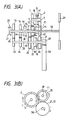
- the torque of the input shaft 28 is transmitted sequentially through the route consisting of the input shaft 28 ⁇ the gear 11 ⁇ the back idle gear 2 ⁇ the synchronizing device 8 ⁇ the rotary shaft 3 ⁇ the first range gear 1 ⁇ the second range gear 12 on the input side ⁇ the second range gear 22 on the output side ⁇ the output shaft 30 ⁇ the output gear 37 ⁇ the final gear 53.
- Their rotating direction is as the one represented by arrow in Fig. 3(B). Therefore, torque transmission of the driving system of the first range can be obtained in this gear transmission for a vehicle.
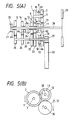
- the torque transmission system of the input shaft 28 becomes the input shaft 28 ⁇ the synchronizing device 9 ⁇ the second range gear 12 on the input side ⁇ the second range gear 22 on the output side ⁇ the output shaft 30 ⁇ the output gear 37 ⁇ the final gear 53.
- Their rotating direction is the one represented by arrow in Fig. 4(B). Therefore, torque transmission of the driving system of the second range can be obtained in this gear transmission for a vehicle.
- Fig. 6 show the operation relation between each gear and the sleeve of the synchronizing device at the time of speed changes to the first, second and back ranges in this gear transmission for a vehicle.
- Table in Fig. 6 summarizes and tabulates the operation relations that have been explained with reference to Figs. 3(A), 3(B), 4(A), 4(B), 5(A) and 5(B).
- the gears with symbol X and the sleeves with symbol X are in the operation state of the torque transmission.
- Reference numerals representing the gears and sleeves are those which are used in the foregoing description.
Landscapes
- Engineering & Computer Science (AREA)
- General Engineering & Computer Science (AREA)
- Mechanical Engineering (AREA)
- Structure Of Transmissions (AREA)
Applications Claiming Priority (2)
| Application Number | Priority Date | Filing Date | Title |
|---|---|---|---|
| JP321968/88 | 1988-12-22 | ||
| JP63321968A JPH0650138B2 (ja) | 1988-12-22 | 1988-12-22 | 車両用歯車変速機 |
Publications (3)
| Publication Number | Publication Date |
|---|---|
| EP0375420A2 true EP0375420A2 (de) | 1990-06-27 |
| EP0375420A3 EP0375420A3 (en) | 1990-08-16 |
| EP0375420B1 EP0375420B1 (de) | 1993-08-11 |
Family
ID=18138442
Family Applications (1)
| Application Number | Title | Priority Date | Filing Date |
|---|---|---|---|
| EP89313436A Expired - Lifetime EP0375420B1 (de) | 1988-12-22 | 1989-12-21 | Zahnradwechselgetriebe für ein Kraftfahrzeug |
Country Status (4)
| Country | Link |
|---|---|
| US (1) | US5085092A (de) |
| EP (1) | EP0375420B1 (de) |
| JP (1) | JPH0650138B2 (de) |
| DE (2) | DE375420T1 (de) |
Cited By (3)
| Publication number | Priority date | Publication date | Assignee | Title |
|---|---|---|---|---|
| EP0595059A1 (de) * | 1992-10-24 | 1994-05-04 | Dr.Ing. h.c. F. Porsche Aktiengesellschaft | Gangschaltgetriebe eines Kraftfahrzeuges |
| EP0629794A1 (de) * | 1993-06-18 | 1994-12-21 | GETRAG Getriebe- und Zahnradfabrik Hermann Hagenmeyer GmbH & Cie | Mehrgang-Stufengetriebe |
| FR2939175A1 (fr) * | 2008-12-03 | 2010-06-04 | Renault Sas | Boite de vitesses a passages sous couple a trois arbres paralleles. |
Families Citing this family (9)
| Publication number | Priority date | Publication date | Assignee | Title |
|---|---|---|---|---|
| DE4116418C1 (de) * | 1991-05-18 | 1992-12-03 | Ford-Werke Ag, 5000 Koeln, De | |
| DE4205668C2 (de) * | 1992-02-25 | 1994-09-29 | Porsche Ag | Gangschaltgetriebe eines Kraftfahrzeugs |
| US5226339A (en) * | 1992-03-25 | 1993-07-13 | Chrysler Corporation | Two-speed transmission for use with electric powered vehicle |
| DE4416930A1 (de) * | 1994-05-13 | 1995-11-16 | Zahnradfabrik Friedrichshafen | Unter Last schaltbares, mehrgängiges Wendegetriebe |
| FR2868141B1 (fr) * | 2004-03-24 | 2007-05-25 | Antonov Automotive Europ | Boite de vitesses pour l'automobile, notamment a double embrayage |
| AU2009352331B2 (en) | 2009-09-14 | 2014-09-11 | Volvo Truck Corporation | Multiple clutch transmission and vehicles and apparatus including a multiple clutch transmission |
| JP2013194751A (ja) * | 2012-03-15 | 2013-09-30 | Yamaha Motor Co Ltd | 変速機及び変速機を備えた車両 |
| CN109505930A (zh) * | 2018-11-16 | 2019-03-22 | 柳工柳州传动件有限公司 | 一种推土机用变速箱 |
| WO2023233429A1 (en) * | 2022-06-02 | 2023-12-07 | Mahindra & Mahindra Limited | A drivetrain for a vehicle |
Family Cites Families (8)
| Publication number | Priority date | Publication date | Assignee | Title |
|---|---|---|---|---|
| ES344980A1 (es) * | 1967-09-12 | 1968-11-16 | Ezpeleta Aizpiri | Sistema perfeccionado para cambio de marchas automatico y semiautomatico para vehiculos. |
| US3744345A (en) * | 1972-04-12 | 1973-07-10 | Kloeckner Humboldt Deutz Ag | Change gear transmission for motor vehicles |
| US3916714A (en) * | 1973-08-27 | 1975-11-04 | Clark Equipment Co | Transmissions |
| US4116082A (en) * | 1976-12-01 | 1978-09-26 | Borg-Warner Corporation | Compact manual transmission for a transversely mounted engine |
| DE3320494A1 (de) * | 1983-06-07 | 1984-12-13 | Getrag Getriebe- Und Zahnradfabrik Gmbh, 7140 Ludwigsburg | Wechselgetriebe mit synchronisiertem rueckwaertsgang |
| US4487967A (en) * | 1983-12-23 | 1984-12-11 | Exxon Research & Engineering Co. | Process for preparing secondary aminoether alcohols |
| JPS60169450U (ja) * | 1984-04-20 | 1985-11-09 | いすゞ自動車株式会社 | 車両用歯車変速機 |
| US4570503A (en) * | 1984-09-17 | 1986-02-18 | Caterpillar Tractor Co. | Countershaft transmission |
-
1988
- 1988-12-22 JP JP63321968A patent/JPH0650138B2/ja not_active Expired - Fee Related
-
1989
- 1989-12-18 US US07/452,089 patent/US5085092A/en not_active Expired - Lifetime
- 1989-12-21 EP EP89313436A patent/EP0375420B1/de not_active Expired - Lifetime
- 1989-12-21 DE DE198989313436T patent/DE375420T1/de active Pending
- 1989-12-21 DE DE89313436T patent/DE68908379T2/de not_active Expired - Fee Related
Cited By (4)
| Publication number | Priority date | Publication date | Assignee | Title |
|---|---|---|---|---|
| EP0595059A1 (de) * | 1992-10-24 | 1994-05-04 | Dr.Ing. h.c. F. Porsche Aktiengesellschaft | Gangschaltgetriebe eines Kraftfahrzeuges |
| EP0629794A1 (de) * | 1993-06-18 | 1994-12-21 | GETRAG Getriebe- und Zahnradfabrik Hermann Hagenmeyer GmbH & Cie | Mehrgang-Stufengetriebe |
| FR2939175A1 (fr) * | 2008-12-03 | 2010-06-04 | Renault Sas | Boite de vitesses a passages sous couple a trois arbres paralleles. |
| EP2194293A1 (de) * | 2008-12-03 | 2010-06-09 | Renault s.a.s. | Unter Drehmoment schaltendes Getriebe mit drei parallelen Wellen |
Also Published As
| Publication number | Publication date |
|---|---|
| JPH02168046A (ja) | 1990-06-28 |
| JPH0650138B2 (ja) | 1994-06-29 |
| DE375420T1 (de) | 1990-11-29 |
| DE68908379D1 (de) | 1993-09-16 |
| US5085092A (en) | 1992-02-04 |
| EP0375420A3 (en) | 1990-08-16 |
| EP0375420B1 (de) | 1993-08-11 |
| DE68908379T2 (de) | 1994-01-13 |
Similar Documents
| Publication | Publication Date | Title |
|---|---|---|
| CA1149196A (en) | Shift mechanism for a five speed transaxle transmission | |
| US4033200A (en) | Five speed overdrive transmission | |
| EP0756107A2 (de) | Getriebe mit Doppelkupplung | |
| US5722291A (en) | Manual transmission with synchronized reverse gear | |
| US4292860A (en) | Transfer device associated with power transmission | |
| US5085092A (en) | Gear transmission for vehicle | |
| GB2412147A (en) | A dual clutch transmission with planetary gearing | |
| US5704247A (en) | Compact manual transaxle for motor vehicles | |
| EP0733825A1 (de) | Wechselgetriebe für Kraftfahrzeuge | |
| MXPA97005530A (es) | Eje de transmision manual compacto para vehiculos motrices | |
| US4738150A (en) | Compact manual transaxle transmission | |
| EP0210394B1 (de) | Kraftübertragung für Kraftfahrzeug | |
| EP0159141A2 (de) | Mehrgängiges Schaltgetriebe | |
| EP1031762A2 (de) | Handschaltgetriebe für Quereinbau | |
| US5697250A (en) | Compact manual transaxle | |
| CN106763553A (zh) | 一种双轴多档位正反转变速装置 | |
| CN117052843B (zh) | 一种四级齿轮变速器、齿轮变速箱及农用车辆 | |
| JP2680708B2 (ja) | 変速歯車装置 | |
| GB2023518A (en) | Motor vehicle transmission apparatus | |
| US4478101A (en) | Mechanical transmission apparatus | |
| KR0162159B1 (ko) | 전진 6단 후진 2단용 트랜스미션 | |
| EP0882908A2 (de) | Mehrgängiges Handschaltgetriebe für Kraftfahrzeuge | |
| CN223563390U (zh) | 用于田园管理机的动力变速变向系统 | |
| CN223825531U (zh) | 用于田园管理机的动力变向系统 | |
| CN218817910U (zh) | 一种梭式换挡收割机变速箱 |
Legal Events
| Date | Code | Title | Description |
|---|---|---|---|
| PUAI | Public reference made under article 153(3) epc to a published international application that has entered the european phase |
Free format text: ORIGINAL CODE: 0009012 |
|
| PUAL | Search report despatched |
Free format text: ORIGINAL CODE: 0009013 |
|
| AK | Designated contracting states |
Kind code of ref document: A2 Designated state(s): DE GB |
|
| AK | Designated contracting states |
Kind code of ref document: A3 Designated state(s): DE GB |
|
| DET | De: translation of patent claims | ||
| 17P | Request for examination filed |
Effective date: 19901127 |
|
| 17Q | First examination report despatched |
Effective date: 19920722 |
|
| GRAA | (expected) grant |
Free format text: ORIGINAL CODE: 0009210 |
|
| AK | Designated contracting states |
Kind code of ref document: B1 Designated state(s): DE GB |
|
| REF | Corresponds to: |
Ref document number: 68908379 Country of ref document: DE Date of ref document: 19930916 |
|
| PLBE | No opposition filed within time limit |
Free format text: ORIGINAL CODE: 0009261 |
|
| STAA | Information on the status of an ep patent application or granted ep patent |
Free format text: STATUS: NO OPPOSITION FILED WITHIN TIME LIMIT |
|
| 26N | No opposition filed | ||
| PGFP | Annual fee paid to national office [announced via postgrant information from national office to epo] |
Ref country code: GB Payment date: 20011119 Year of fee payment: 13 |
|
| PGFP | Annual fee paid to national office [announced via postgrant information from national office to epo] |
Ref country code: DE Payment date: 20011126 Year of fee payment: 13 |
|
| REG | Reference to a national code |
Ref country code: GB Ref legal event code: IF02 |
|
| PG25 | Lapsed in a contracting state [announced via postgrant information from national office to epo] |
Ref country code: GB Free format text: LAPSE BECAUSE OF NON-PAYMENT OF DUE FEES Effective date: 20021221 |
|
| PG25 | Lapsed in a contracting state [announced via postgrant information from national office to epo] |
Ref country code: DE Free format text: LAPSE BECAUSE OF NON-PAYMENT OF DUE FEES Effective date: 20030701 |
|
| GBPC | Gb: european patent ceased through non-payment of renewal fee |
Effective date: 20021221 |