EP0375443A2 - Radialer Luftreifen für Baufahrzeuge - Google Patents
Radialer Luftreifen für Baufahrzeuge Download PDFInfo
- Publication number
- EP0375443A2 EP0375443A2 EP89313471A EP89313471A EP0375443A2 EP 0375443 A2 EP0375443 A2 EP 0375443A2 EP 89313471 A EP89313471 A EP 89313471A EP 89313471 A EP89313471 A EP 89313471A EP 0375443 A2 EP0375443 A2 EP 0375443A2
- Authority
- EP
- European Patent Office
- Prior art keywords
- bead
- layers
- carcass
- sets
- fiber cord
- Prior art date
- Legal status (The legal status is an assumption and is not a legal conclusion. Google has not performed a legal analysis and makes no representation as to the accuracy of the status listed.)
- Withdrawn
Links
Images



Classifications
-
- B—PERFORMING OPERATIONS; TRANSPORTING
- B60—VEHICLES IN GENERAL
- B60C—VEHICLE TYRES; TYRE INFLATION; TYRE CHANGING; CONNECTING VALVES TO INFLATABLE ELASTIC BODIES IN GENERAL; DEVICES OR ARRANGEMENTS RELATED TO TYRES
- B60C15/00—Tyre beads, e.g. ply turn-up or overlap
- B60C15/0009—Tyre beads, e.g. ply turn-up or overlap features of the carcass terminal portion
- B60C15/0036—Tyre beads, e.g. ply turn-up or overlap features of the carcass terminal portion with high ply turn-up, i.e. folded around the bead core and terminating radially above the point of maximum section width
-
- B—PERFORMING OPERATIONS; TRANSPORTING
- B60—VEHICLES IN GENERAL
- B60C—VEHICLE TYRES; TYRE INFLATION; TYRE CHANGING; CONNECTING VALVES TO INFLATABLE ELASTIC BODIES IN GENERAL; DEVICES OR ARRANGEMENTS RELATED TO TYRES
- B60C15/00—Tyre beads, e.g. ply turn-up or overlap
- B60C15/06—Flipper strips, fillers, or chafing strips and reinforcing layers for the construction of the bead
-
- Y—GENERAL TAGGING OF NEW TECHNOLOGICAL DEVELOPMENTS; GENERAL TAGGING OF CROSS-SECTIONAL TECHNOLOGIES SPANNING OVER SEVERAL SECTIONS OF THE IPC; TECHNICAL SUBJECTS COVERED BY FORMER USPC CROSS-REFERENCE ART COLLECTIONS [XRACs] AND DIGESTS
- Y10—TECHNICAL SUBJECTS COVERED BY FORMER USPC
- Y10T—TECHNICAL SUBJECTS COVERED BY FORMER US CLASSIFICATION
- Y10T152/00—Resilient tires and wheels
- Y10T152/10—Tires, resilient
- Y10T152/10495—Pneumatic tire or inner tube
- Y10T152/10819—Characterized by the structure of the bead portion of the tire
- Y10T152/10828—Chafer or sealing strips
-
- Y—GENERAL TAGGING OF NEW TECHNOLOGICAL DEVELOPMENTS; GENERAL TAGGING OF CROSS-SECTIONAL TECHNOLOGIES SPANNING OVER SEVERAL SECTIONS OF THE IPC; TECHNICAL SUBJECTS COVERED BY FORMER USPC CROSS-REFERENCE ART COLLECTIONS [XRACs] AND DIGESTS
- Y10—TECHNICAL SUBJECTS COVERED BY FORMER USPC
- Y10T—TECHNICAL SUBJECTS COVERED BY FORMER US CLASSIFICATION
- Y10T152/00—Resilient tires and wheels
- Y10T152/10—Tires, resilient
- Y10T152/10495—Pneumatic tire or inner tube
- Y10T152/10819—Characterized by the structure of the bead portion of the tire
- Y10T152/10837—Bead characterized by the radial extent of apex, flipper or chafer into tire sidewall
-
- Y—GENERAL TAGGING OF NEW TECHNOLOGICAL DEVELOPMENTS; GENERAL TAGGING OF CROSS-SECTIONAL TECHNOLOGIES SPANNING OVER SEVERAL SECTIONS OF THE IPC; TECHNICAL SUBJECTS COVERED BY FORMER USPC CROSS-REFERENCE ART COLLECTIONS [XRACs] AND DIGESTS
- Y10—TECHNICAL SUBJECTS COVERED BY FORMER USPC
- Y10T—TECHNICAL SUBJECTS COVERED BY FORMER US CLASSIFICATION
- Y10T152/00—Resilient tires and wheels
- Y10T152/10—Tires, resilient
- Y10T152/10495—Pneumatic tire or inner tube
- Y10T152/10855—Characterized by the carcass, carcass material, or physical arrangement of the carcass materials
- Y10T152/10864—Sidewall stiffening or reinforcing means other than main carcass plies or foldups thereof about beads
Definitions
- the tires for trucks and buses are used for running at speeds of the order of from several tens Km/h to one hundred and several tens km/h mainly on paved flat roads. In other words, they are used for so to say high speed running. Therefore, sizes of these tires are 10.00-20 to 11.00-20 in Japan and at the maximum 12.00-20 even in the Western countries although there are some exceptions.
- the tires for construction vehicles and the like are used on rough grounds which are not prepared as roads. In addition to dispersion of fragments or broken pieces of stones and rocks on these grounds, they have large irregularities on their surfaces, so that the tires for construction vehicles are obliged to be used at low speeds. Sizes of these tires range from 18.00-25 to as much as 36.00-51 or 40.00-57. In comparison with such large tires, the tires for trucks and buses may be rather called as small type.
- treads of the tires are subjected to repeated forces at high frequencies so that wear-resistance is generally the most important.
- the tires for construction vehicles they have thick rubbers of treads resulting from the large sizes so that repeated forces acting upon the treads will promote heat generation and heat storage cycles.
- the tread rubbers are subjected to repeated strain inputs to generate high temperature heat and to store the heat due to poor heat transfer of the rubbers. Therefore, there is a risk of high temperature rupture of the rubbers due to heat storage with high possibility.
- allowable continuous maximum speeds of the tires for trucks and buses are 100 km/h according to a standard, those values of tires for construction vehicles are considerably low.
- allowable maximum speeds of tires for dump trucks are 50 km/h according to JIS (referring now to JATMA YEAR BOOK 1988 in substituting therefor) or 64 km/h (40 MPH) according to TRA.
- maximum loads of the tires for construction vehicles are larger than those of tires for trucks and buses.
- maximum loads for both tires of 12.00-24 are as follows at inner pressure of 5 kgf/cm2.
- Tires for trucks and buses 2,865 kgf (dual wheels) 3,005 kgf
- Tires for construction vehicles 3,460 kgf
- the maximum load supporting rate of the tires for the construction vehicles is 1.21-1.15 times higher at the same inner pressure than that of the tires for trucks and buses.
- the separation failure of the item (1) can be basically solved by utilizing radially arranged carcasses of steel cord plies which are theoretically of less heat generation and easy heat dispersion.
- the failure of the item (2) can be basically solved by using thick treads which are also accepted in the standards in addition to utilizing a carcass having a radially arranged steel cord ply.
- the failure of the item (3) cannot be basically solved by the above carcasses and there is no solution in standards.
- radial tires are essential for solving the problems of the items (1) and (2) although their bead portions are weak points in comparison with bias tires using nylon cords, it is urgently required to prevent failures at bead portions.
- Such an improvement of radial tire for preventing failures at bead portions is the most important for applying radial tires to construction vehicles as an industrial utilization. The reason will be clarified by the following explanation.
- the exchanging tires are usually intentionally effected in a complete maintenance factory having together with adjustment and repairing of other portions of the vehicle at a time of tire exchanging which was previously presumed from wear of the tires.
- the bead portions located immediately radially outwardly of the rim flange fall down axially outwardly by the bending moments B.M. Therefore, shearing strains are caused by the axial compressive forces A.C. and the bending moment B.M. between turn-up portions of carcass plies and rubbers and between bead portion reinforcing layers embedded in the bead portions and rubbers thereabout under falling down of the bead portions by the bending moment B.M. Moreover, the shearing strains are added with shearing strains in proportion to amount of the falling down.
- the failure of the bead portion is caused by these shearing strains in the following manner. Cracks occur at ends of cords outside the bead portions among reinforcing cords and progress along directions of the cords. Fragments of rubber and gases accumulate in the cracks to cause the portions including the cracks to swell until the accumulated substances get away therefrom and cords therein are broken to cause failures of the bead portions.
- steel cord reinforcing layers have been arranged along turn-up portions of the carcass plies and organic fiber layers such as nylon layers have been arranged outwardly of the steel cord reinforcing layers for the purpose of equalizing difference in rigidity caused by the steel cord reinforcing layers.
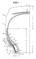
- Fig. 1 illustrates one embodiment of a radial tire for a construction vehicle according to the invention.
- the tire comprises a cylindrical tread 1 and sidewalls 2 which extend from both ends of the tread 1 and terminate in bead portions 4 having bead cores 3 embedded in inner edges of the sidewalls 2.
- Fig. 1 illustrates the left half of the tire. It is of course understood that a right half of the tire is similar in construction to the left half shown so that the tire is in symmetry.
- a carcass including a steel cord ply turned up around the bead core 3 of course extends to the other bead core not shown in the right half of the tire and is turned up around the other bead core in the same manner.
- a plurality of strip layers as a belt 6, including substantially inextensible cords, for example, steel cords.
- the belt 6 and the carcass 5 form a main reinforcing layer for the tire.
- bead reinforcing layers 7 each extending radially outwardly from the proximity of the bead core 3 along the ply turn-up portion 5′ of the carcass 5.
- the bead reinforcing layer 7 for each bead core 3 includes fiber cord layer sets, each set consisting of at least two layers. At least two sets of the fiber cord layers (three sets R1, R2 and R3 in the embodiment shown in Fig. 1) are embedded in the bead portion 4 and extend radially outwardly from the proximity of the axially outwardly of the bead core 3 with the respective sets of the fiber cord layers spaced by minimum distances d1 and d2 in the proximity of the bead core 3 and maximum distances D1 and D2 at the outer ends radially outwardly of the bead core.
- Fig. 1 illustrates a bead filler ruber 8, partition rubbers 9a and 9b of the bead portion reinforcing layers 7, and a side protector 10 formed extending from a buttress of the sidewall 2.
- a rim 11 for mounting the tire thereon has a rim flange 12. The rim 11 is usually according to the JIS or TRA except particular cases.
- H is a maximum distance from a bead base line l to an outermost position of the tread 1 and h is a distance from the bead base line l to a radially outermost end of the ply turn-up portion 5′.
- the bead base line l is a straight line passing through a point spaced from a tire axis by a distance one half of a nominal diameter of the rim and in parallel with the tire axis. It is usual that the h is substantially (0.4-0.6) H.
- RH1 (2.4-1.6) FH, more preferably (2.2-1.8) FH
- RH2 (2.1-1.3) FH, more preferably (1.9-1.5) FH
- RH3 (1.8-1.1) FH, more preferably (1.6-1.2) FH
- RH4 (1.9-1.1) FH, more preferably (1.7-1.3) FH
- d (0.17-0.09) FH, more preferably (0.15-0.11) FH
- the direction of the cord may be arranged with in a range of 90°-20° which is an angle made by the cord and a tangent to a phantom circle at a point of intersection of the cord and the phantom circle having a center at a tire rotating center and a radius which is one half of a nominal diameter of the rim 11 plus the flange height FH.
- the directions of the cords may be R1: 90°-60°, R2: 60°-30° and R3: 50°-20° for the respective cords or all these directions of the cords may be the substantially the same angle within 20°-40°.
- partition rubbers 9a and 9b shown in Fig. 1 it is preferable to use, for example, a rubber having a physical property of a modulus 10-30 kgf/cm2 upon 100% elongation.
- the carcass 5 comprises steel cord plies.
- cords of the carcass 5 are of a strand construction and one layer of 1 ⁇ 3 + 9 + 15 + 1 is arranged in a radial surface of the tire.
- two steel cord layers of 7 ⁇ 7 + 1 and two steel cord layers of 3 ⁇ 7 of strand construction are preferably arranged in cord angles of 20°-40° so as to form cord angles across an equatorial plane of the tire.
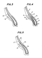
- the bead reinforcing layers 7 have been explained referring to Figs. 1 and 2 using three sets of the fiber cord layers of which two layers form one set. Two set of fiber cord layers may be employed as shown in Fig. 3. As shown in Fig. 4, moreover, the bead reinforcing layers 7 may be four sets which include additional fiber cord layers R4 forming one set consisting of two layers which divide the bead filler rubber 8 into two parts inside the ply turn-up portion 5′ and extend along a boundary between bead filler rubbers A and B made of hard and soft rubbers, respectively.
- the bead reinforcing layers 7 may be arranged in a modified manner as shown in Fig. 5, wherein a ply turn-up portion 5′ is embraced by fiber cord layers R′1 and R′4 and a spaced arranged maximum distance d includes a diameter of cords of the ply turn-up portion 5′.
- the fiber cord layers R′4 may lu extend along the inside of the ply turn-up portion 5′ and further fiber cord layers R5 may be added along the inside of the carcass 5.
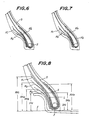
- fiber cord layers R ⁇ 4 so-called flippers may surround the bead filler 8 and be turned up around the '6 bead core 3 together with the carcass 5.
- the fiber cord layers R′4 in Fig. 6 may be divided into layers R ⁇ 4 and R′5 to embrace the bead filler ruber 8 as shown in Fig. 7.
- a steel cord reinforcing layer S may be added to the construction shown in Fig. 1 or 2.
- the steel cord reinforcing layer S may be arranged along the carcass layer 5 surrounding the bead core 3 and inside the bead reinforcing layer 7 made of the fiber cord layers R1, R2 and R3.
- radial maximum distances of the steel cord reinforcing layer S from the bead base line are SH1: (0.6-1.2) FH, preferably (0.7-1.0) FH on an axially outer side of the bead core 3 and SH2: (0.8-1.4) FH, preferably (0.9-1.2) FH on an axially inner side of the bead core 3.
- a radial maximum distance RH4 of the fiber cord layer R1 from the bead base line on the inner side of the bead core 3 is much longer than the maximum distance SH2.
- any separations at ends of the steel cords S are restrained so to accomplish more effective reinforcement.
- the bead reinforcing layers 7 in the above embodiments have been explained as they include sets of layers made of two layers.
- each set is made of three fiber cord layers and two sets of layers R1 and R2 are provided according to the embodiment in Fig. 3.
- Fig. 10 illustrates a section of a radial tire for a construction vehicle of the prior art, whose bead reinforcing means are shown in various modifications in Figs. 11-13.
- a steel cord reinforcing layer M arranged in a zone where a carcass 5 is turned up around a bead core 3, and usually two fiber cord reinforcing layer F arranged covering an end of the steel cord reinforcing layer M on a side of a turn-up portion 5′ so as to serve to reinforce the bead portion.
- the fiber cord reinforcing layer F serves to prevent separations between an end of the steel cord reinforcing layer M and rubber in the proximity of the end of the layer M.
- the number of the fiber cord reinforcing layers F is increased to the order of six to increase the bead reinforcing effect.
- excessive interlaminar shearing strains occur in a radially outer zone of the fiber cord reinforcing layers F to cause separations between the reinforcing layers resulting in breakage of the cords.
- respective sets of fiber reinforcing layers are formed by at least two layers and these sets of reinforcing layers are arranged spaced at more than two positions to reduce strains to be supported by the reinforcing layers. More particularly, thick rubbers are inserted between the proximities or ends of the reinforcing layers where falling down of the layes are maximum, thereby restraining the falling down of the bead portions and at the same time reducing the strains as a whole to obtain a double effect.
- Tires having a size of 18.00 R33 for off the road were prepared with the fundamental construction in Fig. 1 and the reinforcements according to Fig. 2 (Embodiment 1) and Fig. 3 (Embodiment 2).
- tires of the same size of the prior art were prepared having the bead reinforcement as shown in Fig. 12 and tires of the same size (Comparative Example) were prepared which having no bead reinforcement in order to eliminate the source of failures at the bead portions.
- the fiber cord layers had nylon cords of 1260 d/2 whose cord angles were 30°, each angle formed by a tangent to a phantom circle at an intersection of a cord and the phantom circle concentric to a rim flange 12 and having a diameter equal to that of the rim flange 12.
- Directions of the fiber cords in one set were alternately intersected and a mean density of the cords was 32.6/5 cm.
- partition rubbers 9a and 9b having a modulus of 22 kg/cm2 on 100% elongation so that distances d between the respective sets of cord layers were 0.13 FH (8 mm).
- Respective values of RH were in Embodiment 1 RH1 : 2.0 FH (127 mm) RH2 : 1.7 FH (108 mm) RH3 : 1.4 FH ( 89 mm) RH4 : 1.5 FH ( 95 mm) and in Embodiment 2 RH1 : 2.0 FH (127 mm) RH2 : 1.7 FH (108 mm) and RH4 : 1.5 FH ( 95 mm).
- a spaced arranged maximum distance d was 1.0 mm-2.0 mm and a step was about 15 mm which was a difference in length between longer and shorter fiber cord layers at the radially outer end thereof.
- a carcass 3 of each of all the tires was one ply of steel cords radially arranged and having a strand construction of 1 ⁇ 3 + 9 + 15 + 1.
- a belt 6 of each of all the tire included steel cord layers comprising two layers of 7 ⁇ 7 + 1 and two layers of 3 ⁇ 7, and these cords intersected with each other whose angles were 23° with respect to an equatorial plane.
- the tires were filled with inner pressure of 7.0 kgf/cm2 and tested on their drum bead durability on a drum having a diameter of 5 m of a bead durability testing machine. Each of the tires was rolled on the drum at a circumferential speed of 20 km/h under a load of 15.9 tons (150% load). Comparison of durability in connection with lateral rigidity in axial directions was obtained as follows. Comparative Example Prior art Embodiment 1 Embodiment 2 Longitudinal rigidity 100 103 105.5 103.2 Bead durability 100 170 310 228 These results are shown in Fig. 14. In the results, larger numerals are better.
Landscapes
- Engineering & Computer Science (AREA)
- Mechanical Engineering (AREA)
- Tires In General (AREA)
Applications Claiming Priority (2)
| Application Number | Priority Date | Filing Date | Title |
|---|---|---|---|
| JP63322153A JPH02169309A (ja) | 1988-12-22 | 1988-12-22 | 建設車両用ラジアルタイヤ |
| JP322153/88 | 1988-12-22 |
Publications (2)
| Publication Number | Publication Date |
|---|---|
| EP0375443A2 true EP0375443A2 (de) | 1990-06-27 |
| EP0375443A3 EP0375443A3 (de) | 1991-03-13 |
Family
ID=18140528
Family Applications (1)
| Application Number | Title | Priority Date | Filing Date |
|---|---|---|---|
| EP19890313471 Withdrawn EP0375443A3 (de) | 1988-12-22 | 1989-12-21 | Radialer Luftreifen für Baufahrzeuge |
Country Status (4)
| Country | Link |
|---|---|
| US (1) | US5048584A (de) |
| EP (1) | EP0375443A3 (de) |
| JP (1) | JPH02169309A (de) |
| AU (1) | AU611832B2 (de) |
Cited By (7)
| Publication number | Priority date | Publication date | Assignee | Title |
|---|---|---|---|---|
| EP0565944A1 (de) * | 1992-04-06 | 1993-10-20 | The Goodyear Tire & Rubber Company | Radialer Luftreifen mit zwei nichtmetallischen Wulstverstärkungsschichten |
| TR26293A (tr) * | 1992-07-13 | 1995-03-15 | Libeltex Nv | Yolcu tasimaciliginda kullanilan koltuklarda uygulanan dösemelere destek olarak kullanilan dokunmamis materyal. |
| EP0997325A1 (de) * | 1998-10-29 | 2000-05-03 | Sumitomo Rubber Industries Ltd. | Reifen |
| WO2007003246A1 (de) | 2005-07-01 | 2007-01-11 | Continental Aktiengesellschaft | Fahrzeugluftreifen mit verstärkter wulstkonstruktion |
| WO2008074337A1 (en) * | 2006-12-18 | 2008-06-26 | Pirelli Tyre S.P.A. | Tire having an improved bead structure |
| EP2130689A3 (de) * | 2008-06-04 | 2010-08-25 | The Yokohama Rubber Co., Ltd. | Luftreifen |
| EP3501857A1 (de) * | 2017-12-15 | 2019-06-26 | The Goodyear Tire & Rubber Company | Luftreifen mit einer robusten wulstflächenstruktur |
Families Citing this family (18)
| Publication number | Priority date | Publication date | Assignee | Title |
|---|---|---|---|---|
| US5431209A (en) * | 1991-06-26 | 1995-07-11 | Sumitomo Rubber Industries, Ltd. | Passenger tire with low bead apex volume |
| JP2870703B2 (ja) * | 1990-11-28 | 1999-03-17 | 住友ゴム工業 株式会社 | 空気入りタイヤ |
| US5323829A (en) * | 1992-12-28 | 1994-06-28 | The Goodyear Tire & Rubber Company | Tire with carbon fiber reinforcement |
| US5569341A (en) * | 1993-12-21 | 1996-10-29 | Bridgestone Corporation | Pneumatic radial tire with side cut resistance |
| US5526863A (en) * | 1994-04-18 | 1996-06-18 | Michelin Recherche Et Technique S.A. | Tire with reduced bead mass |
| ES2181997T3 (es) * | 1996-07-08 | 2003-03-01 | Bridgestone Corp | Cubiertas neumaticas radiales robustas. |
| US6138733A (en) * | 1997-03-25 | 2000-10-31 | Bridgestone Corporation | Pneumatic radial tire with a two part chafer |
| JP4707842B2 (ja) * | 2001-01-24 | 2011-06-22 | 株式会社ブリヂストン | 重荷重用空気入りラジアルタイヤ |
| US7188655B2 (en) * | 2001-07-10 | 2007-03-13 | Bridgestone Corporation | Pneumatic tire |
| DE102004059772B4 (de) * | 2004-12-11 | 2020-11-19 | Martin Kraus | Fahrzeugluftreifen |
| JP4746314B2 (ja) * | 2004-12-20 | 2011-08-10 | 株式会社ブリヂストン | 重荷重用空気入りラジアルタイヤ |
| US7320350B2 (en) * | 2005-07-08 | 2008-01-22 | Bridgestone Firestone North American Tire, Llc | Sidewall reinforcing layer for pneumatic tires |
| JP4741955B2 (ja) * | 2006-02-13 | 2011-08-10 | 株式会社ブリヂストン | 空気入りタイヤ |
| JP5287144B2 (ja) * | 2008-10-28 | 2013-09-11 | 横浜ゴム株式会社 | 空気入りタイヤ |
| JP5633217B2 (ja) * | 2010-07-09 | 2014-12-03 | 横浜ゴム株式会社 | 空気入りラジアルタイヤ |
| JP5682210B2 (ja) * | 2010-10-05 | 2015-03-11 | 横浜ゴム株式会社 | 空気入りタイヤ |
| KR101385409B1 (ko) * | 2012-08-02 | 2014-04-14 | 한국타이어 주식회사 | 비드 내구성을 강화한 중하중용 타이어 |
| CA3146469A1 (en) * | 2019-08-08 | 2021-02-11 | Filippo GALLI | Bicycles tyre |
Family Cites Families (16)
| Publication number | Priority date | Publication date | Assignee | Title |
|---|---|---|---|---|
| GB1276298A (en) * | 1968-07-23 | 1972-06-01 | Dunlop Holdings Ltd | Improvements in or relating to pneumatic tyres |
| FR1600345A (de) * | 1968-12-31 | 1970-07-20 | ||
| FR2109394A5 (de) * | 1970-10-14 | 1972-05-26 | Michelin & Cie | |
| NL7201568A (de) * | 1971-03-17 | 1972-09-19 | ||
| IT1045356B (it) * | 1973-06-12 | 1980-05-10 | Pirelli | Perfezionamento ai pneumatici radiali provvisti di struttura di irrigidimento circonferenziale dei fianchi |
| IT995522B (it) * | 1973-09-28 | 1975-11-20 | Pirelli | Perfezionamenti ai talloni di pneumatici a carcassa radiale |
| JPS6050601B2 (ja) * | 1975-05-27 | 1985-11-09 | 横浜ゴム株式会社 | 空気入りタイヤ |
| IT1066965B (it) * | 1976-07-02 | 1985-03-12 | Pirelli | Perfezionamento ai talloni di pneumatici a carcassa radiale |
| JPS53121304A (en) * | 1977-03-31 | 1978-10-23 | Bridgestone Corp | Arrangement for strengthening head section of heavy-duty pneumatic radial type |
| JPS5540447A (en) * | 1978-09-14 | 1980-03-21 | Olympus Optical Co Ltd | Image correcting method in zoom lens |
| JPS5690707A (en) * | 1979-12-24 | 1981-07-23 | Bridgestone Corp | Air-filled radial tire for heavy vehicle |
| US4716950A (en) * | 1984-09-29 | 1988-01-05 | The Yokohama Rubber Co., Ltd. | Radial tire for passenger car |
| AU561964B2 (en) * | 1984-11-16 | 1987-05-21 | Bridgestone Corporation | Bead chafer construction |
| JP2530807B2 (ja) * | 1985-06-13 | 1996-09-04 | 住友ゴム工業 株式会社 | 重荷重用ラジアルタイヤのビ−ド部補強構造 |
| US4688616A (en) * | 1985-09-11 | 1987-08-25 | Sumitomo Rubber Industries Ltd. | Pneumatic radial tires for heavy vehicles |
| FR2615453B1 (fr) * | 1987-05-21 | 1990-07-20 | Bridgestone Corp | Pneumatique a carcasse radiale a talons renforces |
-
1988
- 1988-12-22 JP JP63322153A patent/JPH02169309A/ja active Pending
-
1989
- 1989-12-18 AU AU46942/89A patent/AU611832B2/en not_active Ceased
- 1989-12-19 US US07/452,934 patent/US5048584A/en not_active Expired - Fee Related
- 1989-12-21 EP EP19890313471 patent/EP0375443A3/de not_active Withdrawn
Cited By (11)
| Publication number | Priority date | Publication date | Assignee | Title |
|---|---|---|---|---|
| EP0565944A1 (de) * | 1992-04-06 | 1993-10-20 | The Goodyear Tire & Rubber Company | Radialer Luftreifen mit zwei nichtmetallischen Wulstverstärkungsschichten |
| TR27270A (tr) * | 1992-04-06 | 1994-12-22 | Goodyear Tire & Rubber | Metalik olmayan iki cepere sahip pnömatik radyal lastik. |
| TR26293A (tr) * | 1992-07-13 | 1995-03-15 | Libeltex Nv | Yolcu tasimaciliginda kullanilan koltuklarda uygulanan dösemelere destek olarak kullanilan dokunmamis materyal. |
| EP0997325A1 (de) * | 1998-10-29 | 2000-05-03 | Sumitomo Rubber Industries Ltd. | Reifen |
| US6427743B1 (en) | 1998-10-29 | 2002-08-06 | Sumitomo Rubber Industries, Ltd. | Pneumatic tire |
| US6962183B2 (en) | 1998-10-29 | 2005-11-08 | Sumitomo Rubber Industries, Ltd. | Pneumatic tire |
| WO2007003246A1 (de) | 2005-07-01 | 2007-01-11 | Continental Aktiengesellschaft | Fahrzeugluftreifen mit verstärkter wulstkonstruktion |
| WO2008074337A1 (en) * | 2006-12-18 | 2008-06-26 | Pirelli Tyre S.P.A. | Tire having an improved bead structure |
| CN101610919B (zh) * | 2006-12-18 | 2012-03-28 | 倍耐力轮胎股份公司 | 具有改进的胎圈结构的轮胎 |
| EP2130689A3 (de) * | 2008-06-04 | 2010-08-25 | The Yokohama Rubber Co., Ltd. | Luftreifen |
| EP3501857A1 (de) * | 2017-12-15 | 2019-06-26 | The Goodyear Tire & Rubber Company | Luftreifen mit einer robusten wulstflächenstruktur |
Also Published As
| Publication number | Publication date |
|---|---|
| US5048584A (en) | 1991-09-17 |
| JPH02169309A (ja) | 1990-06-29 |
| AU4694289A (en) | 1990-07-12 |
| EP0375443A3 (de) | 1991-03-13 |
| AU611832B2 (en) | 1991-06-20 |
Similar Documents
| Publication | Publication Date | Title |
|---|---|---|
| US5048584A (en) | Radial tire for constuction vehicle | |
| US5482102A (en) | Pneumatic motorcycle tire for improved cornering and straight running stability | |
| EP0847337B1 (de) | Lkw-reifen mit niedrigem höhen-/breitenverhältnis | |
| EP1356956B1 (de) | Gürtelpaket für LKW "super single" Reifen | |
| EP0318128A2 (de) | Radialer Luftreifen für LKW | |
| EP0604820B1 (de) | Verbesserter Erdwebegungsfarhzeugreifen | |
| US5379819A (en) | Pneumatic tire with reinforced bead portions | |
| US5082042A (en) | Belt arrangement for high durable pneumatic radial tire | |
| EP0622253B1 (de) | Radiale Luftreifen | |
| US6058997A (en) | Pneumatic radial tire having at least two zigzag belt layers | |
| US4454903A (en) | Multi-ply belt pneumatic tire | |
| JP3419830B2 (ja) | 空気入りラジアルタイヤ | |
| EP2231423B1 (de) | Nutzfahrzeug-reifen mit verbesserter gürtelstruktur | |
| EP2261060B1 (de) | Motorradreifen | |
| EP2173573B1 (de) | Fahrzeugreifen für schwerlasten | |
| CA1315653C (en) | Pneumatic radial tire | |
| EP0508813B1 (de) | Geländeluftreifen | |
| EP0161202B1 (de) | Luftreifen | |
| JP3597610B2 (ja) | 重荷重用空気入りタイヤ | |
| JPS592908A (ja) | 空気入りタイヤ | |
| US6138733A (en) | Pneumatic radial tire with a two part chafer | |
| EP0779163B1 (de) | Motorradluftreifen | |
| EP0327955A2 (de) | Radialer Luftreifen | |
| JP3848787B2 (ja) | 建設車両用空気入りバイアスタイヤ | |
| JPH09207510A (ja) | 空気入りラジアルタイヤ |
Legal Events
| Date | Code | Title | Description |
|---|---|---|---|
| PUAI | Public reference made under article 153(3) epc to a published international application that has entered the european phase |
Free format text: ORIGINAL CODE: 0009012 |
|
| AK | Designated contracting states |
Kind code of ref document: A2 Designated state(s): ES FR LU |
|
| PUAL | Search report despatched |
Free format text: ORIGINAL CODE: 0009013 |
|
| AK | Designated contracting states |
Kind code of ref document: A3 Designated state(s): ES FR LU |
|
| 17P | Request for examination filed |
Effective date: 19910327 |
|
| 17Q | First examination report despatched |
Effective date: 19920720 |
|
| STAA | Information on the status of an ep patent application or granted ep patent |
Free format text: STATUS: THE APPLICATION IS DEEMED TO BE WITHDRAWN |
|
| 18D | Application deemed to be withdrawn |
Effective date: 19930202 |