EP0375630A2 - Vorrichtung zur Reparatur von beschädigten Fahrzeugkarosserien - Google Patents
Vorrichtung zur Reparatur von beschädigten Fahrzeugkarosserien Download PDFInfo
- Publication number
- EP0375630A2 EP0375630A2 EP89830532A EP89830532A EP0375630A2 EP 0375630 A2 EP0375630 A2 EP 0375630A2 EP 89830532 A EP89830532 A EP 89830532A EP 89830532 A EP89830532 A EP 89830532A EP 0375630 A2 EP0375630 A2 EP 0375630A2
- Authority
- EP
- European Patent Office
- Prior art keywords
- base
- linear actuator
- junction point
- accidented
- pair
- Prior art date
- Legal status (The legal status is an assumption and is not a legal conclusion. Google has not performed a legal analysis and makes no representation as to the accuracy of the status listed.)
- Withdrawn
Links
Images


Classifications
-
- B—PERFORMING OPERATIONS; TRANSPORTING
- B21—MECHANICAL METAL-WORKING WITHOUT ESSENTIALLY REMOVING MATERIAL; PUNCHING METAL
- B21D—WORKING OR PROCESSING OF SHEET METAL OR METAL TUBES, RODS OR PROFILES WITHOUT ESSENTIALLY REMOVING MATERIAL; PUNCHING METAL
- B21D1/00—Straightening, restoring form or removing local distortions of sheet metal or specific articles made therefrom; Stretching sheet metal combined with rolling
- B21D1/14—Straightening frame structures
-
- Y—GENERAL TAGGING OF NEW TECHNOLOGICAL DEVELOPMENTS; GENERAL TAGGING OF CROSS-SECTIONAL TECHNOLOGIES SPANNING OVER SEVERAL SECTIONS OF THE IPC; TECHNICAL SUBJECTS COVERED BY FORMER USPC CROSS-REFERENCE ART COLLECTIONS [XRACs] AND DIGESTS
- Y10—TECHNICAL SUBJECTS COVERED BY FORMER USPC
- Y10S—TECHNICAL SUBJECTS COVERED BY FORMER USPC CROSS-REFERENCE ART COLLECTIONS [XRACs] AND DIGESTS
- Y10S72/00—Metal deforming
- Y10S72/705—Vehicle body or frame straightener
Definitions
- the present invention relates to an apparatus for repairing accidented bodies in motor vehicles.
- Currently known apparatus for repairing accidented bodies in motor vehicles can be divided into two different structural groups.
- One group comprises a substantially upright pulling arm carried by a base frame, essentially consisting of a straight longitudinal member provided with hooking means and a repair bench on which the motor vehicle to be repaired stands.
- the upright arm can be rotated about its own base end, notches being provided for the engagement of locking fingers thereinto.
- the positioning of the pulling arm can be therefore accomplished in a discrete manner, due to the distance existing between the locking notches, which brings about the fact that the pulling position is not always perfectly correct.
- Operation of the arm takes place by the use of a hydraulic jack connecting the base frame to said arm.
- this configuration can enable only a tractive action on the body's deformed part and not a thrust action as well which, if necessary, must be performed by other appropriate equipments.
- the second group of known apparatus comprises a base structure which is fastened to the repair bench and to the end of which a pulling chain is secured. Acting on said chain is a hydraulic jack fastened to the base structure itself. In this case as well, the orientation of the pulling direction appears difficult and a thrust action on the deformed part of the body to be straightened is also impossible and, as in the preceding case, it must be performed by other equipments.
- the main object of the present invention is to overcome the above mentioned drawbacks which are present in known equipments, by providing an apparatus by which it is possible to achieve a continuous modification in the pulling direction and carry out a thrust action on the deformed part of the motor vehicle body, without the use of other equipments, all operations being performed in a very quick and precise manner.
- Another object of the invention is to provide an apparatus adapted to be controlled by a computerized system so that the working time and the accuracy in straightening the deformed body can be optimized.
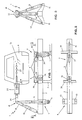
- Apparatus 1 comprises a horizontally extending base 2 consisting of a straight longitudinal member mounted on wheels.
- Base 2 is provided at one end 4 with anchoring means 5 for locking it to a repair bench 6 equipped with support legs 7 and carrying an accidented motor vehicle body, and at the other end 9 with a pair of supports 10 projecting sideways.
- Hinged to the supports 10 are a pair of double-acting hydraulic jacks 11 and 12 (more generally they can consist of any type of linear actuators) joined together at a junction point P which is raised relative to base 2.
- the rod 12a of the hydrualic jack 12 is substantially in the form of a fork and is hinged at 13 within a housing 14 formed on the sleeve-shaped end 15 of the rod 11a belonging to the other jack 11.
- Jacks 11 and 12 as disposed enable the junction point P to be continuously oriented with two degrees of freedom.
- a third double-acting hydraulic jack 16 is hinged to the second end 9 of the base 2 and connected to the junction point P so as to form, together with jacks 11 and 12, a substantially pyramidal structure with triangular base.
- the rod 16a of jack 16 ends in an arched slider 17 slidably fitted in a shaped structural element 18 having the form of a sector of a cercle and exhibiting two small arms hinged to the sleeve 15 ends. Due to the pyramidal structure thus formed it is possible to continuously orient point P in space with three degrees of freedom.
- the third jack 16 enables the straightening by drawing of the deformed part 21 of body 8 through the connection of point P to said deformed part, for example by means of a chain (not shown).
- a fourth double-acting hydraulic jack 22 fastened to point P and serving to execute the straightening of the deformed part 21 by a pulling or thrust action, in which case its rod 22a will be rigidly fixed to the deformed part 21.
- Fig. 1 there is a chain 23 interposed between the fourth jack 22 and the area 21. Obviously in this case the fourth jack 22 will only exert a pulling action.
- the correct orientation of the pulling direction is attained by merely operating jacks 11 and 12 and, it necessary, also the third jack 16, should one wish to modify the distance between point P and the area 21 for the purpose of utilizing the pulling equipments with the best results.
- the fourth jack 22 exhibits an arched slider 24 at the base thereof.
- Such slider is slidably fitted in an element having the form of a sector of a circle with two small arms 26 and 27 hinged to the ends of the sleeve 15.
- a graduated bar 28 integral with rod 22a and carrying a pair of friction-sliding washers 29 and 30, and interposed between said washers is a member 31, slidable along the bar 28 as well, which is integrally connected to the cylinder of jack 22.
- the third jack is replaced by a chain 32 (or similar member) which together with jacks 11 and 12 forms a pyramidal structure with triangular base.
- the apparatus 1 as regards the pulling group, consists of only three jacks, i.e. the pair of jacks 11 and 12 intended for orienting the pulling direction (with two degrees of freedom), and a third double-acting hydraulic jack 33 (quite similar to the fourth jack 22 in the preceding case) secured to point P and designed for carrying out the straightening of the deformed part 21.
- the previously described device involving a graduated bar 28 can be associated with said third jack 33.
- the anchoring means 5 consists of a fifth and a sixth jacks 34 and 35 each of them having a rod provided with a bracket 36 and 37 designed to engage in the corresponding longitudinal member 38 and 39 of the repair bench 6.
- the fifth jack 34 is fixed to the base 2 whereas the sixth jack 35 is movable relative to said base on which it can be adjusted in position being fitted in a rectilinear slit 40.
- the anchoring means 5 as structured enables the apparatus 1 to be easily positioned on the bench 6 at any desired position and without the bench being set in motion (raised or lowered).
- the apparatus 1 can be advantageously combined with a numerical control system and in particular with the apparatus being the subject of the European Patent Application No. 88830174.4 filed in the name of the same applicant and entitled "Apparatus to measure and/or check the position and orientation of characteristic spots or areas in structures, particularly in motor vehicle bodies".
- a piloted or automatic pulling action can be provided.
- jacks 11 and 12 and optionally jack 16 it is possible to automatically correct the pulling direction so that the apparatus 1 can straighten the deformed part 21 with the greatest accuracy. This result can be achieved by measuring the spot to be repaired by a position transducer.
- the apparatus disclosed in the above European application is applied to the deformed area 21 and chain 23 is used as a pulling member.
- the operator commands the operation of jacks 16, or 22 or 33 depending upon the structure of the apparatus 1, for the execution of a pulling action and automatically, as the pulling is carried out, the apparatus disclosed in the above mentioned European application No. 88830174.4 gives data relative to the displacements carried out by the deformed part 21.
- the equipment for straightening the deformed part 21 is set in motion and all operations are accomplished automatically.
- the apparatus 1 as conceived, either if operated manually or automatically, enables the pulling direction to be continuously modified (by shifting the junction point P), which brings about the possibility of orienting the pulling or thrust action in all directions within a solid angle defined by the possibilities of displacement of jacks 11 and 12, and optionally 16.
- the above described apparatus 1 is fed by a hydraulic control box (not shown for the sake of simplicity) and controlled by the operator through a hydraulic multi-outlet distributor (not shown too).
- apparatus 1 The main advantages attainable by the use of apparatus 1 are the following: - a reduced time in the application of apparatus 1 to the repair bench 6 and the possibility of positioning the apparatus relative to the bench according to the desired orientation (within some limits); - the possibility of covering a wide repair area with reference to the pulling or thrust directions, which can be horizontal or vertical and directed downwardly or upwardly, almost without the intervention of the operator; - the orientation of the repair direction is carried out by the use of hydraulic jacks (however other appropriate technically equivalent means can be used as well) and the intervention of the operator is only restrained to some commands through levers or pushbuttons.
- the operator is safer during his work because the junction point P (in case of use of the three jacks 11, 12 and 16) does not remarkably shift should the pulling chain break. If the fourth jack 22 (or third jack 33) located directly along the repair direction is used, the operator is still more safer because it it possible to surely restrain the load applied to the pulling chain 23.
- the invention attains the intended purposes.
- the apparatus may also adopt configurations that differ from those herein illustrated without however departing from the scope of the inventive idea characterizing it.
- all of the details may be replaced by technically equivalent elements and the sizes and materials used may be of any nature and magnitude in accordance with requirements.
Landscapes
- Engineering & Computer Science (AREA)
- Mechanical Engineering (AREA)
- Straightening Metal Sheet-Like Bodies (AREA)
- Vehicle Cleaning, Maintenance, Repair, Refitting, And Outriggers (AREA)
- Medicines Containing Antibodies Or Antigens For Use As Internal Diagnostic Agents (AREA)
- Pharmaceuticals Containing Other Organic And Inorganic Compounds (AREA)
- Medicines That Contain Protein Lipid Enzymes And Other Medicines (AREA)
Applications Claiming Priority (2)
| Application Number | Priority Date | Filing Date | Title |
|---|---|---|---|
| IT8497588 | 1988-12-22 | ||
| IT8884975A IT1226671B (it) | 1988-12-22 | 1988-12-22 | Apparecchiatura per la riparazione di scocche incidentate di autoveicoli |
Publications (2)
| Publication Number | Publication Date |
|---|---|
| EP0375630A2 true EP0375630A2 (de) | 1990-06-27 |
| EP0375630A3 EP0375630A3 (de) | 1991-07-03 |
Family
ID=11326728
Family Applications (1)
| Application Number | Title | Priority Date | Filing Date |
|---|---|---|---|
| EP19890830532 Withdrawn EP0375630A3 (de) | 1988-12-22 | 1989-12-01 | Vorrichtung zur Reparatur von beschädigten Fahrzeugkarosserien |
Country Status (5)
| Country | Link |
|---|---|
| US (1) | US5016464A (de) |
| EP (1) | EP0375630A3 (de) |
| AU (1) | AU618431B2 (de) |
| CA (1) | CA2004119A1 (de) |
| IT (1) | IT1226671B (de) |
Cited By (2)
| Publication number | Priority date | Publication date | Assignee | Title |
|---|---|---|---|---|
| EP0475344A1 (de) * | 1990-09-11 | 1992-03-18 | BLACKHAWK GmbH | Richtgerät |
| EP1228821A1 (de) * | 2001-02-04 | 2002-08-07 | Star Co., Ltd. | Vorrichtung zur Korrektur von Automobilkarosserieblechen |
Families Citing this family (15)
| Publication number | Priority date | Publication date | Assignee | Title |
|---|---|---|---|---|
| IT1266536B1 (it) * | 1993-04-08 | 1997-01-09 | Car Bench Spa | Braccio di trazione e di allineamento,particolarmente per banchi di riparazione della scocca di autoveicoli |
| ATE176413T1 (de) * | 1993-08-30 | 1999-02-15 | Mv Marketing & Vertriebs Gmbh | Vorrichtung zum beheben von schäden an autokarosserieteilen |
| US5916322A (en) * | 1995-09-26 | 1999-06-29 | Autorobot Finland Oy | Positioning device |
| US6834526B2 (en) * | 2001-06-11 | 2004-12-28 | Michael Marx | Hydraulic directional converter |
| US6820860B2 (en) | 2001-06-21 | 2004-11-23 | Jimmy V. Gordon | Vehicle body lifter |
| US6820456B2 (en) * | 2001-11-15 | 2004-11-23 | Delaware Capital Formation, Inc. | Vehicle-straightening bench with movable carriages for mounting pulling assemblies |
| US6765664B2 (en) * | 2002-01-09 | 2004-07-20 | Delaware Capital Formation, Inc. | Laser scanner with parabolic collector |
| US20040200258A1 (en) * | 2003-04-08 | 2004-10-14 | Hess Jeffrey A. | Locking mechanism for jack with elevated platform |
| EP1628787A4 (de) * | 2003-05-30 | 2007-04-25 | Chief Automotive Technologies | Mehrere bewegliche schlitten mit bahnen mit mehreren radien und geneigten rollen |
| US8402637B2 (en) * | 2008-11-04 | 2013-03-26 | Chief Automotive Technologies, Inc. | Vehicle fixture with alignment target |
| CN105730409B (zh) * | 2016-02-25 | 2017-12-22 | 吕继祥 | 重型车辆校正系统 |
| CN108580586A (zh) * | 2018-06-19 | 2018-09-28 | 南京工业职业技术学院 | 液压两用汽车凹痕修复器 |
| JP7347791B2 (ja) * | 2019-03-18 | 2023-09-20 | 株式会社エス企画 | 自動車ボデー修復装置 |
| CN111760936A (zh) * | 2020-06-30 | 2020-10-13 | 金燕 | 一种汽车钣金凹痕自动修复设备 |
| CN111879393B (zh) * | 2020-07-29 | 2022-05-31 | 梧州学院 | 一种称重传感器修复方法及系统 |
Family Cites Families (9)
| Publication number | Priority date | Publication date | Assignee | Title |
|---|---|---|---|---|
| US2151063A (en) * | 1937-08-30 | 1939-03-21 | Weaver Mfg Co | Automobile body repairing appliance |
| US3492855A (en) * | 1967-11-20 | 1970-02-03 | Cleyburn M Wylie | Body and frame straightening tool |
| US3667275A (en) * | 1970-02-25 | 1972-06-06 | Applied Power Ind Inc | Self-stabilizing force distributing apparatus |
| US3691817A (en) * | 1970-03-06 | 1972-09-19 | Robert P Friend | Mobile frame and body straightener |
| US3869767A (en) * | 1971-04-19 | 1975-03-11 | Applied Power Ind Inc | Method of reforming and straightening members |
| US4193203A (en) * | 1977-09-08 | 1980-03-18 | Applied Power Inc. | Method and apparatus for reforming and straightening vehicles |
| FR2409800A1 (fr) * | 1977-11-25 | 1979-06-22 | Couturier Alain | Support de verins multipositions |
| DE2834319A1 (de) * | 1978-08-04 | 1980-02-28 | Applied Power Inc | Richtgeraet |
| US4400968A (en) * | 1981-04-20 | 1983-08-30 | Barbieri Louis C | Apparatus for reforming deformed container structures and the like |
-
1988
- 1988-12-22 IT IT8884975A patent/IT1226671B/it active
-
1989
- 1989-11-27 US US07/442,296 patent/US5016464A/en not_active Expired - Fee Related
- 1989-11-29 CA CA002004119A patent/CA2004119A1/en not_active Abandoned
- 1989-12-01 EP EP19890830532 patent/EP0375630A3/de not_active Withdrawn
- 1989-12-11 AU AU46099/89A patent/AU618431B2/en not_active Ceased
Cited By (4)
| Publication number | Priority date | Publication date | Assignee | Title |
|---|---|---|---|---|
| EP0475344A1 (de) * | 1990-09-11 | 1992-03-18 | BLACKHAWK GmbH | Richtgerät |
| WO1992004141A1 (de) * | 1990-09-11 | 1992-03-19 | Blackhawk Gmbh | Richtgerät |
| EP1228821A1 (de) * | 2001-02-04 | 2002-08-07 | Star Co., Ltd. | Vorrichtung zur Korrektur von Automobilkarosserieblechen |
| US6679092B2 (en) | 2001-02-04 | 2004-01-20 | Star Co., Ltd. | Automobile sheet metal surface correcting equipment |
Also Published As
| Publication number | Publication date |
|---|---|
| IT8884975A0 (it) | 1988-12-22 |
| IT1226671B (it) | 1991-01-31 |
| AU4609989A (en) | 1990-06-28 |
| CA2004119A1 (en) | 1990-06-22 |
| US5016464A (en) | 1991-05-21 |
| AU618431B2 (en) | 1991-12-19 |
| EP0375630A3 (de) | 1991-07-03 |
Similar Documents
| Publication | Publication Date | Title |
|---|---|---|
| US5016464A (en) | Apparatus for repairing accident-damaged bodies in motor vehicles | |
| EP0686224B1 (de) | Grossmanipulator, insbesondere für autobetonpumpen | |
| US4813125A (en) | Method and apparatus for establishing the position of a datum reference from an object having dimensional variations within a tolerance range | |
| CA2857621C (en) | Curvature retaining device for plate-shaped workpiece, curvature retaining method for plate-shaped workpiece, and curvature forming method for plate-shaped workpiece | |
| EP2298508B1 (de) | Vermessung eines Manipulators | |
| EP2636634B1 (de) | Kran und Verfahren zur Kransteuerung | |
| EP1016495B1 (de) | Mehrzweckhaltevorrichtung | |
| US2559250A (en) | Automotive body and frame straightening apparatus | |
| GB2135626A (en) | Motor vehicle body repair bench | |
| CA2037598C (en) | Position seeking apparatus | |
| US4586359A (en) | Anchor element positioner apparatus for automobile body repair and realignment | |
| US4976026A (en) | Method and apparatus of establishing the position of a datum reference from an object having dimensional variations within a tolerance range | |
| US5706691A (en) | Stand supporting method and equipment thereof and a position measuring method of a supporting platform and equipment thereof for roll former | |
| FI71715B (fi) | Dubbelkommando foer fordonsburna arbetsredskap i synnerhet kranar | |
| US4254651A (en) | Device for bending metal objects | |
| EP0163216A2 (de) | Richtvorrichtung für Automobilkarosserie | |
| JPH0811379B2 (ja) | 教示装置 | |
| US4473954A (en) | Symmetric body | |
| US3044526A (en) | Brake for forming metal plate and sheet | |
| CN210024281U (zh) | 三维滑移定位夹具 | |
| EP0750533B1 (de) | Fahrzeugkarosserie-ausrichtungs- und messvorrichtung | |
| DE102022103419B3 (de) | Betätigungseinrichtung und Verfahren zur Betätigung einer Fahrwerkanordnung | |
| JP2741229B2 (ja) | 細径金属管の曲げ加工装置 | |
| US3478910A (en) | Tilt mechanism for mast assembly | |
| JPS6018934B2 (ja) | 引張圧縮疲労試験装置 |
Legal Events
| Date | Code | Title | Description |
|---|---|---|---|
| PUAI | Public reference made under article 153(3) epc to a published international application that has entered the european phase |
Free format text: ORIGINAL CODE: 0009012 |
|
| AK | Designated contracting states |
Kind code of ref document: A2 Designated state(s): DE ES FR GB SE |
|
| PUAL | Search report despatched |
Free format text: ORIGINAL CODE: 0009013 |
|
| AK | Designated contracting states |
Kind code of ref document: A3 Designated state(s): DE ES FR GB SE |
|
| 17P | Request for examination filed |
Effective date: 19911213 |
|
| 17Q | First examination report despatched |
Effective date: 19930917 |
|
| STAA | Information on the status of an ep patent application or granted ep patent |
Free format text: STATUS: THE APPLICATION IS DEEMED TO BE WITHDRAWN |
|
| 18D | Application deemed to be withdrawn |
Effective date: 19940128 |