EP0376038B1 - Tableau d'instruments éclairé - Google Patents
Tableau d'instruments éclairé Download PDFInfo
- Publication number
- EP0376038B1 EP0376038B1 EP89122828A EP89122828A EP0376038B1 EP 0376038 B1 EP0376038 B1 EP 0376038B1 EP 89122828 A EP89122828 A EP 89122828A EP 89122828 A EP89122828 A EP 89122828A EP 0376038 B1 EP0376038 B1 EP 0376038B1
- Authority
- EP
- European Patent Office
- Prior art keywords
- layer
- meter panel
- mark
- transparent
- base plate
- Prior art date
- Legal status (The legal status is an assumption and is not a legal conclusion. Google has not performed a legal analysis and makes no representation as to the accuracy of the status listed.)
- Expired - Lifetime
Links
- 230000000007 visual effect Effects 0.000 claims description 28
- 239000000126 substance Substances 0.000 claims description 25
- 239000003973 paint Substances 0.000 claims description 8
- 230000000903 blocking effect Effects 0.000 claims description 3
- 239000004033 plastic Substances 0.000 description 2
- 239000004417 polycarbonate Substances 0.000 description 2
- 229920000515 polycarbonate Polymers 0.000 description 2
- 238000010276 construction Methods 0.000 description 1
- 239000002184 metal Substances 0.000 description 1
Images

Classifications
-
- G—PHYSICS
- G01—MEASURING; TESTING
- G01D—MEASURING NOT SPECIALLY ADAPTED FOR A SPECIFIC VARIABLE; ARRANGEMENTS FOR MEASURING TWO OR MORE VARIABLES NOT COVERED IN A SINGLE OTHER SUBCLASS; TARIFF METERING APPARATUS; MEASURING OR TESTING NOT OTHERWISE PROVIDED FOR
- G01D11/00—Component parts of measuring arrangements not specially adapted for a specific variable
- G01D11/28—Structurally-combined illuminating devices
-
- B—PERFORMING OPERATIONS; TRANSPORTING
- B60—VEHICLES IN GENERAL
- B60Q—ARRANGEMENT OF SIGNALLING OR LIGHTING DEVICES, THE MOUNTING OR SUPPORTING THEREOF OR CIRCUITS THEREFOR, FOR VEHICLES IN GENERAL
- B60Q3/00—Arrangement of lighting devices for vehicle interiors; Lighting devices specially adapted for vehicle interiors
- B60Q3/10—Arrangement of lighting devices for vehicle interiors; Lighting devices specially adapted for vehicle interiors for dashboards
- B60Q3/14—Arrangement of lighting devices for vehicle interiors; Lighting devices specially adapted for vehicle interiors for dashboards lighting through the surface to be illuminated
-
- B—PERFORMING OPERATIONS; TRANSPORTING
- B60—VEHICLES IN GENERAL
- B60Q—ARRANGEMENT OF SIGNALLING OR LIGHTING DEVICES, THE MOUNTING OR SUPPORTING THEREOF OR CIRCUITS THEREFOR, FOR VEHICLES IN GENERAL
- B60Q3/00—Arrangement of lighting devices for vehicle interiors; Lighting devices specially adapted for vehicle interiors
- B60Q3/60—Arrangement of lighting devices for vehicle interiors; Lighting devices specially adapted for vehicle interiors characterised by optical aspects
- B60Q3/68—Arrangement of lighting devices for vehicle interiors; Lighting devices specially adapted for vehicle interiors characterised by optical aspects using ultraviolet light
-
- G—PHYSICS
- G01—MEASURING; TESTING
- G01D—MEASURING NOT SPECIALLY ADAPTED FOR A SPECIFIC VARIABLE; ARRANGEMENTS FOR MEASURING TWO OR MORE VARIABLES NOT COVERED IN A SINGLE OTHER SUBCLASS; TARIFF METERING APPARATUS; MEASURING OR TESTING NOT OTHERWISE PROVIDED FOR
- G01D11/00—Component parts of measuring arrangements not specially adapted for a specific variable
- G01D11/24—Housings ; Casings for instruments
- G01D11/26—Windows; Cover glasses; Sealings therefor
-
- Y—GENERAL TAGGING OF NEW TECHNOLOGICAL DEVELOPMENTS; GENERAL TAGGING OF CROSS-SECTIONAL TECHNOLOGIES SPANNING OVER SEVERAL SECTIONS OF THE IPC; TECHNICAL SUBJECTS COVERED BY FORMER USPC CROSS-REFERENCE ART COLLECTIONS [XRACs] AND DIGESTS
- Y10—TECHNICAL SUBJECTS COVERED BY FORMER USPC
- Y10S—TECHNICAL SUBJECTS COVERED BY FORMER USPC CROSS-REFERENCE ART COLLECTIONS [XRACs] AND DIGESTS
- Y10S116/00—Signals and indicators
- Y10S116/26—Light rod
-
- Y—GENERAL TAGGING OF NEW TECHNOLOGICAL DEVELOPMENTS; GENERAL TAGGING OF CROSS-SECTIONAL TECHNOLOGIES SPANNING OVER SEVERAL SECTIONS OF THE IPC; TECHNICAL SUBJECTS COVERED BY FORMER USPC CROSS-REFERENCE ART COLLECTIONS [XRACs] AND DIGESTS
- Y10—TECHNICAL SUBJECTS COVERED BY FORMER USPC
- Y10S—TECHNICAL SUBJECTS COVERED BY FORMER USPC CROSS-REFERENCE ART COLLECTIONS [XRACs] AND DIGESTS
- Y10S116/00—Signals and indicators
- Y10S116/36—Illuminated dial and pointer
Definitions
- the present invention relates in general to illuminated indicator gauges used, for example, as speedometers and tachometers for a motor vehicle or the like, and more particuarly to such gauges of a type which has a visual alarm indicator.
- the gauge comprises a meter panel 1 formed with circular openings 3a and 3b which have respective dial boards 2a and 2b received therein.
- the meter panel 1 has further two visual alarm indicators 4a and 4b mounted thereto and a turning direction indicator 5 mounted thereto.
- Fig. 4 shows in detail the meter panel 1 and each of the visual alarm indicators 4a and 4b mounted to the meter panel 1.
- the meter panel 1 comprises a transparent base plate 1a made of a rigid plastic, such as polycarbonate or the like, a transparent coloured layer 1b printed on a back surface of the base plate 1a and a smoked layer 1c printed on a front surface of the base plate 1a.
- the layer 1b is usually coloured red, blue or yellow.
- a fluorescent transparent substance layer 1d is coated on the smoked layer 1c except the portions with which the visual alarm indicators 4a and 4b and the turning direction indicator 5 are associated. As is known, the fluorescent substance layer 1d emits visible light under the action of ultraviolet rays.
- An electric ultraviolet lamp 10 is arranged in front of the meter panel 1.
- Each visual alarm indicator 4a or 4b comprises various opaque marks 1e printed on the smoked layer 1c, lamp housings 6 each having an open end connected to the back surface of the meter panel 1 at the position where the corresponding mark 1e is located, and alarm electric lamps 7 respectively installed in the lamp housings 6.
- the conventional gauge has the following drawbacks.
- the portions of the meter panel 1 where the visual alarm indicators 4a and 4b are positioned appear dark.
- This phenomenon makes the external view of the illuminated meter panel 1 poor.
- the difference in brightness between the illuminated portion of the meter panel 1 and the non-illuminated portions of the same sometimes causes difficulties to arise in clearly and quickly reading the indicia on the dial boards 2a and 2b.
- an indicator gauge which comprises a meter panel, the meter panel including a transparent base plate, a transparent colored layer applied to a rear surface of the transparent base plate and a fluorescent transparent substance layer, applied on a smoked layer which itself is applied to a front surface of the transparent base plate; a visual alarm indicator, including an opaque mark mounted to a given portion of the meter panel, a lamp housing having an open end which is connected to a rear surface of the meter panel in such a manner as to face toward the given portion and an electric lamp installed in the lamp housing; and an ultraviolet lamp arranged in front of the meter panel and generating ultraviolet rays upon electric energization thereof, wherein the fluorescent transparent substance layer is a continuous layer provided around the opaque mark.
- an indicator gauge which comprises a meter panel, the meter panel including a transparent base plate, a transparent colored layer applied to a rear surface of the transparent base plate and a fluorescent transparent substance layer, applied on a smoked layer which itself is applied to a front surface of the transparent base plate; a visual alarm indicator, including an opaque mark mounted to a given portion of the meter panel, a lamp housing having an open end which is connected to a rear surface of the meter panel in such a manner as to face toward the given portion and an electric lamp installed in the lamp housing; and an ultraviolet lamp arranged in front of the meter panel and generating ultraviolet rays upon electric energization thereof, wherein the fluorescent transparent substance layer is a continuous layer and is provided in at least one plane parallel to the plane in which the opaque mark is provided.
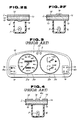
- FIG. 1 there is shown an illuminated indicator gauge of the present invention.
- the gauge of the invention comprises generally a meter panel 1 formed with circular openings 3a and 3b which have respective dial boards 2a and 2b received therein.
- the meter panel 1 has further two visual alarm indicators 4a and 4b mounted thereto and a turning direction indicator 5 mounted thereto.
- An electric ultraviolet lamp 10 is arranged in front of the meter panel 1.
- Fig. 2A shows in detail the meter panel 1 and each of the visual alarn indicators 4a and 4b, which are employed in a first embodiment of the present invention.
- the meter panel 1 comprises a transparent base plate 1a made of a rigid plastic such as polycarbonate or the like, a transparent coloured layer 1b printed on a back surface of the base plate 1a and a smoked layer 1c printed on a front surface of the base plate 1a.
- Each visual alarm indicator 4a or 4b comprises various opaque marks 1e printed on the smoked layer 1c, lamp housings 6 each having an open end connected to the back surface of the meter panel 1 at the position where the corresponding mark 1e is located, and electric alarm lamps 7 respectively received in the lamp housings 6.
- a fluorescent transparent substance layer 1d is coated on the opaque marks 1e as well as the smoked layer 1c, and the opaque marks 1e are made of a suitable light reflecting paint.
- Table-I shows the visibility of each mark 1e and the limited surrounding of the mark 1e which are exhibited when the corresponding alarm lamp 7 is ON and OFF in day time and night time.
- the entire outer surface of the meter panel 1 which includes the surfaces for the visual alarm indicators 4a and 4b, shows the colour of the smoked layer 1c, and only the marks 1e are illuminated whity due to reflection of natural light.
- the limited surrounding of the corresponding mark 1e is illuminated with a colour possessed by the transparent coloured layer 1b, and the mark 1e is shown like a silhouette (dark).
- the entire outer surface of the meter panel 1 which includes the surfaces for the visual alarm indicators 4a and 4b, is visionally illuminated under the action of the ultraviolet rays from the ultaviolet lamp 10, and the marks 1e are visionally illuminated with a colour possessed thereby.
- the limited surrounding of the corresponding mark 1e is illuminated with a colour which is provided by the combination of the colour of the fluorescent transparent substance layer 1d and the colour of the transparent coloured layer 1b, and the mark 1e is shown like a silhouette (dark).
- FIG. 2B there is shown a visual alarm indicator 4a or 4b which is employed in a second embodiment of the invention.
- opaque marks 1e made of a suitable light reflecting white paint are printed on a front surface of the transparent base plate 1a, and a smoked layer 1c is coated on the opaque marks 1e as well as the front surface of the base plate 1a.
- a fluorescent transparent substance layer 1d is coated on the smoked layer 1c.
- Table-II shows the visibility of each mark 1e and the limited surrounding of the mark 1e which are exhibited when the corresponding alarm lamp 7 is ON and OFF in day time and night time.
- the entire outer surface of the meter panel 1 which includes the surfaces for the visual alarm indicators 4a and 4b, shows the colour of the smoked layer 1c, and only the marks 1e are illuminated with a colour (gray) which is provided by the combination of the colour of the white marks 1e and the colour of the smoked layer 1c due to reflection of natural light.
- the limited surrounding of the corresponding mark 1e is illuminated with a colour possessed by the transparent coloured layer 1b, and the mark 1e is shown like a silhouette (dark).
- the entire outer surface of the meter panel 1 which includes the surfaces for the visual alarm indicators 4a and 4b, is visionally illuminated under the action of the ultraviolet rays from the ultraviolet lamp 10, and the marks 1e are out of sight.
- the limited surrounding of the corresponding mark 1e is illuminated with a colour which is provided by the combination of the colour of the fluorescent transparent substance layer 1d and the colour of the transparent coloured layer 1b, and the mark 1e is shown like a silhouette (dark).
- FIG. 2C there is shown a visual alarm indicator 4a or 4b which is employed in a third embodiment of the present invention.
- a smoked layer 1c is coated on the entire outer surface of the transparent base plate 1a.
- a fluorescent transparent substance layer 1d is coated on the entire outer surface of the smoked layer 1c.
- Opaque marks 1e made of a white paint are printed on an outer surface of the fluorescent layer 1d.
- Each mark 1e is coated with another fluorescent transparent substance layer 1d′ which emits light whose colour is different from that of the above-mentioned fluorescent layer 1d.
- Table-III shows the visibility of each mark 1e and the limited surrounding of the mark 1e which are exhibited when the corresponding alarm lamp 7 is ON and OFF in day time and night time.
- substantially entire outer surface of the meter panel 1 which includes the surfaces for the limited surroundings of the marks 1e, shows the colour of the smoked layer 1c, and only the marks 1e are illuminated whity due to reflection of natural light.
- the limited surrounding of the corresponding mark 1e is illuminated with a colour possessed by the transparent coloured layer 1b and the mark 1e is shown like a silhouetter (dark).
- the entire outer surface of the meter panel 1 which includes the surfaces for the visual alarm indicators 4a and 4b, is visionally illuminated under the action of the ultraviolet rays from the ultraviolet lamp 10, and the marks 1e are also visionally illuminated with a different colour.
- the limited surrounding of the corresponding mark 1e is illuminated with a colour which is provided by the combination of the colour of the fluorescent transparent substance layer 1d and the colour of the transparent coloured layer 1b, and the mark 1e is kept illuminated with the different colour.
- FIG. 2D there is shown a visual alarm indicator 4a or 4b which is employed in a fourth embodiment of the invention.
- a smoked layer 1c is coated on the entire outer surface of the transparent base plate 1a.
- a fluorescent transparent substance layer 1d is coated on the entire outer surface of the smoked layer 1c.
- Opaque marks 1e made of a white paint are printed on an outer surface of the fluorescent layer 1d.
- Table-IV shows the visibility of each mark 1e and the limited surrounding of the mark 1e which are exhibited when the corresponding alarm lamp 7 is ON and OFF in day time and night time.
- substantially entire outer surface of the meter panel 1 which includes the surfaces for the limited surroundings of the marks 1e, shows the colour of the smoked layer 1c, and only the marks 1e are illuminated whity due to reflection of natural light.
- the limited surrounding of the corresponding mark 1e is illuminated with a colour possessed by the transparent coloured layer 1b and the mark 1e is shown like a silhouetter (dark).
- substantially entire outer surface of the meter panel 1, which includes the limited surroundings of the marks 1e, is visionally illuminated under the action of the ultraviolet rays from the ultraviolet lamp 10, and each mark 1e is shown like a silhouette (dark).
- the limited surrounding of the corresponding mark 1e is illuminated with a colour which is provided by the combination of the colour of the fluorescent transparent substance layer 1d and the colour of the transparent coloured layer 1b, and the mark 1e is shown like a silhouette (dark).
- FIG. 2E there is shown a visual alarm indicator 4a or 4b which is employed in a fifth embodiment of the invention.
- opaque marks 1e made of a suitable light blocking paint are printed on the exposed surface of the transparent coloured layer 1b which is printed on the back surface of the transparent base plate 1a.
- a smoked layer 1c is coated on a front surface of the base plate 1a and a fluorescent transparent substance layer 1d is coated on the smoked layer 1c.
- Table-V shows the visibility of each mark 1e and the limited surrounding of the mark 1e which are exhibited when the corresponding alarm lamp 7 is ON and OFF in day time and night time.
- the entire outer surface of the meter panel 1 which includes the surfaces for the visual alarm indicators 4a and 4b, shows the colour of the smoked layer 1c and the marks 1e are out of sight.
- the limited surrounding of the corresponding mark 1e is illuminated with a colour passessed by the transparent coloured layer 1b, and the mark 1e is shown like a silhouette (dark).
- the entire outer surface of the meter panel 1 which includes the surfaces for the visual alarm indicators 4a and 4b, is visionally illuminated under the action of the ultraviolet rays from the ultraviolet lamp 10, and the marks 1e are out of sight.
- the limited surrounding of the corresponding mark 1e is illuminated with a colour which is provided by the combination of the coloure of the fluorescent transparent substance layer 1d and the colour of the transparent coloured layer 1b, and the mark 1e is shown like a silhouette (dark).
- FIG. 2F there is shown a visual alarm indicator 4a or 4b employed in a sixth embodiment of the present invention.
- the indicator in this embodiment is substantially the same as that in the second embodiment (Fig. 2B), except for the marks 1e. That is, the marks 1e in the sixth embodiment are made of a light blocking paint.
- each mark 1e and the limited surrounding of the mark 1e of this sixth embodiment are substantially the same as those of the second embodiment.
- the illuminated indicator gauge of the present invention has the following advantageous features.
- the substantially entire outer surface of the metal panel 1, which includes the surfaces for the visual alarm indicators 4a and 4b, is illuminated evenly by the action of the ultraviolet rays from the ultraviolet lamp 10, unlike in the case of the afore-mentioned conventional gauge of Figs. 3 and 4. That is, in the invention, the unsightly non-illuminated portions which would be caused by provision of the visual alarm indicators 4a and 4b do not appear on the illuminated meter panel 1. This improves the external view of the panel 1. For the same reason, clear and quick reading of the indicia on the dial boards 2a and 2b is assured in the invention.
Landscapes
- Physics & Mathematics (AREA)
- General Physics & Mathematics (AREA)
- Engineering & Computer Science (AREA)
- Mechanical Engineering (AREA)
- Illuminated Signs And Luminous Advertising (AREA)
Claims (10)
- Tableau d'instruments comprenant :
un panneau d'instruments de mesure (1), ledit panneau d'instruments de mesure (1) comprenant une plaque de base transparente (1a), une couche colorée transparente (1b) appliquée sur une surface arrière de ladite plaque de base transparente (1a) et une couche en substance transparente, fluorescente (1b), appliquée sur une couche fumée (10) qui est appliquée elle-même sur une surface avant de ladite plaque de base transparente (1a),
un indicateur visuel d'alarme (4a, 4b), comprenant une marque opaque montée sur une portion donnée dudit panneau d'instruments de mesure (1), un logement de lampe (6) possédant une extrémité ouverte qui est connectée à une surface arrière dudit panneau d'instruments de mesure (1) de façon à être dirigé vers ladite partie donnée, et une lampe électrique (7) installée dans ledit logement de lampe (6); et
une lampe ultraviolette (10) disposée devant ledit panneau d' instruments de mesure et produisant des rayons ultraviolets lors de l'excitation électrique de celle-ci,
caractérisé en ce que,
ladite couche en substance transparente fluorescente (1d) est une couche continue réalisée autour de la marque opaque (1e). - Tableau d'instruments comprenant :
un panneau d'instruments de mesure (1), ledit panneau d'instruments de mesure (1) comprenant une plaque de base transparente (1a), une couche colorée transparente (1b) appliquée à une surface arrière de ladite plaque de base transparente (1a) et une couche en substance transparente fluorescente (1d) appliquée sur une couche fumée (10), qui est appliquée elle-même sur une surface avant de ladite plaque de base transparente (1a),
un indicateur visuel d'alarme (4a, 4b) comprenant une marque opaque montée sur une partie donnée dudit panneau d'instruments de mesure (1), un logement de lampe (6) présentant une extrémité ouverte qui est connectée à une sur face arrière dudit panneau d'instruments de mesure (1) de manière à être orientée vers ladite partie donnée, et une lampe électrique (7) installée dans ledit logement de lampe (6); et
une lampe ultraviolette (10) disposée devant ledit panneau d'instruments de mesure et produisant des rayons ultraviolets lors de l'excitation électrique de celle-ci,
caractérisée en ce que
ladite couche en substance transparente fluorescente (1d) est une couche continue et est réalisée dans au moins un plan parallèle au plan dans lequel la marque opaque (1e) est réalisée. - Tableau d'instruments selon la revendication 1 ou 2, dans lequel ledit panneau d'instruments de mesure (1) présente une ouverture dans laquelle un cadran (2a, 2b) est installé.
- Tableau d'instruments selon la revendication 1, dans lequel ladite marque opaque (1e) est disposée entre ladite couche fumée (1c) et ladite couche en substance transparente flurescente (1d) (figure 2A).
- Tableau d'instruments selon la revendication 2, dans lequel ladite marque opaque (1e) est disposée entre ladite plaque de base transparente (1a) et ladite couche fumée (1c) (figure 2B).
- Tableau d'instruments selon la revendication 2, dans lequel ladite marque opaque (1e) est disposée sur ladite couche en substance transparente fluorescente (1d) (figure 2D).
- Tableau d'instruments selon la revendication 6, dans lequel ladite marque opaque (1e) reçoit à sa surface extérieure une autre couche en substance transparente fluorescente (1d) (figure 2C).
- Tableau d'instruments selon la revendication 2, dans lequel ladite marque opaque (1e) est disposée sur ladite couche colorée transparente (1b) de manière à être exposée à l'intérieur dudit logement de lampe (6) (figure 2E).
- Tableau d'instruments selon les revendications 4, 5, 6 ou 7, dans lequel ladite marque opaque (1e) est réalisée en une peinture blanche réfléchissant la lumière.
- Tableau d'instruments selon les revendications 1 ou 4, dans lequel ladite marque opaque (1e) est réalisée en une couleur formant blocage à la lumière.
Applications Claiming Priority (10)
| Application Number | Priority Date | Filing Date | Title |
|---|---|---|---|
| JP168747/88U | 1988-12-27 | ||
| JP16874988U JPH0289480U (fr) | 1988-12-27 | 1988-12-27 | |
| JP168750/88U | 1988-12-27 | ||
| JP16875088U JPH0289481U (fr) | 1988-12-27 | 1988-12-27 | |
| JP16874888U JPH0610387Y2 (ja) | 1988-12-27 | 1988-12-27 | 警報用表示板 |
| JP168746/88U | 1988-12-27 | ||
| JP16874688U JPH0289477U (fr) | 1988-12-27 | 1988-12-27 | |
| JP16874788U JPH0617179Y2 (ja) | 1988-12-27 | 1988-12-27 | 警報用表示板 |
| JP168749/88U | 1988-12-27 | ||
| JP168748/88U | 1988-12-27 |
Publications (2)
| Publication Number | Publication Date |
|---|---|
| EP0376038A1 EP0376038A1 (fr) | 1990-07-04 |
| EP0376038B1 true EP0376038B1 (fr) | 1993-10-06 |
Family
ID=27528463
Family Applications (1)
| Application Number | Title | Priority Date | Filing Date |
|---|---|---|---|
| EP89122828A Expired - Lifetime EP0376038B1 (fr) | 1988-12-27 | 1989-12-11 | Tableau d'instruments éclairé |
Country Status (3)
| Country | Link |
|---|---|
| US (2) | US5029046A (fr) |
| EP (1) | EP0376038B1 (fr) |
| DE (1) | DE68909765T2 (fr) |
Families Citing this family (31)
| Publication number | Priority date | Publication date | Assignee | Title |
|---|---|---|---|---|
| US5029046A (en) * | 1988-12-27 | 1991-07-02 | Kanto Seiki Co., Ltd. | Illuminated indicator gauge |
| JP2871802B2 (ja) * | 1990-04-19 | 1999-03-17 | アルプス電気株式会社 | 照光式キートツプ |
| JP2827149B2 (ja) * | 1992-10-20 | 1998-11-18 | 株式会社小糸製作所 | 安全表示装置 |
| US5504661A (en) * | 1994-07-05 | 1996-04-02 | Ford Motor Company | Translucent fluorescent filter for display panels |
| EP0691798A3 (fr) * | 1994-07-05 | 1996-07-17 | Ford Motor Co | Lampe fluorescente électroluminescente |
| US5734627A (en) * | 1996-11-27 | 1998-03-31 | Timex Corporation | Silhouette image on illuminated watch dial |
| US6517213B1 (en) * | 1997-03-31 | 2003-02-11 | Idec Izumi Corporation | Indicator device and illumination device |
| US6089893A (en) * | 1998-01-21 | 2000-07-18 | Leviton Manufacturing Co., Inc. | Illuminated electrical receptacle employing electroluminescent lamp member |
| US6068383A (en) * | 1998-03-02 | 2000-05-30 | Robertson; Roger | Phosphorous fluorescent light assembly excited by light emitting diodes |
| FR2779694B1 (fr) * | 1998-06-10 | 2000-08-11 | Sagem | Tableau de bord a eclairage polychrome |
| US6106127A (en) | 1999-03-19 | 2000-08-22 | Luminary Logic Ltd. | Illuminating device for watches, gauges and similar devices |
| US7283066B2 (en) * | 1999-09-15 | 2007-10-16 | Michael Shipman | Illuminated keyboard |
| US6918677B2 (en) * | 1999-09-15 | 2005-07-19 | Michael Shipman | Illuminated keyboard |
| US7172303B2 (en) * | 1999-09-15 | 2007-02-06 | Michael Shipman | Illuminated keyboard |
| US10013075B2 (en) | 1999-09-15 | 2018-07-03 | Michael Shipman | Illuminated keyboard |
| US20080143560A1 (en) * | 1999-09-15 | 2008-06-19 | Michael Shipman | Lightpipe for illuminating keys of a keyboard |
| US20090201179A1 (en) | 1999-09-15 | 2009-08-13 | Michael Shipman | Illuminated keyboard |
| US7193536B2 (en) * | 1999-09-15 | 2007-03-20 | Michael Shipman | Illuminated keyboard |
| US7193535B2 (en) * | 1999-09-15 | 2007-03-20 | Michael Shipman | Illuminated keyboard |
| CA2446630A1 (fr) | 2001-05-03 | 2002-11-14 | Luminary Logic Limited | Eclairage ultraviolet d'indication |
| JP3786033B2 (ja) * | 2001-10-31 | 2006-06-14 | 豊田合成株式会社 | メータ部表示システム |
| US6780331B2 (en) * | 2002-04-02 | 2004-08-24 | Science Applications International Corporation | Ozonation of contaminated liquids under high pressure |
| EP1627180A4 (fr) * | 2003-04-28 | 2009-10-21 | Michelle Jillian Fuwausa | Eclairage par ultraviolets de signes, d'horloges et d'instruments divers |
| US11216078B2 (en) | 2005-01-18 | 2022-01-04 | Michael Shipman | Illuminated keyboard |
| US8690368B1 (en) | 2005-08-22 | 2014-04-08 | Michael Shipman | Cavity filled lightpipe for illuminating keys of a keyboard |
| US20090091943A1 (en) * | 2007-10-05 | 2009-04-09 | Faurecia Interior Systems U.S.A., Inc. | Ambient Lighting Display |
| US8444309B2 (en) | 2010-08-13 | 2013-05-21 | Leviton Manufacturing Company, Inc. | Wiring device with illumination |
| JP5919507B2 (ja) * | 2011-09-13 | 2016-05-18 | パナソニックIpマネジメント株式会社 | 電子機器、発光ユニット、および透光パネル |
| FR3026691A1 (fr) * | 2014-10-02 | 2016-04-08 | Valeo Vision | Systeme d'eclairage et/ou de signalisation pour vehicules automobiles |
| DE102015222372A1 (de) * | 2015-11-12 | 2017-05-18 | Faurecia Innenraum Systeme Gmbh | Haut für ein Fahrzeuginnenverkleidungsteil und Fahrzeuginnenverkleidungsteil |
| US10398993B1 (en) * | 2017-04-24 | 2019-09-03 | William Mark Corporation | Floating phantom illusion |
Family Cites Families (10)
| Publication number | Priority date | Publication date | Assignee | Title |
|---|---|---|---|---|
| US3267598A (en) * | 1963-06-05 | 1966-08-23 | North American Aviation Inc | Internally illuminated matrix |
| US3499417A (en) * | 1967-06-07 | 1970-03-10 | Stewart Warner Corp | Translucent instrument dial means |
| FR2464856A1 (fr) * | 1979-09-06 | 1981-03-20 | Pons Rene | Conducteur de lumiere associe a un dispositif d'eclairage |
| FR2526736B1 (fr) * | 1982-05-12 | 1987-03-20 | Veglia E D | Tableau de bord de vehicule a temoin d'alerte |
| JPS62282225A (ja) * | 1986-05-30 | 1987-12-08 | Nippon Denso Co Ltd | 車両用計器装置 |
| EP0300592B1 (fr) * | 1987-06-29 | 1992-06-17 | Nippon Seiki Co. Ltd. | Appareil indicateur |
| US4845595A (en) * | 1987-07-31 | 1989-07-04 | Mitsubishi Jidosha Kogyo Kabushiki Kaisha | Meter device for vehicle |
| JPH01117596U (fr) * | 1988-02-03 | 1989-08-08 | ||
| US4882659A (en) * | 1988-12-21 | 1989-11-21 | Delco Electronics Corporation | Vacuum fluorescent display having integral backlit graphic patterns |
| US5029046A (en) * | 1988-12-27 | 1991-07-02 | Kanto Seiki Co., Ltd. | Illuminated indicator gauge |
-
1989
- 1989-12-01 US US07/443,332 patent/US5029046A/en not_active Expired - Fee Related
- 1989-12-11 DE DE89122828T patent/DE68909765T2/de not_active Expired - Fee Related
- 1989-12-11 EP EP89122828A patent/EP0376038B1/fr not_active Expired - Lifetime
-
1991
- 1991-04-12 US US07/684,565 patent/US5117334A/en not_active Expired - Fee Related
Also Published As
| Publication number | Publication date |
|---|---|
| DE68909765T2 (de) | 1994-01-27 |
| US5117334A (en) | 1992-05-26 |
| DE68909765D1 (de) | 1993-11-11 |
| EP0376038A1 (fr) | 1990-07-04 |
| US5029046A (en) | 1991-07-02 |
Similar Documents
| Publication | Publication Date | Title |
|---|---|---|
| EP0376038B1 (fr) | Tableau d'instruments éclairé | |
| US6409355B1 (en) | Combination instrument | |
| US6318872B1 (en) | Vehicle light meter having two colored layers with ring member dial | |
| US4457089A (en) | Decorative, illuminated automotive reflector | |
| US5044304A (en) | Illuminated indicator gauge | |
| US6904866B2 (en) | Indicator | |
| GB2139340A (en) | Light for motor vehicles | |
| US6511194B1 (en) | Pointer instrument | |
| US5142274A (en) | Silhouette illuminated vehicle head-up display apparatus | |
| US5130548A (en) | Indicator | |
| US5442526A (en) | Vehicle reflector illuminating system | |
| US5243194A (en) | Indicator | |
| US7030774B2 (en) | Floating visible indicator for an instrument cluster | |
| EP0367953B1 (fr) | Affichage éclairé pour automobile | |
| GB2266374A (en) | Display apparatus | |
| JP3215139B2 (ja) | 発光表示板装置 | |
| JPH0313063Y2 (fr) | ||
| JP3275283B2 (ja) | 透過照明式表示板 | |
| JP3468267B2 (ja) | 計器用表示装置 | |
| JPH04120990U (ja) | 透過照明式表示板 | |
| US3150456A (en) | Instrument panel lighting | |
| JP2568768Y2 (ja) | Led表示器 | |
| JPH0629686Y2 (ja) | 計器用文字板 | |
| JP2599858Y2 (ja) | 表示装置 | |
| JP2003014505A (ja) | 表示装置 |
Legal Events
| Date | Code | Title | Description |
|---|---|---|---|
| PUAI | Public reference made under article 153(3) epc to a published international application that has entered the european phase |
Free format text: ORIGINAL CODE: 0009012 |
|
| 17P | Request for examination filed |
Effective date: 19891211 |
|
| AK | Designated contracting states |
Kind code of ref document: A1 Designated state(s): DE FR GB IT |
|
| 17Q | First examination report despatched |
Effective date: 19910426 |
|
| GRAA | (expected) grant |
Free format text: ORIGINAL CODE: 0009210 |
|
| AK | Designated contracting states |
Kind code of ref document: B1 Designated state(s): DE FR GB IT |
|
| REF | Corresponds to: |
Ref document number: 68909765 Country of ref document: DE Date of ref document: 19931111 |
|
| ITF | It: translation for a ep patent filed | ||
| ET | Fr: translation filed | ||
| PLBE | No opposition filed within time limit |
Free format text: ORIGINAL CODE: 0009261 |
|
| STAA | Information on the status of an ep patent application or granted ep patent |
Free format text: STATUS: NO OPPOSITION FILED WITHIN TIME LIMIT |
|
| 26N | No opposition filed | ||
| PGFP | Annual fee paid to national office [announced via postgrant information from national office to epo] |
Ref country code: FR Payment date: 19961216 Year of fee payment: 8 |
|
| PG25 | Lapsed in a contracting state [announced via postgrant information from national office to epo] |
Ref country code: FR Free format text: THE PATENT HAS BEEN ANNULLED BY A DECISION OF A NATIONAL AUTHORITY Effective date: 19971231 |
|
| REG | Reference to a national code |
Ref country code: FR Ref legal event code: ST |
|
| PGFP | Annual fee paid to national office [announced via postgrant information from national office to epo] |
Ref country code: GB Payment date: 19981120 Year of fee payment: 10 |
|
| PGFP | Annual fee paid to national office [announced via postgrant information from national office to epo] |
Ref country code: DE Payment date: 19990127 Year of fee payment: 10 |
|
| PG25 | Lapsed in a contracting state [announced via postgrant information from national office to epo] |
Ref country code: GB Free format text: LAPSE BECAUSE OF NON-PAYMENT OF DUE FEES Effective date: 19991211 |
|
| GBPC | Gb: european patent ceased through non-payment of renewal fee |
Effective date: 19991211 |
|
| PG25 | Lapsed in a contracting state [announced via postgrant information from national office to epo] |
Ref country code: DE Free format text: LAPSE BECAUSE OF NON-PAYMENT OF DUE FEES Effective date: 20001003 |
|
| PG25 | Lapsed in a contracting state [announced via postgrant information from national office to epo] |
Ref country code: IT Free format text: LAPSE BECAUSE OF NON-PAYMENT OF DUE FEES;WARNING: LAPSES OF ITALIAN PATENTS WITH EFFECTIVE DATE BEFORE 2007 MAY HAVE OCCURRED AT ANY TIME BEFORE 2007. THE CORRECT EFFECTIVE DATE MAY BE DIFFERENT FROM THE ONE RECORDED. Effective date: 20051211 |