EP0376130A2 - Zweitaktbrennkraftmaschine - Google Patents
Zweitaktbrennkraftmaschine Download PDFInfo
- Publication number
- EP0376130A2 EP0376130A2 EP89123485A EP89123485A EP0376130A2 EP 0376130 A2 EP0376130 A2 EP 0376130A2 EP 89123485 A EP89123485 A EP 89123485A EP 89123485 A EP89123485 A EP 89123485A EP 0376130 A2 EP0376130 A2 EP 0376130A2
- Authority
- EP
- European Patent Office
- Prior art keywords
- intake passage
- oil
- reed valve
- crank chamber
- air
- Prior art date
- Legal status (The legal status is an assumption and is not a legal conclusion. Google has not performed a legal analysis and makes no representation as to the accuracy of the status listed.)
- Granted
Links
Images

Classifications
-
- F—MECHANICAL ENGINEERING; LIGHTING; HEATING; WEAPONS; BLASTING
- F01—MACHINES OR ENGINES IN GENERAL; ENGINE PLANTS IN GENERAL; STEAM ENGINES
- F01M—LUBRICATING OF MACHINES OR ENGINES IN GENERAL; LUBRICATING INTERNAL COMBUSTION ENGINES; CRANKCASE VENTILATING
- F01M1/00—Pressure lubrication
- F01M1/04—Pressure lubrication using pressure in working cylinder or crankcase to operate lubricant feeding devices
-
- F—MECHANICAL ENGINEERING; LIGHTING; HEATING; WEAPONS; BLASTING
- F01—MACHINES OR ENGINES IN GENERAL; ENGINE PLANTS IN GENERAL; STEAM ENGINES
- F01M—LUBRICATING OF MACHINES OR ENGINES IN GENERAL; LUBRICATING INTERNAL COMBUSTION ENGINES; CRANKCASE VENTILATING
- F01M3/00—Lubrication specially adapted for engines with crankcase compression of fuel-air mixture or for other engines in which lubricant is contained in fuel, combustion air, or fuel-air mixture
-
- F—MECHANICAL ENGINEERING; LIGHTING; HEATING; WEAPONS; BLASTING
- F02—COMBUSTION ENGINES; HOT-GAS OR COMBUSTION-PRODUCT ENGINE PLANTS
- F02B—INTERNAL-COMBUSTION PISTON ENGINES; COMBUSTION ENGINES IN GENERAL
- F02B1/00—Engines characterised by fuel-air mixture compression
- F02B1/02—Engines characterised by fuel-air mixture compression with positive ignition
- F02B1/04—Engines characterised by fuel-air mixture compression with positive ignition with fuel-air mixture admission into cylinder
-
- F—MECHANICAL ENGINEERING; LIGHTING; HEATING; WEAPONS; BLASTING
- F02—COMBUSTION ENGINES; HOT-GAS OR COMBUSTION-PRODUCT ENGINE PLANTS
- F02B—INTERNAL-COMBUSTION PISTON ENGINES; COMBUSTION ENGINES IN GENERAL
- F02B75/00—Other engines
- F02B75/02—Engines characterised by their cycles, e.g. six-stroke
- F02B2075/022—Engines characterised by their cycles, e.g. six-stroke having less than six strokes per cycle
- F02B2075/025—Engines characterised by their cycles, e.g. six-stroke having less than six strokes per cycle two
-
- F—MECHANICAL ENGINEERING; LIGHTING; HEATING; WEAPONS; BLASTING
- F02—COMBUSTION ENGINES; HOT-GAS OR COMBUSTION-PRODUCT ENGINE PLANTS
- F02B—INTERNAL-COMBUSTION PISTON ENGINES; COMBUSTION ENGINES IN GENERAL
- F02B75/00—Other engines
- F02B75/12—Other methods of operation
- F02B2075/125—Direct injection in the combustion chamber for spark ignition engines, i.e. not in pre-combustion chamber
-
- F—MECHANICAL ENGINEERING; LIGHTING; HEATING; WEAPONS; BLASTING
- F02—COMBUSTION ENGINES; HOT-GAS OR COMBUSTION-PRODUCT ENGINE PLANTS
- F02B—INTERNAL-COMBUSTION PISTON ENGINES; COMBUSTION ENGINES IN GENERAL
- F02B3/00—Engines characterised by air compression and subsequent fuel addition
- F02B3/06—Engines characterised by air compression and subsequent fuel addition with compression ignition
-
- Y—GENERAL TAGGING OF NEW TECHNOLOGICAL DEVELOPMENTS; GENERAL TAGGING OF CROSS-SECTIONAL TECHNOLOGIES SPANNING OVER SEVERAL SECTIONS OF THE IPC; TECHNICAL SUBJECTS COVERED BY FORMER USPC CROSS-REFERENCE ART COLLECTIONS [XRACs] AND DIGESTS
- Y02—TECHNOLOGIES OR APPLICATIONS FOR MITIGATION OR ADAPTATION AGAINST CLIMATE CHANGE
- Y02T—CLIMATE CHANGE MITIGATION TECHNOLOGIES RELATED TO TRANSPORTATION
- Y02T10/00—Road transport of goods or passengers
- Y02T10/10—Internal combustion engine [ICE] based vehicles
- Y02T10/12—Improving ICE efficiencies
-
- Y—GENERAL TAGGING OF NEW TECHNOLOGICAL DEVELOPMENTS; GENERAL TAGGING OF CROSS-SECTIONAL TECHNOLOGIES SPANNING OVER SEVERAL SECTIONS OF THE IPC; TECHNICAL SUBJECTS COVERED BY FORMER USPC CROSS-REFERENCE ART COLLECTIONS [XRACs] AND DIGESTS
- Y10—TECHNICAL SUBJECTS COVERED BY FORMER USPC
- Y10T—TECHNICAL SUBJECTS COVERED BY FORMER US CLASSIFICATION
- Y10T137/00—Fluid handling
- Y10T137/7722—Line condition change responsive valves
- Y10T137/7837—Direct response valves [i.e., check valve type]
- Y10T137/7879—Resilient material valve
- Y10T137/7888—With valve member flexing about securement
- Y10T137/7891—Flap or reed
Definitions
- the present invention relates to a 2-cycle engine having an oiling system employed for supplying lubricating oil directly to a point to be lubricated whereas air is supplied into the crank chamber through an intake passage containing a reed valve.
- an oiling system employed for supplying lubricating oil directly to a point to be lubricated whereas air is supplied into the crank chamber through an intake passage containing a reed valve.
- valve slapping noise of the reed valve is increased and/or the sealing ability of the reed valve is deteriorated as there are no damping deposits to absorb shocks and closing forces of the valve reed when the reeds are closed.
- the 2-cycle engine according to the present invention comprises an intake passage which is provided with an oil spray nozzle the nose portion of which opens into the intake passage upstream of said reed valve.
- the bottom portion of the crank chamber and the intake passage upstream of the reed valve are communicated with each other through a communicating passage provided with a check valve for preventing intake air from flowing from the intake passage into the crank chamber.
- the oil spray nozzle of the air intake passage supported by the air intake pipe which defines said air passage, opens nearly at a centre axis or middle portion of the cross section of the air intake passage in order to supply oil centrally with respect to the downstream reed valve.
- the seating noises of the reed valve can be reduced by the buffering action of this oil, and the sealing ability of the reed valve is heightened because the seating force of the valve reeds is increased by the oil, which securely prevents the air in the crank chamber from flowing back into the intake passage and thus restrains the engine performance from getting spoiled by such back flow.
- an oil spray nozzle is opened nearly at the middle of the intake passage, the above effect becomes more remarkable because the oil sprayed from the oil spray nozzle is uniformly supplied to the entire reed value.
- the 2-cycle engine concerned employs an oiling system for supplying lubricating oil only directly to points to be lubricated such as crank journal, connecting rod big end, etc.
- the actual oil supply by this system is restrained to its minimum required to reduce blue smoke in the engine exhaust gas and is far less than that by the separate oiling system.
- an oil discharging nozzle is provided in the intake passage upstream of the reed valve.
- said nozzle has a nose portion or opening which opens at the approximate centre of the intake passage with respect to the cross section thereof.
- a conduit is provided which connects the bottom of the crank case and the intake passage upstream of the reed valve, respectively, in order to supply deposits of lubricating oil from said bottom of the crank case to the air intake passage upstream of the reed valve.
- said conduit includes a check valve enabling lubricating oil to be transferred from the bottom of the crank case to a position inside the intake pipe of the intake passage upstream of the reed valve but prevents intake air from bypassing the reed valve and flowing directly into the crank case.
- the slapping noise of the reed valve is reduced and the sealing ability of the reed valve is improved due to the oil which is supplied upstream of the reed valve into the intake passage to become atomised and deposited on the seat surface of the valve seats of the reed valve to absorb shocks when the reed valve is closed.
- the nozzle opening of the oil spray nozzle supported by the intake pipe opens at approximately the centre axis of the intake passage.
- the distance A between a base portion of the reed valve and the outlet of the oil spray nozzle be in the order of 5 to 10 millimetres in order to assure optional atomization of the oil on the one hand and, preventing the oil droplets from depositing on the inside wall of the intake pipe on the other hand.
- oil is discharged from the nozzle during a suction stroke of the engine.
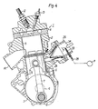
- FIG. 1 is a vertical cross-sectional view of a 2-cycle diesel engine according to this invention
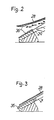
- Figs. 2 and 3 are cross-sectional views of the reed valve showing oil adhesion on the reed valve when the valve is opened and closed, respectively.
- the reference number 2 denotes a cylinder body disposed above the crankcase 3 on which body 2 is mounted a cylinder head 4.
- a cylinder 5 At the middle of the cylinder body 2 is formed a cylinder 5 in which is fitted a piston 6 slidably in the vertical direction.
- To the piston 6 is connected the small end of the connecting rod 6 through a piston pin 8, and the big end of the connecting rod 7 is connected to the web 9a of the crankshaft 9 through a crank pin 10.
- the crankshaft 9 is rotatably accommodated in the crank chamber 11 within the crankcase 3.
- the cylinder head 4 has a swirl chamber S formed within, into which are faced the tips of a fuel injection valve 12 and a glow plug 13 both mounted on the cylinder head 4 through screws.
- the fuel may be injected directly into the cylinder 5 by the fuel injection valve 12 without providing this swirl chamber S. Further, through the cylinder 5 wall is opened scavenging ports 14 and 15 and an exhaust port 16.
- each scavenging passage 17 or 18 is opened into the cylinder 5 through the scavenging port 14 or 15, respectively, and the other end thereof is opened into the crank chamber 11.
- One end of the exhaust passage 19 is opened into the cylinder 5 through the exhaust port 16, and to the other end thereof is connected an exhaust pipe (not shown).
- an intake passage 25 On one side of the cylinder body 2 is formed an intake passage 25 one end of which is opened into the crank chamber 11 and to the other end of which is connected an intake pipe 26.
- a reed valve 27 constructed with elastically flexible reeds 28, valve seats 29 on which the reeds 28 are to be seated and stoppers 30 for limiting the opening of the reeds 28 to permit air flow only toward the crank chamber 11.
- an oil spray nozzle 33 is installed through the intake pipe 26 wall and is opened at the middle of the intake passage 34 of the intake pipe 26 upstream of the reed valve 27.
- a preferred distance between the reed valve (more precisely a mounting base portion 37 thereof) and the nose portion centre axis of the oil spray nozzle amounts to 5 to 10 millimetres. If the distance is reduced exceedingly the atomization of the discharged oil were deteriorated whereas an exceedingly increased distance could result in the oil droplets being undesirably deposited on the inside wall of the intake pipe upstream of the reed valve without performing the objectives of said oil supply.
- This nozzle 33 and the check valve 32 are connected with each other through a pipe 35 communicating the crank chamber 11 with the intake passage 34 upstream of the reed valve 27 through the check valve 32.
- the check valve 32 is employed to prevent air from flowing from the intake passage 34 into the crank chamber 11 directly through the pipe 35 while permitting, as described later, the oil accumulated in the bottom of the crank chamber 11 to flow only toward the oil spray nozzle 33.
- an oil pump (not shown) directly supplies required minimum amount of oil to the points to be lubricated such as crankshaft 9 journals, connecting rod 7 big end, rubbing portion of the cylinder 5 against the piston 6, etc., and part of this supplied oil is, after passing through lubricating points, accumulated in the bottom of the crank chamber 11.
- the seating noise of the reed 28 can be reduced by the buffering action of the oil 36.
- the sealing ability of the reed valve 27 is heightened because the seating force of the valve reed 28 is increased by the oil 36 between the valve reed 28 and the valve seat 29, and thus the air in the crank chamber 11 is securely prevented from flowing back into the intake passage 25 through the reed valve 27, the engine performance deterioration is restrained.
- the oil spray nozzle 33 is opened nearly at the middle of the intake passage 34, the above effects become more remarkable because the oil sprayed from the oil spray nozzle 33 is uniformly supplied to the entire reed valve 27.
- the engine concerned 1 employs an oiling system for supplying lubricating oil only directly to points to be lubricated as described above, since the actual oil supply by this system is little as compared with that by the separate oiling system, and further since the lubricating oil accumulated in the crank chamber 11 bottom is recycled into the intake passage 34 upstream of the reed valve 27 utilizing the pressure within the crank chamber 11 in this embodiment, the amount of oil combusted together with fuel becomes very small, which is very advantageous for the exhaust gas blue smoke problem.
- the oil spray nozzle 33 installed through the intake pipe 26 wall and opened at the middle of the intake passage 34 upstream of the reed valve 27 as in the first embodiment, is directly connected with the oil pump P through a pipe 35.
- oil supplied by the oil pump P to and sprayed from the oil spray nozzle 33 flows together with air to be applied on the reed valve 27, and noise reduction and sealing ability heightening of the reed valve 27 can be obtained.
- the amount of oil to be supplied to the reed valve 27 may be small to a degree sufficient for applying on the reed valve 27.
- the 2-cycle system engine 1 incorporated with this second embodiment also employs an oiling system for supplying lubricating oil only directly to points to be lubricated as in the first embodiment, since the actual oil supply by this system is little as described above and the oil supply from the nozzle 33 to the reed valve is also little, there is no trouble for coping with the blue smoke of the exhaust gas.
Landscapes
- Engineering & Computer Science (AREA)
- Mechanical Engineering (AREA)
- General Engineering & Computer Science (AREA)
- Lubrication Of Internal Combustion Engines (AREA)
Applications Claiming Priority (2)
| Application Number | Priority Date | Filing Date | Title |
|---|---|---|---|
| JP63326012A JP2694907B2 (ja) | 1988-12-26 | 1988-12-26 | 2サイクルエンジン |
| JP326012/88 | 1988-12-26 |
Publications (3)
| Publication Number | Publication Date |
|---|---|
| EP0376130A2 true EP0376130A2 (de) | 1990-07-04 |
| EP0376130A3 EP0376130A3 (en) | 1990-09-05 |
| EP0376130B1 EP0376130B1 (de) | 1993-03-10 |
Family
ID=18183111
Family Applications (1)
| Application Number | Title | Priority Date | Filing Date |
|---|---|---|---|
| EP19890123485 Expired - Lifetime EP0376130B1 (de) | 1988-12-26 | 1989-12-19 | Zweitaktbrennkraftmaschine |
Country Status (4)
| Country | Link |
|---|---|
| US (1) | US4970996A (de) |
| EP (1) | EP0376130B1 (de) |
| JP (1) | JP2694907B2 (de) |
| DE (1) | DE68905316T2 (de) |
Cited By (5)
| Publication number | Priority date | Publication date | Assignee | Title |
|---|---|---|---|---|
| GB2270540A (en) * | 1992-09-10 | 1994-03-16 | Ford Motor Co | Lubrication of two-stroke i. c. engines. |
| US5375573A (en) * | 1993-09-09 | 1994-12-27 | Ford Motor Company | Lubrication of two-stroke internal combustion engines |
| DE4421132A1 (de) * | 1994-06-16 | 1995-12-21 | Ford Werke Ag | Zweitaktmotor mit Restölrückführung |
| EP0775813A1 (de) * | 1995-11-24 | 1997-05-28 | Yamaha Hatsudoki Kabushiki Kaisha | Brennkraftmaschine |
| AT411091B (de) * | 2000-11-30 | 2003-09-25 | Kirchberger Roland Dipl Ing | Viertakt-verbrennungsmotor |
Families Citing this family (13)
| Publication number | Priority date | Publication date | Assignee | Title |
|---|---|---|---|---|
| US5020484A (en) * | 1989-11-06 | 1991-06-04 | Fuji Jukogyo Kabushiki Kaisha | Lubricating system for a two-cycle engine |
| US5193500A (en) * | 1991-02-11 | 1993-03-16 | Outboard Marine Corporation | Oiling system for internal combustion engine |
| US5190121A (en) * | 1991-10-31 | 1993-03-02 | General Motors Corporation | Two phase compressor lubrication |
| JPH0617659A (ja) * | 1992-07-06 | 1994-01-25 | Yamaha Motor Co Ltd | エンジンの吸気用逆止弁 |
| JPH06193451A (ja) * | 1992-12-22 | 1994-07-12 | Yamaha Motor Co Ltd | 2サイクルエンジン |
| US5245956A (en) * | 1993-01-11 | 1993-09-21 | Barry Davidson | Reed valve assembly |
| US5351660A (en) * | 1993-07-01 | 1994-10-04 | Michael Logozzo | Electrically activated dynamic valve for spark ignition engines |
| US5471958A (en) * | 1993-07-27 | 1995-12-05 | Outboard Marine Corporation | Internal combustion engine with lubricating oil supply system |
| JPH10194195A (ja) * | 1996-12-28 | 1998-07-28 | Yamaha Motor Co Ltd | 小型船舶 |
| ITPZ20030001A1 (it) * | 2003-05-29 | 2004-11-30 | Enrico Nino | Sistema di combustione stratificato per motori alternativi |
| US7198020B1 (en) | 2006-03-13 | 2007-04-03 | Steven G Beddick | Lubrication systems and methods for an internal combustion engine |
| US10465638B2 (en) | 2017-05-24 | 2019-11-05 | Ktm Ag | Inlet manifold arrangement for a four-stroke combustion engine |
| CN115163245A (zh) * | 2022-05-31 | 2022-10-11 | 中国北方发动机研究所(天津) | 柴油机气门座圈润滑装置 |
Family Cites Families (8)
| Publication number | Priority date | Publication date | Assignee | Title |
|---|---|---|---|---|
| JPS5713224A (en) * | 1980-06-28 | 1982-01-23 | Yamaha Motor Co Ltd | Intake system of internal combustion engine |
| JPS5713222A (en) * | 1980-06-28 | 1982-01-23 | Yamaha Motor Co Ltd | Intake system of engine |
| JPS60145231U (ja) * | 1984-03-09 | 1985-09-26 | 株式会社 共立 | リ−ドバルブ |
| AT404055B (de) * | 1985-07-25 | 1998-08-25 | Avl Ges Fuer Verbrennungkraftm | Einzylinder-zweitakt-brennkraftmaschine mit kurbelkastenspülung |
| US4774918A (en) * | 1986-01-24 | 1988-10-04 | Mazda Motor Corporation | Engine lubricating system |
| IT1198062B (it) * | 1986-10-22 | 1988-12-21 | Piaggio & C Spa | Motore a combustione interna a due tempi,ad iniezione di combustibile ed accensione comandata |
| US4779581A (en) * | 1987-10-26 | 1988-10-25 | Outboard Marine Corporation | Dual fuel injection system for two stroke internal combustion engine |
| US4821688A (en) * | 1988-07-12 | 1989-04-18 | Brunswick Corporation | Automatic oil-fuel mixer with auxiliary chamber |
-
1988
- 1988-12-26 JP JP63326012A patent/JP2694907B2/ja not_active Expired - Fee Related
-
1989
- 1989-12-19 EP EP19890123485 patent/EP0376130B1/de not_active Expired - Lifetime
- 1989-12-19 DE DE8989123485T patent/DE68905316T2/de not_active Expired - Lifetime
- 1989-12-26 US US07/456,353 patent/US4970996A/en not_active Expired - Lifetime
Cited By (8)
| Publication number | Priority date | Publication date | Assignee | Title |
|---|---|---|---|---|
| GB2270540A (en) * | 1992-09-10 | 1994-03-16 | Ford Motor Co | Lubrication of two-stroke i. c. engines. |
| GB2270540B (en) * | 1992-09-10 | 1995-07-19 | Ford Motor Co | Lubrication of two-stroke internal combustion engines |
| US5375573A (en) * | 1993-09-09 | 1994-12-27 | Ford Motor Company | Lubrication of two-stroke internal combustion engines |
| DE4421132A1 (de) * | 1994-06-16 | 1995-12-21 | Ford Werke Ag | Zweitaktmotor mit Restölrückführung |
| EP0775813A1 (de) * | 1995-11-24 | 1997-05-28 | Yamaha Hatsudoki Kabushiki Kaisha | Brennkraftmaschine |
| US5709186A (en) * | 1995-11-24 | 1998-01-20 | Yamaha Hatsudoki Kabushiki Kaisha | Lubrication device for crank chamber supercharged engine |
| AT411091B (de) * | 2000-11-30 | 2003-09-25 | Kirchberger Roland Dipl Ing | Viertakt-verbrennungsmotor |
| US7073482B2 (en) | 2000-11-30 | 2006-07-11 | Roland Kirchberger | Four-cycle internal combustion engine |
Also Published As
| Publication number | Publication date |
|---|---|
| EP0376130A3 (en) | 1990-09-05 |
| EP0376130B1 (de) | 1993-03-10 |
| DE68905316T2 (de) | 1993-06-17 |
| DE68905316D1 (de) | 1993-04-15 |
| JPH02173315A (ja) | 1990-07-04 |
| US4970996A (en) | 1990-11-20 |
| JP2694907B2 (ja) | 1997-12-24 |
Similar Documents
| Publication | Publication Date | Title |
|---|---|---|
| EP0376130B1 (de) | Zweitaktbrennkraftmaschine | |
| US6055959A (en) | Engine supercharged in crankcase chamber | |
| EP0381201B1 (de) | Zweitaktbrennkraftmaschine mit Einrichtung zur direkten Schmierung | |
| US4945864A (en) | Two cycle engine piston lubrication | |
| EP1170470B1 (de) | Brennkraftmaschine | |
| US5052355A (en) | Lubrication system for two cycle engine | |
| US5396867A (en) | Two-cycle engine | |
| US5657724A (en) | Internal combustion engine construction | |
| US6378483B1 (en) | Lubrication system for four-stroke engine | |
| US4414929A (en) | Lubrication system for two-cycle internal combustion engines | |
| US5193500A (en) | Oiling system for internal combustion engine | |
| US4712532A (en) | Crankcase emission control system for an internal combustion engine | |
| EP0937920A1 (de) | Lageranordnung für einen Kolbenbolzen | |
| US6401701B1 (en) | Four-stroke cycle internal combustion engine | |
| US3753425A (en) | Two stroke internal combustion engines | |
| US5701856A (en) | Separate oiling type two cycle engine | |
| EP0747253A2 (de) | Montageanordnung von Zweitaktdieselbrennkraftmaschinen in einem Fahrzeug | |
| JP3206283B2 (ja) | エンジンの潤滑装置 | |
| JPH01277612A (ja) | 内燃機関の潤滑装置 | |
| JPS6313378Y2 (de) | ||
| JPH0429076Y2 (de) | ||
| JP2915293B2 (ja) | エンジン | |
| JPH02125961A (ja) | 2サイクル内燃機関用燃料供給装置 | |
| KR100210672B1 (ko) | 터보 차저 윤활부 구조 | |
| JPS6116218A (ja) | 内燃機関のオイル消費低減装置 |
Legal Events
| Date | Code | Title | Description |
|---|---|---|---|
| PUAI | Public reference made under article 153(3) epc to a published international application that has entered the european phase |
Free format text: ORIGINAL CODE: 0009012 |
|
| AK | Designated contracting states |
Kind code of ref document: A2 Designated state(s): DE FR GB IT |
|
| PUAL | Search report despatched |
Free format text: ORIGINAL CODE: 0009013 |
|
| AK | Designated contracting states |
Kind code of ref document: A3 Designated state(s): DE FR GB IT |
|
| 17P | Request for examination filed |
Effective date: 19901224 |
|
| 17Q | First examination report despatched |
Effective date: 19910402 |
|
| GRAA | (expected) grant |
Free format text: ORIGINAL CODE: 0009210 |
|
| AK | Designated contracting states |
Kind code of ref document: B1 Designated state(s): DE FR GB IT |
|
| REF | Corresponds to: |
Ref document number: 68905316 Country of ref document: DE Date of ref document: 19930415 |
|
| ITF | It: translation for a ep patent filed | ||
| ET | Fr: translation filed | ||
| PLBE | No opposition filed within time limit |
Free format text: ORIGINAL CODE: 0009261 |
|
| STAA | Information on the status of an ep patent application or granted ep patent |
Free format text: STATUS: NO OPPOSITION FILED WITHIN TIME LIMIT |
|
| 26N | No opposition filed | ||
| REG | Reference to a national code |
Ref country code: GB Ref legal event code: 746 Effective date: 19980331 |
|
| REG | Reference to a national code |
Ref country code: FR Ref legal event code: D6 |
|
| REG | Reference to a national code |
Ref country code: GB Ref legal event code: IF02 |
|
| PG25 | Lapsed in a contracting state [announced via postgrant information from national office to epo] |
Ref country code: IT Free format text: LAPSE BECAUSE OF NON-PAYMENT OF DUE FEES;WARNING: LAPSES OF ITALIAN PATENTS WITH EFFECTIVE DATE BEFORE 2007 MAY HAVE OCCURRED AT ANY TIME BEFORE 2007. THE CORRECT EFFECTIVE DATE MAY BE DIFFERENT FROM THE ONE RECORDED. Effective date: 20051219 |
|
| PGFP | Annual fee paid to national office [announced via postgrant information from national office to epo] |
Ref country code: FR Payment date: 20061208 Year of fee payment: 18 |
|
| REG | Reference to a national code |
Ref country code: FR Ref legal event code: ST Effective date: 20081020 |
|
| PG25 | Lapsed in a contracting state [announced via postgrant information from national office to epo] |
Ref country code: FR Free format text: LAPSE BECAUSE OF NON-PAYMENT OF DUE FEES Effective date: 20071231 |
|
| PGFP | Annual fee paid to national office [announced via postgrant information from national office to epo] |
Ref country code: DE Payment date: 20081211 Year of fee payment: 20 |
|
| PGFP | Annual fee paid to national office [announced via postgrant information from national office to epo] |
Ref country code: GB Payment date: 20081217 Year of fee payment: 20 |
|
| REG | Reference to a national code |
Ref country code: GB Ref legal event code: PE20 Expiry date: 20091218 |
|
| PG25 | Lapsed in a contracting state [announced via postgrant information from national office to epo] |
Ref country code: GB Free format text: LAPSE BECAUSE OF EXPIRATION OF PROTECTION Effective date: 20091218 |