EP0376173A2 - Lampe à décharge de type lueur ayant deux anodes et circuit pour l'alimenter - Google Patents
Lampe à décharge de type lueur ayant deux anodes et circuit pour l'alimenter Download PDFInfo
- Publication number
- EP0376173A2 EP0376173A2 EP89123698A EP89123698A EP0376173A2 EP 0376173 A2 EP0376173 A2 EP 0376173A2 EP 89123698 A EP89123698 A EP 89123698A EP 89123698 A EP89123698 A EP 89123698A EP 0376173 A2 EP0376173 A2 EP 0376173A2
- Authority
- EP
- European Patent Office
- Prior art keywords
- cathode electrode
- anode electrodes
- discharge lamp
- set forth
- lamp
- Prior art date
- Legal status (The legal status is an assumption and is not a legal conclusion. Google has not performed a legal analysis and makes no representation as to the accuracy of the status listed.)
- Withdrawn
Links
- 230000009977 dual effect Effects 0.000 title 1
- 238000004804 winding Methods 0.000 claims description 17
- 239000003990 capacitor Substances 0.000 claims description 16
- 230000008878 coupling Effects 0.000 claims description 4
- 238000010168 coupling process Methods 0.000 claims description 4
- 238000005859 coupling reaction Methods 0.000 claims description 4
- OAICVXFJPJFONN-UHFFFAOYSA-N Phosphorus Chemical compound [P] OAICVXFJPJFONN-UHFFFAOYSA-N 0.000 claims description 2
- 239000011248 coating agent Substances 0.000 claims description 2
- 238000000576 coating method Methods 0.000 claims description 2
- QSHDDOUJBYECFT-UHFFFAOYSA-N mercury Chemical compound [Hg] QSHDDOUJBYECFT-UHFFFAOYSA-N 0.000 claims description 2
- 229910052753 mercury Inorganic materials 0.000 claims description 2
- 229910052756 noble gas Inorganic materials 0.000 claims description 2
- 238000010438 heat treatment Methods 0.000 abstract description 6
- 230000001939 inductive effect Effects 0.000 description 7
- 230000008901 benefit Effects 0.000 description 5
- 230000004048 modification Effects 0.000 description 2
- 238000012986 modification Methods 0.000 description 2
- 238000010521 absorption reaction Methods 0.000 description 1
- 230000015556 catabolic process Effects 0.000 description 1
- 238000010276 construction Methods 0.000 description 1
- 238000010586 diagram Methods 0.000 description 1
- 238000010891 electric arc Methods 0.000 description 1
- 238000012423 maintenance Methods 0.000 description 1
- 239000000463 material Substances 0.000 description 1
- 229910052751 metal Inorganic materials 0.000 description 1
- 239000002184 metal Substances 0.000 description 1
- 229910052754 neon Inorganic materials 0.000 description 1
- GKAOGPIIYCISHV-UHFFFAOYSA-N neon atom Chemical compound [Ne] GKAOGPIIYCISHV-UHFFFAOYSA-N 0.000 description 1
- 230000010355 oscillation Effects 0.000 description 1
- 230000005855 radiation Effects 0.000 description 1
- 239000007858 starting material Substances 0.000 description 1
- 230000001131 transforming effect Effects 0.000 description 1
- 230000007704 transition Effects 0.000 description 1
Images

Classifications
-
- H—ELECTRICITY
- H05—ELECTRIC TECHNIQUES NOT OTHERWISE PROVIDED FOR
- H05B—ELECTRIC HEATING; ELECTRIC LIGHT SOURCES NOT OTHERWISE PROVIDED FOR; CIRCUIT ARRANGEMENTS FOR ELECTRIC LIGHT SOURCES, IN GENERAL
- H05B41/00—Circuit arrangements or apparatus for igniting or operating discharge lamps
- H05B41/14—Circuit arrangements
- H05B41/16—Circuit arrangements in which the lamp is fed by DC or by low-frequency AC, e.g. by 50 cycles/sec AC, or with network frequencies
- H05B41/20—Circuit arrangements in which the lamp is fed by DC or by low-frequency AC, e.g. by 50 cycles/sec AC, or with network frequencies having no starting switch
- H05B41/23—Circuit arrangements in which the lamp is fed by DC or by low-frequency AC, e.g. by 50 cycles/sec AC, or with network frequencies having no starting switch for lamps not having an auxiliary starting electrode
- H05B41/232—Circuit arrangements in which the lamp is fed by DC or by low-frequency AC, e.g. by 50 cycles/sec AC, or with network frequencies having no starting switch for lamps not having an auxiliary starting electrode for low-pressure lamps
- H05B41/2325—Circuit arrangements in which the lamp is fed by DC or by low-frequency AC, e.g. by 50 cycles/sec AC, or with network frequencies having no starting switch for lamps not having an auxiliary starting electrode for low-pressure lamps provided with pre-heating electrodes
Definitions
- the present invention relates in general to ballast circuits for lamps, and pertains, more particularly, to electronic ballast circuits, particularly for use with electric discharge lamps (e.g., glow discharge lamps having two anodes).
- electric discharge lamps e.g., glow discharge lamps having two anodes.
- An electric discharge lamp such as a glow lamp
- a glow lamp is essentially a low voltage (10-15 volt) discharge device.
- a significant discharge current has to be provided by a corresponding ballast device in order to obtain a reasonable lamp wattage, such as a wattage in the range of at least 20-30 watts.
- One such ballast device is an inductive ballast that typically drops about 80% of the line voltage across the ballast element.
- an inductive ballast is highly inefficient. For example, in the particular case of a 15 volt high current negative glow lamp, undesirably, substantially all of the RMS line voltage would be dropped across the ballast element.
- inductive ballasts can be designed so that resistive and magnetic power losses are minimized.
- a capacitive ballast is preferred.
- a capacitive ballast has also been employed with a bridge rectifier for use with arc discharge lamps.
- a bridge rectifier for use with arc discharge lamps.
- this article refer in particular to the circuit of FIG. 17 employing the combination of a bridge rectifier and capacitor ballast.
- FIG. 1 illustrates the ballast element as capacitor C.
- the full wave rectifier bridge is comprised of diodes D1-D4 interconnected in the normal bridge rectifier configuration.
- the input AC signal which typically is a 120 volt AC signal is coupled at the terminals 10.
- the terminals 10 connect in series with the capacitor C to the input of the full-wave rectifier bridge.
- the output of the full-wave rectifier bridge may be considered as coupling to the glow discharge lamp 12.
- the glow discharge lamp 12 is comprised of an anode 14 and a cathode 16. Also illustrated in FIG. 1 is the switch 20.
- the switch 20 couples, in one position thereof, across the cathode 16.
- the operation of the switch 20 is well known and is operable for lamp starting. Refer, for example, to similar starting switch configurations found in U.S. Patent No. 2,356,369 or U.S. Patent No. 4,288,725 previously referred to.
- One of the drawbacks associated with the electronic ballast circuit of FIG. 1 is the characteristic of the circuit of operating with a single hot spot operation regime for the lamp cathode. This is illustrated by the arrows 18 in FIG. 1. In essence, the discharge current flows to the same point on the cathode, as illustrated by arrows 18, during each half cycle of the AC signal.
- Another drawback associated with the electronic ballast circuit of FIG. 1 has to do with cost and associated power consumption considerations.
- cost and associated power consumption considerations For a typical glow lamp with a two amp discharge current and a line voltage of 120 volts there is a requirement for a relatively large capacitor on the order of 50 microfarads.
- diode losses are the considerable part of the total power which is on the order of 3-5 watts.
- cost of four high current, high voltage diodes is not insignificant.
- Still a further disadvantage of the electronic ballast circuit of FIG. 1 is the absence of a filament preheat during lamp operation as well as need of reswitching the lamp from starting to operation regime.
- U.S. Patent No. 4,518,897 which issued to Proud et al On May 21, 1985, relates to a lamp having a cathode electrode and a pair of anodes. Each of the anodes are connected to respective ends of the cathode electrode.
- an object of the present invention to provide an improved electronic ballast circuit, particularly an electronic ballast circuit for use in powering low voltage, high current discharge lamps.
- Another object of the present invention is to provide an improved glow lamp with a ballasting self-starting device that provides for rapid lamp starting.
- a further object of the present invention is to provide improved electronic ballast circuit for a discharge lamp in which there is provided continuous cathode heating of the lamp during lamp operation.
- Still another object of the present invention is to provide an improved ballast circuit for a discharge lamp in which there is provided full cycle rectification of the discharge current.
- Still a further object of present invention is to provide an improved electronic ballast circuit as in accordance with the preceding object and in which the rectification is provided without requiring separate diodes or bridge rectification.
- a further object of the present invention is to provide a glow discharge lamp wherein the entire discharge occurs in the same discharge space and alternates between the two anodes every half-cycle of the supply.
- an electric discharge lamp having one and other anode electrodes and a cathode electrode and electronic ballast circuitry.
- the one and other input terminals are coupled to respective one and other anode electrodes.
- This coupling includes a ballast element connected from one of the input terminals.
- Phase inverting means intercouple the cathode electrode with the anode electrodes to enable discharge current flow between the cathode electrode and the one anode electrode during one half-cycle of the AC signal, and to enable discharge current flow between the cathode electrode and the other anode electrode during the other half cycle of the AC signal.
- the ballast element preferably comprises a capacitive element.
- the phase-inverting means preferably comprises a transformer means.
- the transformer means is preferably in the form of an autotransformer having a series winding with ends thereof coupled between the respective one and other anode electrodes.
- a connection between the cathode electrode and an intermediate position of the autotransformer series winding there are preferably two taps from the series winding connected to respective ends of the cathode.
- the present invention relates to an electronic ballast circuit in combination with a special configuration of discharge lamp. More particularly, in a preferred embodiment herein the circuit is of a capacitive ballast type for use with a discharge lamp such as a DC glow lamp. In accordance with the present invention the glow lamp itself functions as a rectifier, thus eliminating the need for rectifier diodes or some type of diode bridge construction such as illustrated in FIG. 1 herein.
- the glow lamp that is employed uses two anode electrodes in combination with a phase-inverting means so that the single cathode electrode of the lamp operates during both of the AC half-cycles.
- This phase inverting means in the preferred embodiment disclosed herein, is in the form of an autotransformer.
- the glow lamp 30 having a single cathode electrode 32 and a pair of anode electrodes 34 and 36.
- the AC input signal is connected at the input terminals 40.
- a ballast capacitor 42 is connected from one of the input terminals as illustrated.
- the other side of the capacitor 42, as well as the other input terminal couples to an autotransformer 50 having a series winding 52.
- the winding 52 in essence connects between the anode electrodes 34 and 36, respectively.
- the winding 52 has a pair of spaced taps T1 and T2. Leads couple from the taps T1 and T2 to the cathode electrode 32.
- the phase inverting being provided primarily by means of the autotransformer 50.
- the capacitor 42 performs the function of the ballast.
- the capacity and size of the capacitor 42 can be reduced in half. For example, only a current of one amp is needed to flow through the winding 52 to provide a two amp discharge current through the lamp.
- the use of an autotransformer has the additional advantage of higher efficiency and less weight than a regular transformer for transforming the same level of electrical power.
- the autotransformer 50 provides heating of the cathode electrode 32 and furthermore implements a circuit that feeds the two anode electrodes 34 and 36 with equal amplitude voltages having opposite phases for each anode electrode.
- the voltage across the entire winding 52 is about twice that of the discharge voltage (10-15 volts). Consequently, the current through the winding 52 is approximately half the discharge current.
- a smaller capacitor can be used for ballasting this autotransformer 50. For example, a capacitor of only 25 microfarads may be employed for an AC voltage of 120 volts with a two amp glow lamp.
- FIG. 2 Another advantage of the arrangement of FIG. 2, is that the cathode of the discharge lamp works in a two hot-spot regime. This is desirable for good cathode maintenance. This comes about by virtue of the fact that during each half-cycle the discharge from the anode electrode will be to a different spot on the cathode electrode as it is shown in FIG. 2 by arrows. This thus provides the so-called "two spot" regime operation.
- Rapid starting is provided without any additional switches, such as bi-metal or glow-bottle switches.
- switches such as bi-metal or glow-bottle switches.
- the device of FIG. 2 When the device of FIG. 2 is initially plugged in thus connecting line voltage at the terminals 40, the device provides higher than twice the discharge voltage on its winding 52. This is because the autotransformer 50 is not loaded by the discharge current. The entire AC voltage on the winding is higher than that in the operation regime. This over-voltage condition provides fast filament heating. As soon as the cathode temperature gets high enough to produce appreciable electron emission, breakdown takes place and the autotransformer 50 becomes normally loaded by the cathode electrode 32 along with the discharge power. The device thus soon transitions from the starting to the operational mode.
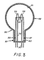
- Glow discharge lamp 50 includes a lamp envelope that has a bulbous region 52 and a neck region 53.
- the envelope contains mercury and a noble gas (e.g., neon) at a low pressure, such as 2 torr.
- a phosphor coating 51 is disposed on an inner surface of the envelope to emit visible light upon absorption of ultraviolet radiation that occurs when the lamp is excited.
- Cathode electrode 54 is in the form of an exciter coil having an emissive material disposed thereon.
- Lead-in wires 55 and 57 support the electrode 54 and electrically couple electrode 54 to taps T1 and T2 (FIG. 2).
- each of the anode electrodes 56, 58 is in the form of a wire ring and disposed so as to completely surround in a coaxial manner a respective portion of cathode electrode 54. Ring anodes 56, 58 lie in parallel planes which are perpendicular to cathode electrode 54. As illustrated in FIG.
- ring anodes 56, 58 are electrically isolated from cathode electrode 54 as well as from each other.
- Lead-in wires 72, 74 respectively couple ring electrodes 56, 58 and extend through wafer stem 60.
- Ring electrodes 56, 58 may each have a diameter of about 1 inch and may be separated a distance of about 1 centimeter from each other.
- the unique circuit operates a glow discharge lamp having two anodes in a DC regime from an AC line signal.
- the present invention provides a discharge which alternates between each anode every half-cycle of the line signal without additional diodes and switches.
- the discharge occurs in the same discharge space which eliminates the need for an inner tube or channel within the lamp.
- the circuit provides rapid lamp starting and continuous cathode heating.
Landscapes
- Circuit Arrangements For Discharge Lamps (AREA)
- Discharge Lamp (AREA)
Applications Claiming Priority (2)
| Application Number | Priority Date | Filing Date | Title |
|---|---|---|---|
| US07/289,951 US5177407A (en) | 1988-12-27 | 1988-12-27 | Glow discharge lamp having dual anodes and circuit for operating same |
| US289951 | 1988-12-27 |
Publications (2)
| Publication Number | Publication Date |
|---|---|
| EP0376173A2 true EP0376173A2 (fr) | 1990-07-04 |
| EP0376173A3 EP0376173A3 (fr) | 1992-03-04 |
Family
ID=23113886
Family Applications (1)
| Application Number | Title | Priority Date | Filing Date |
|---|---|---|---|
| EP19890123698 Withdrawn EP0376173A3 (fr) | 1988-12-27 | 1989-12-21 | Lampe à décharge de type lueur ayant deux anodes et circuit pour l'alimenter |
Country Status (4)
| Country | Link |
|---|---|
| US (1) | US5177407A (fr) |
| EP (1) | EP0376173A3 (fr) |
| JP (1) | JPH02270297A (fr) |
| CA (1) | CA2006282C (fr) |
Cited By (2)
| Publication number | Priority date | Publication date | Assignee | Title |
|---|---|---|---|---|
| EP0762807A3 (fr) * | 1995-09-08 | 1998-04-15 | Patent-Treuhand-Gesellschaft für elektrische Glühlampen mbH | Circuit pour alimenter des lampes à décharge à lueur |
| WO2001033606A1 (fr) * | 1999-11-02 | 2001-05-10 | Koninklijke Philips Electronics N.V. | Systeme d'eclairage |
Families Citing this family (3)
| Publication number | Priority date | Publication date | Assignee | Title |
|---|---|---|---|---|
| EP1747574A1 (fr) * | 2004-05-11 | 2007-01-31 | Koninklijke Philips Electronics N.V. | Lampe a decharge de vapeur de mercure basse pression et dispositif d'affichage |
| US20060175973A1 (en) * | 2005-02-07 | 2006-08-10 | Lisitsyn Igor V | Xenon lamp |
| US8487544B2 (en) | 2010-09-29 | 2013-07-16 | Osram Sylvania Inc. | Power splitter circuit for electrodeless lamp |
Family Cites Families (19)
| Publication number | Priority date | Publication date | Assignee | Title |
|---|---|---|---|---|
| GB308288A (en) * | 1927-12-16 | 1929-03-18 | Philips Nv | Improvements in or relating to circuit arrangements embodying discharge tubes |
| GB407918A (en) * | 1932-06-24 | 1934-03-29 | British Thomson Houston Co Ltd | Improvements in and relating to electric illuminating apparatus |
| US2265323A (en) * | 1932-07-13 | 1941-12-09 | Gen Electric | Gas and metal vapor discharge tube and means for preventing flicker therein |
| GB528248A (en) * | 1938-03-22 | 1940-10-25 | British Thomson Houston Co Ltd | Improvements relating to the starting of gaseous electric discharge devices such as lamps |
| US2259954A (en) * | 1938-11-30 | 1941-10-21 | Westinghouse Electric & Mfg Co | Lamp and operating circuit |
| US2356369A (en) * | 1941-12-08 | 1944-08-22 | Products Dev Inc | Gaseous discharge tube circuit |
| US2401998A (en) * | 1943-06-19 | 1946-06-11 | Sylvania Electric Prod | Electrial discharge device |
| US3500122A (en) * | 1964-10-20 | 1970-03-10 | Xerox Corp | Gas discharge ion source with multiple anode structure and a.c. supply means |
| US3635537A (en) * | 1969-12-29 | 1972-01-18 | California Inst Of Techn | Multiple anode arc lamp system |
| BE793068A (fr) * | 1971-12-22 | 1973-06-20 | Philips Nv | Dispositif d'amorcage et d'alimentation d'une lampe a decharge dans le gaz et/ou dans la vapeur |
| US3787751A (en) * | 1972-08-10 | 1974-01-22 | Thorn Electrical Ind Ltd | Ballast circuits for discharge lamps |
| DE2862125D1 (en) * | 1977-08-10 | 1983-01-20 | Hitachi Ltd | Low pressure metal vapour discharge lamp |
| US4172981A (en) * | 1978-06-15 | 1979-10-30 | Francis H. Harrington | Lighting system |
| US4288725A (en) * | 1979-11-26 | 1981-09-08 | Westinghouse Electric Corp. | Lightweight fluorescent lamp ballast |
| US4518897A (en) * | 1982-01-04 | 1985-05-21 | Gte Laboratories Incorporated | Twin anode beam mode fluorescent lamp |
| US4500812A (en) * | 1983-02-14 | 1985-02-19 | Gte Products Corporation | Electronic ballast circuit |
| US4751435A (en) * | 1984-12-13 | 1988-06-14 | Gte Laboratories Incorporated | Dual cathode beam mode fluorescent lamp with capacitive ballast |
| US4754194A (en) * | 1986-09-26 | 1988-06-28 | Wilson Feliciano | Flourescent light bulb |
| JPS63141252A (ja) * | 1986-12-02 | 1988-06-13 | Hitachi Ltd | 低圧放電灯 |
-
1988
- 1988-12-27 US US07/289,951 patent/US5177407A/en not_active Expired - Fee Related
-
1989
- 1989-12-21 EP EP19890123698 patent/EP0376173A3/fr not_active Withdrawn
- 1989-12-21 CA CA002006282A patent/CA2006282C/fr not_active Expired - Fee Related
- 1989-12-26 JP JP1335252A patent/JPH02270297A/ja active Pending
Cited By (3)
| Publication number | Priority date | Publication date | Assignee | Title |
|---|---|---|---|---|
| EP0762807A3 (fr) * | 1995-09-08 | 1998-04-15 | Patent-Treuhand-Gesellschaft für elektrische Glühlampen mbH | Circuit pour alimenter des lampes à décharge à lueur |
| WO2001033606A1 (fr) * | 1999-11-02 | 2001-05-10 | Koninklijke Philips Electronics N.V. | Systeme d'eclairage |
| US6541899B1 (en) | 1999-11-02 | 2003-04-01 | Koninklijke Philips Electronics N.V. | Discharged lamp with multiple electron emissive electrode bodies |
Also Published As
| Publication number | Publication date |
|---|---|
| US5177407A (en) | 1993-01-05 |
| JPH02270297A (ja) | 1990-11-05 |
| CA2006282C (fr) | 1994-02-01 |
| EP0376173A3 (fr) | 1992-03-04 |
| CA2006282A1 (fr) | 1990-06-27 |
Similar Documents
| Publication | Publication Date | Title |
|---|---|---|
| CA1178647A (fr) | Ballast leger pour lampes a fluorescence | |
| CA2032058C (fr) | Circuit de gradation de lampes a decharge luminescente sans production de stries | |
| EP0827184B1 (fr) | Lampe compacte fluorescente sans électrode de type "a-line" | |
| JPH07220880A (ja) | カソード加熱型ガス放電ランプの安定回路 | |
| US6236168B1 (en) | Ballast instant start circuit | |
| US6459204B1 (en) | Dual-element 3-way compact fluorescent lamp | |
| GB2102640A (en) | Circuit for starting and operating fluorescent lamps | |
| EP0072622A2 (fr) | Système économiseur d'énergie fournissant une commande de courant | |
| US2301671A (en) | Auxiliary equipment for luminescent tubes | |
| US5177407A (en) | Glow discharge lamp having dual anodes and circuit for operating same | |
| US4117377A (en) | Circuits for starting and operating ionized gas lamps | |
| US6118227A (en) | High frequency electronic drive circuits for fluorescent lamps | |
| US4952844A (en) | Electronic ballast circuit for discharge lamp | |
| US2337992A (en) | High power factor high intensity lamp circuit | |
| CA1118487A (fr) | Regulateur de puissance leger pour lampe fluorescente | |
| US4587462A (en) | Fluorescent light source with parallel DC discharges | |
| US5021714A (en) | Circuit for starting and operating fluorescent lamps | |
| US4654560A (en) | Three (3)-way lamp having a tungsten halogen inner envelope | |
| EP0415738B1 (fr) | Systèmes contenant des lampes à décharge | |
| US4494041A (en) | Incandescent ballast assembly | |
| JPH07272882A (ja) | 放電ランプ用安定化電源装置 | |
| GB2114385A (en) | Cathode phasing circuits for discharge | |
| EP0492722B1 (fr) | Lampe à décharge dans les gaz commandée par une grille | |
| MXPA01005529A (es) | Reactor de resonancia en paralelo, alimentado con corriente. | |
| KR920000482B1 (ko) | 발광장치 |
Legal Events
| Date | Code | Title | Description |
|---|---|---|---|
| PUAI | Public reference made under article 153(3) epc to a published international application that has entered the european phase |
Free format text: ORIGINAL CODE: 0009012 |
|
| 17P | Request for examination filed |
Effective date: 19900117 |
|
| AK | Designated contracting states |
Kind code of ref document: A2 Designated state(s): BE DE FR GB NL |
|
| PUAL | Search report despatched |
Free format text: ORIGINAL CODE: 0009013 |
|
| AK | Designated contracting states |
Kind code of ref document: A3 Designated state(s): BE DE FR GB NL |
|
| 17Q | First examination report despatched |
Effective date: 19930726 |
|
| STAA | Information on the status of an ep patent application or granted ep patent |
Free format text: STATUS: THE APPLICATION IS DEEMED TO BE WITHDRAWN |
|
| 18D | Application deemed to be withdrawn |
Effective date: 19931207 |