EP0376178B1 - Machine-outils à moteur de broche refroidi - Google Patents
Machine-outils à moteur de broche refroidi Download PDFInfo
- Publication number
- EP0376178B1 EP0376178B1 EP89123721A EP89123721A EP0376178B1 EP 0376178 B1 EP0376178 B1 EP 0376178B1 EP 89123721 A EP89123721 A EP 89123721A EP 89123721 A EP89123721 A EP 89123721A EP 0376178 B1 EP0376178 B1 EP 0376178B1
- Authority
- EP
- European Patent Office
- Prior art keywords
- machine tool
- spindle
- cooling
- stator
- axis
- Prior art date
- Legal status (The legal status is an assumption and is not a legal conclusion. Google has not performed a legal analysis and makes no representation as to the accuracy of the status listed.)
- Expired - Lifetime
Links
- 238000001816 cooling Methods 0.000 title claims description 86
- 239000002826 coolant Substances 0.000 claims description 28
- 238000003475 lamination Methods 0.000 description 14
- 239000007788 liquid Substances 0.000 description 2
- 238000004873 anchoring Methods 0.000 description 1
- 238000010276 construction Methods 0.000 description 1
- 239000000110 cooling liquid Substances 0.000 description 1
- 230000006735 deficit Effects 0.000 description 1
- 230000000694 effects Effects 0.000 description 1
- 230000002349 favourable effect Effects 0.000 description 1
- 239000003595 mist Substances 0.000 description 1
- 239000002245 particle Substances 0.000 description 1
- 230000000149 penetrating effect Effects 0.000 description 1
- 230000035515 penetration Effects 0.000 description 1
- 230000002093 peripheral effect Effects 0.000 description 1
- 230000006641 stabilisation Effects 0.000 description 1
- 238000011105 stabilization Methods 0.000 description 1
- 238000005496 tempering Methods 0.000 description 1
- 230000007704 transition Effects 0.000 description 1
Images


Classifications
-
- B—PERFORMING OPERATIONS; TRANSPORTING
- B23—MACHINE TOOLS; METAL-WORKING NOT OTHERWISE PROVIDED FOR
- B23Q—DETAILS, COMPONENTS, OR ACCESSORIES FOR MACHINE TOOLS, e.g. ARRANGEMENTS FOR COPYING OR CONTROLLING; MACHINE TOOLS IN GENERAL CHARACTERISED BY THE CONSTRUCTION OF PARTICULAR DETAILS OR COMPONENTS; COMBINATIONS OR ASSOCIATIONS OF METAL-WORKING MACHINES, NOT DIRECTED TO A PARTICULAR RESULT
- B23Q11/00—Accessories fitted to machine tools for keeping tools or parts of the machine in good working condition or for cooling work; Safety devices specially combined with or arranged in, or specially adapted for use in connection with, machine tools
- B23Q11/12—Arrangements for cooling or lubricating parts of the machine
- B23Q11/126—Arrangements for cooling or lubricating parts of the machine for cooling only
- B23Q11/127—Arrangements for cooling or lubricating parts of the machine for cooling only for cooling motors or spindles
-
- B—PERFORMING OPERATIONS; TRANSPORTING
- B23—MACHINE TOOLS; METAL-WORKING NOT OTHERWISE PROVIDED FOR
- B23B—TURNING; BORING
- B23B9/00—Automatic or semi-automatic turning-machines with a plurality of working-spindles, e.g. automatic multiple-spindle machines with spindles arranged in a drum carrier able to be moved into predetermined positions; Equipment therefor
- B23B9/005—Spindle carriers: constructional details, drives for the spindles, or the like
-
- H—ELECTRICITY
- H02—GENERATION; CONVERSION OR DISTRIBUTION OF ELECTRIC POWER
- H02K—DYNAMO-ELECTRIC MACHINES
- H02K1/00—Details of the magnetic circuit
- H02K1/06—Details of the magnetic circuit characterised by the shape, form or construction
- H02K1/12—Stationary parts of the magnetic circuit
- H02K1/20—Stationary parts of the magnetic circuit with channels or ducts for flow of cooling medium
-
- H—ELECTRICITY
- H02—GENERATION; CONVERSION OR DISTRIBUTION OF ELECTRIC POWER
- H02K—DYNAMO-ELECTRIC MACHINES
- H02K9/00—Arrangements for cooling or ventilating
- H02K9/10—Arrangements for cooling or ventilating by gaseous cooling medium flowing in closed circuit, a part of which is external to the machine casing
- H02K9/12—Arrangements for cooling or ventilating by gaseous cooling medium flowing in closed circuit, a part of which is external to the machine casing wherein the cooling medium circulates freely within the casing
-
- Y—GENERAL TAGGING OF NEW TECHNOLOGICAL DEVELOPMENTS; GENERAL TAGGING OF CROSS-SECTIONAL TECHNOLOGIES SPANNING OVER SEVERAL SECTIONS OF THE IPC; TECHNICAL SUBJECTS COVERED BY FORMER USPC CROSS-REFERENCE ART COLLECTIONS [XRACs] AND DIGESTS
- Y10—TECHNICAL SUBJECTS COVERED BY FORMER USPC
- Y10T—TECHNICAL SUBJECTS COVERED BY FORMER US CLASSIFICATION
- Y10T82/00—Turning
- Y10T82/25—Lathe
- Y10T82/2524—Multiple
-
- Y—GENERAL TAGGING OF NEW TECHNOLOGICAL DEVELOPMENTS; GENERAL TAGGING OF CROSS-SECTIONAL TECHNOLOGIES SPANNING OVER SEVERAL SECTIONS OF THE IPC; TECHNICAL SUBJECTS COVERED BY FORMER USPC CROSS-REFERENCE ART COLLECTIONS [XRACs] AND DIGESTS
- Y10—TECHNICAL SUBJECTS COVERED BY FORMER USPC
- Y10T—TECHNICAL SUBJECTS COVERED BY FORMER US CLASSIFICATION
- Y10T82/00—Turning
- Y10T82/25—Lathe
- Y10T82/2552—Headstock
- Y10T82/2562—Spindle and bearings
Definitions
- the invention relates to a machine tool with a machine frame, with a spindle drum rotatably mounted in the machine frame, with a plurality of motor spindles arranged in the spindle drum about an axis thereof, comprising a main motor integrated in a work spindle coaxial with a spindle axis, which in turn has a rotor and a stator .
- Such a machine tool is known from DE-OS 34 28 861.
- the motor spindles are ordinary motor spindles without cooling.
- asynchronous three-phase motors are used as the main motors, which can withstand very high loads and deliver constant power over a wide control range.
- the temperature stabilization of the main motor is particularly critical, since the main motor itself is part of a high-precision work spindle, so that strong temperature fluctuations would cause inaccuracies due to deformation of the spindle housing. For this reason, sufficient external cooling must be provided for all motor spindles, which always dissipates the heat loss regardless of the working point of the motor and keeps the motor temperature below the desired limits.
- the three-phase motors are cooled only in the area of their casing outer surface, an air stream being passed over the casing in the axial direction.
- the heat from the stator is dissipated via heat conduction to the housing.
- the housing cooling surfaces are enlarged, for example by ribs or a double jacket.
- this type of cooling is not sufficient for precise motor spindles.
- the invention is therefore based on the object of improving a machine tool of the generic type in such a way that simple and effective cooling of the main motors of the motor spindle is possible.
- a cooling device which supplies gaseous cooling medium to the cooling device of the main motor is provided in that the stator is constructed from stator laminations which in turn form the cooling surfaces so that the gaseous cooling medium immediately along the Cooling surfaces of the stator plates is guided that the cooling surfaces in the radial direction of the axis of the spindle drum form cooling channels that the cooling device one to an outer peripheral side of the Has spindle drum guided channel and a central channel surrounded by the main motors and that the channels of the gaseous cooling medium on the one hand to the spindle drum and on the other hand lead away from the same.
- stator laminations themselves form the cooling surfaces and that a much more effective cooling of the main motor is possible than in all the cases in which an additional heat transport from the stator to additional cooling fins of a cooling jacket takes place.
- the cooling fins form cooling channels running in the radial direction of the spindle drum, since then the gaseous cooling medium can flow in the radial direction to the axis of the spindle drum, which is particularly advantageous if there is an impairment of the front and Backs of the spindles is avoided by means of guiding the gaseous cooling medium.
- stator plates In particular for enlarging the cooling surfaces, it has proven to be particularly expedient for the stator plates to have a non-uniform radial extension and thus to form cooling surfaces.
- stator sheets themselves any shapes which bring about an enlargement of the cooling surfaces, the cooling surfaces being able to arise both through channels in the entirety of the stator sheets or through surfaces formed by the stator sheets.
- the solution according to the invention can be achieved in a particularly simple manner in that different stator sheets have a different radial extension.
- cooling surfaces on the stator should be.
- the cooling surfaces could also be formed by channels in the entirety of the stator sheets.
- cooling can be achieved in a particularly simple manner in that the stator sheets form a cooling surface protruding on an outside of the stator facing away from the motor.
- stator plates form cooling fins extending in the radial direction to the spindle axis.
- cooling fins can be created quite simply in that they are formed by different radial extensions of successive stator laminations, ie that the stator laminations successively either have a larger one or have a smaller radial extension and thus enlarge the cooling surface on the outside of the stator.
- stator sheets alternately have a different diameter; so that a stator sheet with a large diameter follows a stator sheet with a small diameter.
- the cooling fins are formed thereby that successive stator laminations form packages with a different radial extension relative to one another. This means that several stator laminations have the same radial extension, form a package, which is followed by a package of stator laminations with a different radial extension.
- the individual packages of stator laminations can thus form the most varied forms of cooling fins.
- any conceivable course of cooling fins would be possible relative to the spindle axis.
- cooling fins extend in planes extending transversely to the spindle axis, since then, for example, the same packages of stator laminations with alternating diameters can be arranged in succession.
- cooling fins are only short pieces or extend over longer areas on the outside of the stator.
- it has proven to be expedient if there are at least partially circumferential cooling channels between the cooling fins, so that the gaseous cooling medium does not have to flow on all sides, but is sufficient to apply the gaseous cooling medium to the stator at certain points, which can then flow around and cool it in the cooling channels which partially circulate around the stator.
- the cooling channels can run in all possible directions. For example, it would be conceivable for the cooling channels to wind around the stator in a helical or zigzag fashion.
- cooling channels lie in planes running transversely to the spindle axis, since then a cross-flow to the stator is possible for cooling the same, which has proven to be extremely favorable when the motor spindle is used in machine tools.
- a particularly preferred embodiment of the machine tool according to the invention provides that the cooling device is designed such that the cooling medium in the main motor is under excess pressure. This has the advantage that the main motor as a whole is protected from dirt and, for example, mist from the coolant or coolant itself.
- spindle bearing facing a working space is exposed to the cooling medium under excess pressure is acted upon.
- This spindle bearing is the most susceptible of the motor spindle, because due to the fact that it is essentially close to the work area, it is very exposed to the ingress of fog and the coolant or coolant itself or other dirt particles and can therefore easily corrode or otherwise be damaged . For this reason, it is particularly advantageous if this spindle bearing can be protected by the fact that it is constantly subjected to the pressurized cooling medium, which counteracts the ingress of dirt and coolant.
- the cooling device has a cooler for the cooling medium supplied to the main motor, so that this cooling medium is pre-cooled to the desired temperature before it enters the respective main motor or the respective main motors can and on the other hand, the cooling surfaces of the main motors can be kept smaller, which in turn allows the advantage of a more compact design of the main motor when installed in the machine tool and thus brings great structural advantages, especially in machine tools with several main motors in a spindle drum.
- the cooling device comprises a blower so that a forced air flow is achieved, the blower advantageously being arranged in the machine frame and thus being able to be arranged and operated separately from the main motors and thus being able to be carried out independently of the speed of the main motors Tempering is possible.
- All the main motors can be cooled together particularly easily by virtue of the fact that the channel leading to the outer circumferential side of the spindle drum encloses the outer circumferential side of the same and thus supplies all the main motors with cooling medium.
- the central channel extends in the direction of the axis of the spindle drum.
- a preferred embodiment provides that the stators of the main motors of the motor spindles abut each other with their cooling fins and are thereby already supported against one another, so that there are substantially improved possibilities for anchoring the stators in the spindle drum.
- cooling fins have a radial boundary surface of circular segments of corresponding outer contour, the size of the circular segment being determined by the number of spindles, that is to say either 1/6 or 1/8 circular segment with 6 or 8 motor spindles.
- cooling fins are supported on support strips of a cage serving as a spindle drum frame.
- An embodiment of the solution according to the invention can be implemented particularly advantageously in terms of design when the work spindle carries the rotor and thus in particular supports it rotatably relative to the stator, although a very efficient temperature control of the main motor is then necessary for the reasons mentioned at the beginning.
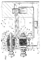
- a multi-spindle automatic lathe designated as a whole as 10 in FIG. 1 as an example of a machine tool according to the invention comprises a frame designated as a whole as 12 with a spindle housing 14 and a control housing 16, between which there is a work space designated as a whole as 18.
- a spindle drum Arranged in the spindle housing 14 is a spindle drum, designated as a whole as 20, which faces the working space 18 with a front end face 22.
- the spindle drum 20 comprises a plurality of, preferably 6 or 8, spindles 24, the front ends 26 of which also protrude beyond the front end side 22 and face the working space 18.
- spindles 24 are, as can be seen in particular from FIG. 2, designed as motor spindles, that is to say that a respective main motor 28 is integrated in the spindle 24, which has a rotor 32 which is fixedly seated on a spindle tube 30 and rotates therewith, and a fixed rotor in a frame 34 of the spindle drum 20 seated stator 36 comprises.
- the spindle tube 30 is in turn held in the frame 34 of the spindle drums 20 by means of a front bearing 38 and a rear bearing 40, the frame 34 in turn being rotatable about an axis 42 of the spindle drum 20, which in turn runs parallel to the spindle axes 44 of the spindles 24 .
- the rotatable mounting of the frame 34 takes place via cylindrical surface surfaces 46 of the spindle drum 20 which are coaxial with the axis 42 and which are supported in recesses 48 of the spindle housing 14 which are coaxial with the axis 42.
- a supply pipe 50 which is coaxial with the axis 42, is held on the frame 34 in a rotationally fixed manner, which projects beyond the end face 22 of the spindle drum 20, passes through the working space 18 and extends into the control housing 16. All supply and control lines for the main motors 28, such as power supply lines, are guided via this supply pipe 50.
- the rotor 32 is composed of a plurality of rotor plates 52 lying one behind the other built up.
- a small air gap 58 remains between an outer circumference 54 of the rotor 32 and an inner surface 56 of the stator 36 facing it.
- the stator 36 in turn is likewise constructed from a multiplicity of stator laminations 60 which are located one behind the other in the direction of the spindle axis 44 and which are aligned approximately at right angles to the spindle axis 44 and extend around the rotor 32.
- stator laminations 60 lying one behind the other are combined to form first packets 62 and second packets 64, the packets 62 and 64 following one another and alternating in the direction of the spindle axis 44.
- the first package 62 comprises stator laminations 60 which extend from the inner surface 56 of the stator 36 in the radial direction to the spindle axis 44 and together with their outer edges 66 form a cylindrical outer surface 68 which is coaxial with the spindle axis 44.
- the second packets 64 also extend in the radial direction from the inner surface 56 of the stator 36, but beyond the outer surfaces 68 of the first packs 62 and, with their respective outer edges 70, form an outer contour 72 which is adapted to the special conditions of the spindle drum 20.
- This outer contour 72 fits once with one with respect to the axis 42 of the Spindle drum 20 radially outer jacket piece 74 on the cylinder jacket surfaces 46 so that the outer contour 72 of the second packets 64 does not protrude beyond the spindle drum 20.
- Supporting areas 76 of the outer contour 72 adjoin on both sides of the jacket piece 74, with which the second packs 64 abut on essentially triangular support strips 78 of the frame 34 which extend parallel to the axis 42.
- These support strips 78 each lie between two main motors 28 and, overall, form a cage carrying the main motors 28 in the region of a periphery of the spindle drum 20.
- the outer contour 72 with radial areas 80 runs in the radial direction to the axis 42 inwards up to an edge area 82 which connects the two radial areas 80 of the outer contour 72 and in turn delimits a central channel 84.
- the edge area 82 is preferably designed as a segment of a lateral surface of a cylinder coaxial with the axis 42.
- the second packets 64 of adjacent main motors abut one another and are therefore supported on one another.
- the outer contour 72 of the second packets 64 of the stator laminations 60 serves to support the stators 36 of the individual main motors on the one hand on the cage of the frame 34 of the spindle drum 20 formed by the support strips 78 and on the other hand to support them in the radial areas 80 to support each other, so that the total of six stators 36 shown in FIG. 4 within the spindle drum 20 form a compact and stable unit.
- the cooling channels 88 run from the jacket region 64 in the radial direction with respect to the axis 42 inwards to the center channel 84 in planes perpendicular to the axis 42 around the outer surfaces 68 of the first packets 62 and thus also around the entire rotor enclosed by the stator 36 32.
- the spindle housing 14 with its section 90 that extends over the casing regions 74 is set back relative to the casing regions 74 of the outer contours 72 of the second packets 64, so that a gap 92 is formed between the casing regions 74 and the sections 90, which revolves around the spindle drum 20.
- This gap 92 opens into a supply air duct 94, which from below is arranged by a fan 96 arranged in a lower region of the frame 12 Spindle housing 14 is guided.
- a cooler 98 is provided therein for the air guided by the blower 96, so that the air blown into the gap 92 can be cooled.
- This cooled air then flows in the gap 92 around the spindle drum 20 and is guided in the cooling channels 88 in the radial direction to the axis 42 of the spindle drum 20 inwards to the central channel 84, from which - as can be seen from FIG. 2 - through an opening 100 of the supply pipe 50 can enter the latter and is discharged along the supply pipe 50 in the direction of the control housing 16.
- the air can preferably be collected at an end 102 of the supply pipe 50 located in the control housing 16 and fed to the blower 96, so that there is an overall circuit for cooling air in which the stators 36 of all the main motors 28 are effectively cooled.
- a cooling of the main motors 28 according to the invention is preferably carried out with overpressure of the gaseous medium, so that there is an overpressure in each spindle 24, which advantageously prevents dirt and coolant from penetrating into the bearings 38, 40, in particular into the front bearing 38 facing the working space 18 counteracts.
Landscapes
- Engineering & Computer Science (AREA)
- Mechanical Engineering (AREA)
- Power Engineering (AREA)
- Motor Or Generator Cooling System (AREA)
- Turning (AREA)
Claims (20)
- Machine-outil comportant un bâti (12), comprenant un tambour porte-broches (20) monté rotatif dans le bâti (12), plusieurs broches motrices (24) disposées dans le tambour (20) porte-broches et dont chacune comprend un moteur principal intégré dans une broche de travail (24) coaxialement à l'axe de la broche et comprenant de son côté un rotor (32) et un stator (36), caractérisée en ce qu'un dispositif de refroidissement est prévu pour diriger un fluide gazeux de refroidissement sur des surfaces de refroidissement (68, 86) du moteur principal (28), en ce que le stator (36) est constitué de tôles statoriques (60) qui forment de leur côté une surface de refroidissement (68, 86), en ce que le fluide gazeux de refroidissement est dirigé directement le long des surfaces de refroidissement (68, 86) des tôles statoriques (60), en ce que les surfaces de refroidissement (86) forment des canaux de refroidissement (88) orientés en direction radiale par rapport à l'axe (42) du tambour (20) porte-broches, en ce que le dispositif de refroidissement comprend un canal (92) orienté vers un côté circonférenciel extérieur du tambour (20) porte-broches et un canal central (84) entouré par les moteurs principaux (28) et en ce que les canaux (84, 92) d'une part dirigent le fluide gazeux de refroidissement sur le tambour (20) porte-broches et d'autre part l'en évacuent.
- Machine-outil selon la revendication 1, caractérisée en ce que les tôles statoriques (60) ont des étendues radiales différentes par rapport à l'axe (44) des broches et forment ainsi des surfaces de refroidissement (68, 86).
- Machine-outil selon la revendication 2, caractérisée en ce que des tôles statoriques différentes (60) ont des étendues radiales différentes.
- Machine-outil selon l'une des revendciations précédentes, caractérisée en ce que les tôles statoriques (60) forment des surfaces de refroidissement (68, 86) disposées sur un côté extérieur du stator (36) qui est tourné à l'opposé du rotor (32).
- Machine-outil selon l'une des revendications 2 à 4, caractérisée en ce que les tôles statoriques (60) forment des ailettes de refroidissement (86) orientées en direction radiale sur l'axe (44) des broches.
- Machine-outil selon la revendication 5, caractérisée en ce que les ailettes de refroidissement (86) sont formées par des étendues radiales différentes des tôles statoriques successives (60).
- Machine-outil selon la revendication 6, caractérisée en ce que les ailettes de refroidissement (86) sont formées par le fait que des tôles statoriques successives (60) forment des paquets (62, 64) ayant des étendues radiales différentes les uns par rapport aux autres.
- Machine-outil selon l'une des revendications 5 à 7, caractérisée en ce que les ailettes de refroidissement (86) sont orientées dans des plans perpendiculaires à l'axe (44) des broches.
- Machine-outil selon l'une des revendications 5 à 8, caractérisée en ce que des canaux de refroidissement (88) passant au moins partiellement autour du stator (36) sont situés entre les ailettes de refroidissement (86).
- Machine-outil selon l'une des revendications précédentes, caractérisée en ce que le dispositif de refroidissement est réalisé de manière que le fluide de refroidissement soit en dépression dans le moteur principal (28).
- Machine-outil selon la revendication 10, caractérisée en ce qu'un palier de broche (38) tourné vers un espace de travail (18) est balayé par le fluide de refroidissement en dépression.
- Machine-outil selon la revendication 11, caractérisée en ce que les paliers (38, 40) des broches (24) sont balayés par le fluide de refroidissement en dépression.
- Machine-outil selon l'une des revendications précédentes, caractérisée en ce que le dispositif de refroidissement comprend un radiateur (98) pour le fluide de refroidissement dirigé sur le moteur principal (28).
- Machine-outil selon l'une des revendications précédentes, caractérisée en ce que le dispositif de refroidissement comprend un ventilateur (96).
- Machine-outil selon la revendication 14, caractérisée en ce que le ventilateur (96) est disposé dans le bâti (12) de la machine.
- Machine-outil selon l'une des revendications précédentes, caractérisée en ce que le canal (92) passant sur le côté circonférentiel extérieur du tambour porte-broches (20) entoure le côté circonférentiel extérieur de ce dernier.
- Machine-outil selon l'une des revendications précédentes, caractérisée en ce que le canal central (84) est orienté dans la direction de l'axe (42) du tambour porte-broches (20).
- Machine-outil selon l'une des revendications précédentes, caractérisée en ce que les ailettes de refroidissement (86) servent également à l'appui des stators (36) dans le tambour porte-broches (20).
- Machine-outil selon l'une des revendications précédentes, caractérisée en ce que les ailettes de refroidissement (86) des stators (36) des moteurs principaux (28) des broches motrices (24) sont appliquées par zones les unes contre les autres.
- Machine-outil selon l'une des revendications précédentes, caractérisée en ce que la broche de travail (24) supporte le rotor (32).
Applications Claiming Priority (2)
| Application Number | Priority Date | Filing Date | Title |
|---|---|---|---|
| DE3844337 | 1988-12-30 | ||
| DE3844337A DE3844337A1 (de) | 1988-12-30 | 1988-12-30 | Werkzeugmaschine mit gekuehlter motorspindel |
Publications (2)
| Publication Number | Publication Date |
|---|---|
| EP0376178A1 EP0376178A1 (fr) | 1990-07-04 |
| EP0376178B1 true EP0376178B1 (fr) | 1994-03-02 |
Family
ID=6370537
Family Applications (1)
| Application Number | Title | Priority Date | Filing Date |
|---|---|---|---|
| EP89123721A Expired - Lifetime EP0376178B1 (fr) | 1988-12-30 | 1989-12-22 | Machine-outils à moteur de broche refroidi |
Country Status (4)
| Country | Link |
|---|---|
| US (1) | US5062330A (fr) |
| EP (1) | EP0376178B1 (fr) |
| JP (1) | JP2899334B2 (fr) |
| DE (2) | DE3844337A1 (fr) |
Cited By (1)
| Publication number | Priority date | Publication date | Assignee | Title |
|---|---|---|---|---|
| TWI406723B (fr) * | 2010-05-12 | 2013-09-01 |
Families Citing this family (35)
| Publication number | Priority date | Publication date | Assignee | Title |
|---|---|---|---|---|
| DE4214667C1 (en) * | 1992-05-02 | 1993-09-09 | Schleifmaschinenwerk Gmbh Chemnitz, O-9034 Chemnitz, De | Cooling unit facility for electric motor drive of machine tool - includes cooling flange with heat insulating flange fitted between machine tool housing, and centring set of motor housing flange secured by fixing elements |
| DE4311431C2 (de) * | 1993-04-07 | 1995-07-13 | Index Werke Kg Hahn & Tessky | Motorspindel für eine Werkzeugmaschine |
| US5491371A (en) * | 1993-12-13 | 1996-02-13 | Able Corporation | Electrical machinery laminations cooling |
| WO1995021723A1 (fr) * | 1994-02-15 | 1995-08-17 | Seiko Seiki Kabushiki Kaisha | Machine-outil a deux broches reversibles |
| DE4431814A1 (de) * | 1994-09-07 | 1996-03-14 | Index Werke Kg Hahn & Tessky | Automatische Werkstoffstangen-Zuführeinrichtung für Werkzeugmaschinen, insbesondere Drehautomaten |
| DE19504369A1 (de) * | 1995-02-10 | 1996-08-14 | Index Werke Kg Hahn & Tessky | Mehrspindelwerkzeugmaschine |
| DE29507871U1 (de) * | 1995-05-12 | 1995-07-27 | Hermann Pfauter GmbH & Co., 71636 Ludwigsburg | Wälzfräsmaschine |
| US5676030A (en) * | 1995-08-14 | 1997-10-14 | Crudgington Machine Tools, Inc. | Multi-spindle CNC lathe |
| DE19622475A1 (de) * | 1996-06-05 | 1997-12-11 | Index Werke Kg Hahn & Tessky | Werkzeugmaschine |
| FR2758488B1 (fr) * | 1997-01-20 | 1999-02-12 | Jean Michel Delacou | Dispositif d'usinage par enlevement de copeaux, a bloc massif et colonne coulissante et machine incorporant ce dispositif |
| DE19835954A1 (de) * | 1998-08-08 | 2000-02-17 | Index Werke Kg Hahn & Tessky | Werkzeugmaschine |
| US5982071A (en) * | 1998-08-13 | 1999-11-09 | Able Corporation | Cooling of electrical machinery |
| DE10133653A1 (de) * | 2001-07-11 | 2003-01-30 | Siemens Ag | Anordnung elektrischer Maschinen |
| KR20030069663A (ko) * | 2002-02-22 | 2003-08-27 | 주식회사 광진기계 | 팬을 구비한 스핀들 모터구조 |
| US6848348B2 (en) * | 2002-03-15 | 2005-02-01 | Juei-Seng Liao | Wood lathe with a cooling fan |
| FR2838253B1 (fr) * | 2002-04-03 | 2005-09-23 | Leroy Somer Moteurs | Machine electrique tournante a ventilation forcee |
| DE102004004935B4 (de) * | 2004-01-31 | 2006-07-13 | Kostakis Andreu | Werkzeugmaschine |
| DE102004007484A1 (de) * | 2004-02-13 | 2005-09-08 | Siemens Ag | Kühlsystem |
| DE102004022301A1 (de) * | 2004-05-04 | 2005-12-01 | E + B Elektromaschinen + Beratung R. Meyer | Werkzeugmaschinen-Elektrospindel |
| US7185573B1 (en) * | 2005-02-18 | 2007-03-06 | Hayes Lemmerz International, Inc. | Vacuum wheel chuck |
| DE102006009786A1 (de) * | 2006-03-01 | 2007-09-06 | Emag Holding Gmbh | Antrieb für eine Schleifspindel |
| DE502007000464D1 (de) * | 2006-07-18 | 2009-04-09 | Kessler Franz Gmbh | Spindeleinheit zum Einbau in eine Werkzeugmaschine |
| DE102010002804A1 (de) * | 2010-03-12 | 2011-09-15 | Index-Werke Gmbh & Co. Kg Hahn & Tessky | Mehrspindeldrehmaschine |
| EP2380699B1 (fr) * | 2010-04-26 | 2013-03-20 | Tornos SA | Indexage d'un barillet d'un tour multibroches |
| CN102554279A (zh) * | 2010-12-16 | 2012-07-11 | 江苏华雕机械有限公司 | 组合式的多电主轴单元 |
| US9991759B2 (en) * | 2014-03-06 | 2018-06-05 | Honeywell International Inc. | Multi-directional air cooling of a motor using radially mounted fan and axial/circumferential cooling fins |
| EP2949422B1 (fr) | 2014-05-27 | 2017-05-17 | Step-Tec AG | Dispositif de refroidissement de composants de machine au moyen de PCM |
| CN105108548A (zh) * | 2015-09-09 | 2015-12-02 | 江苏华雕机械有限公司 | 一种复合雕铣气动手动双用换刀定向风冷电主轴 |
| US10197149B2 (en) * | 2016-03-23 | 2019-02-05 | Kawasaki Jukogyo Kabushiki Kaisha | V-belt type continuously variable transmission |
| JP6948915B2 (ja) * | 2017-10-31 | 2021-10-13 | シチズン時計株式会社 | 工作機械 |
| CN108161035A (zh) * | 2018-03-06 | 2018-06-15 | 衢州学院 | 分形流道散热结构及电主轴 |
| CN111151771A (zh) * | 2020-01-21 | 2020-05-15 | 广州市昊志机电股份有限公司 | 一种采用抱夹冷却的电主轴 |
| CN112296743A (zh) * | 2020-10-22 | 2021-02-02 | 福建省庆川数控机械有限公司 | 一种节能环保型数控机床 |
| USD1048643S1 (en) * | 2022-09-23 | 2024-10-22 | Edward Joseph Della Monica | Motorcycle engine urn |
| CZ310194B6 (cs) * | 2023-07-25 | 2024-11-06 | David Ing. Imrich | Vícevřetenový obráběcí stroj |
Family Cites Families (20)
| Publication number | Priority date | Publication date | Assignee | Title |
|---|---|---|---|---|
| GB387622A (en) * | 1931-05-19 | 1933-02-09 | Paul Ehrmann | Improvements relating to electric machines with laminated masses |
| DE583022C (de) * | 1931-10-01 | 1933-08-26 | Siemens Schuckertwerke Akt Ges | Waermeschutz fuer Lager |
| US2379147A (en) * | 1942-06-20 | 1945-06-26 | Leblond Mach Tool Co R K | Automatic lathe |
| FR1517088A (fr) * | 1967-02-03 | 1968-03-15 | Drouard Moteurs | Perfectionnements aux machines électriques |
| DE1811260B1 (de) * | 1968-11-27 | 1971-08-05 | Witalij Arsenjewiz Obuchow | Staender einer elektrischen maschine mit durch lueftungs kanaele axial voneinander getrennten blechpaketen |
| SU616458A1 (ru) * | 1975-02-28 | 1978-07-25 | Предприятие П/Я А-7054 | Подшипниковый узел |
| FR2312875A1 (fr) * | 1975-05-28 | 1976-12-24 | Guimbal Jean | Alternateur sans enroulement rotorique |
| DE2711238C3 (de) * | 1977-03-15 | 1980-12-18 | K.K. Meidensha, Tokio | Frässpindelanordnung |
| DE2928027C2 (de) * | 1979-07-11 | 1981-10-01 | Siemens AG, 1000 Berlin und 8000 München | Elektrische Maschine mit einem auf der Maschinenwelle befestigten Lüfter |
| DE3007917A1 (de) * | 1980-03-01 | 1981-09-17 | Heinrich Baumüller, Fabrik für Elektrotechnik GmbH, 8500 Nürnberg | Vorrichtung zum abfuehren der verlustwaerme einer geschlossenen elektrischen maschine |
| DE3274074D1 (en) * | 1982-01-08 | 1986-12-11 | Fanuc Ltd | A spindle head unit |
| JPS58201559A (ja) * | 1982-05-17 | 1983-11-24 | Fanuc Ltd | 主軸台の断熱装置 |
| US4514652A (en) * | 1983-07-13 | 1985-04-30 | Sundstrand Corporation | Liquid cooled high speed synchronous machine |
| DE3428861A1 (de) * | 1983-08-06 | 1985-02-14 | Index-Werke Kg Hahn & Tessky, 7300 Esslingen | Mehrspindel-drehautomat |
| US4665781A (en) * | 1985-02-25 | 1987-05-19 | Hofer Industries Inc. | Multi-spindle chucking machine |
| US4806810A (en) * | 1987-03-16 | 1989-02-21 | Sundstrand Corporation | Fastener sealing system for fasteners exposed to high ambient temperatures |
| DE3724186A1 (de) * | 1987-07-17 | 1989-01-26 | Siemens Ag | Elektrische maschine mit geschlossenem kuehlkreislauf |
| JPH01228751A (ja) * | 1988-03-09 | 1989-09-12 | Fanuc Ltd | 2つの主軸を有する工作機械 |
| DE8806657U1 (de) * | 1988-05-20 | 1988-07-07 | Gerhard Berger GmbH & Co KG Fabrik elektrischer Geräte, 7630 Lahr | Elektromotor |
| JP5119192B2 (ja) | 2009-03-31 | 2013-01-16 | 富士フイルム株式会社 | 光学式位置検出器及び光学装置 |
-
1988
- 1988-12-30 DE DE3844337A patent/DE3844337A1/de active Granted
-
1989
- 1989-12-22 DE DE89123721T patent/DE58907104D1/de not_active Expired - Lifetime
- 1989-12-22 EP EP89123721A patent/EP0376178B1/fr not_active Expired - Lifetime
- 1989-12-27 US US07/457,258 patent/US5062330A/en not_active Expired - Lifetime
- 1989-12-28 JP JP1338856A patent/JP2899334B2/ja not_active Expired - Fee Related
Cited By (1)
| Publication number | Priority date | Publication date | Assignee | Title |
|---|---|---|---|---|
| TWI406723B (fr) * | 2010-05-12 | 2013-09-01 |
Also Published As
| Publication number | Publication date |
|---|---|
| JPH02269435A (ja) | 1990-11-02 |
| DE3844337C2 (fr) | 1991-11-14 |
| DE3844337A1 (de) | 1990-07-05 |
| EP0376178A1 (fr) | 1990-07-04 |
| JP2899334B2 (ja) | 1999-06-02 |
| US5062330A (en) | 1991-11-05 |
| DE58907104D1 (de) | 1994-04-07 |
Similar Documents
| Publication | Publication Date | Title |
|---|---|---|
| EP0376178B1 (fr) | Machine-outils à moteur de broche refroidi | |
| EP2973951B1 (fr) | Moteur électrique présentant un refroidissement amélioré de la tête de bobine | |
| EP0623988B1 (fr) | Machine électrique | |
| EP0854559A1 (fr) | Rotor d'un turbogenérateur avec refroidissement direct à gaz | |
| DE2724421A1 (de) | Kuehlanordnung fuer rotorwickelkoepfe von dynamoelektrischen maschinen | |
| DE3490363T1 (de) | Umlaufende elektrische Maschine | |
| DE3434081A1 (de) | Umlaufende elektrische maschine | |
| AT518592B1 (de) | Wasserkraftgenerator und verfahren zu dessen herstellung und betrieb | |
| EP3584910B1 (fr) | Machine électrique à dissipation de la chaleur perdue améliorée | |
| DE102019112739A1 (de) | Elektrische Antriebseinheit für ein Kraftfahrzeug | |
| DE19919040C2 (de) | Synchronmaschine oder Asychronmaschine für große Windenergieanlagen | |
| EP1153467A1 (fr) | Machine electrique | |
| DE102021212153B4 (de) | Elektrische Maschine | |
| EP0008631A1 (fr) | Fraise composée | |
| DE112015005167T5 (de) | Wälzlager | |
| EP3020625A1 (fr) | Entraînement de nacelle électrique | |
| DE102018130516A1 (de) | Rotorwelle | |
| DE102022001674B4 (de) | Axialflussmaschine für ein Kraftfahrzeug, insbesondere für einen Kraftwagen | |
| EP4331095B1 (fr) | Machine électrique | |
| EP3023194B1 (fr) | Tour multibroche | |
| DE2107535C3 (de) | Rotor für eine elektrische Maschine mit einer supraleitenden Wicklung | |
| DE69202702T2 (de) | Läufer für einen kurzgeschlossenen wechselstrommotor. | |
| DE102021132595B4 (de) | Elektrisches Antriebssystem mit zwei Antriebsmaschinen und gehäuseseitiger Statorverschraubung | |
| EP1122865B1 (fr) | Agencement de machine électrique tournante avec machine électrique tournante et dispositif de refroidissement | |
| EP1032113A1 (fr) | Dispositif de refroidissement pour une machine électrique, notamment pour une machine à champ tournant |
Legal Events
| Date | Code | Title | Description |
|---|---|---|---|
| PUAI | Public reference made under article 153(3) epc to a published international application that has entered the european phase |
Free format text: ORIGINAL CODE: 0009012 |
|
| AK | Designated contracting states |
Kind code of ref document: A1 Designated state(s): CH DE ES FR GB IT LI |
|
| 17P | Request for examination filed |
Effective date: 19900622 |
|
| RAP3 | Party data changed (applicant data changed or rights of an application transferred) |
Owner name: INDEX-WERKE GMBH & CO. KG HAHN & TESSKY |
|
| 17Q | First examination report despatched |
Effective date: 19921009 |
|
| GRAA | (expected) grant |
Free format text: ORIGINAL CODE: 0009210 |
|
| RBV | Designated contracting states (corrected) |
Designated state(s): CH DE IT LI |
|
| AK | Designated contracting states |
Kind code of ref document: B1 Designated state(s): CH DE IT LI |
|
| ITF | It: translation for a ep patent filed | ||
| REF | Corresponds to: |
Ref document number: 58907104 Country of ref document: DE Date of ref document: 19940407 |
|
| PLBE | No opposition filed within time limit |
Free format text: ORIGINAL CODE: 0009261 |
|
| STAA | Information on the status of an ep patent application or granted ep patent |
Free format text: STATUS: NO OPPOSITION FILED WITHIN TIME LIMIT |
|
| 26N | No opposition filed | ||
| PGFP | Annual fee paid to national office [announced via postgrant information from national office to epo] |
Ref country code: IT Payment date: 20071211 Year of fee payment: 19 |
|
| PGFP | Annual fee paid to national office [announced via postgrant information from national office to epo] |
Ref country code: DE Payment date: 20090123 Year of fee payment: 20 |
|
| PGFP | Annual fee paid to national office [announced via postgrant information from national office to epo] |
Ref country code: CH Payment date: 20081230 Year of fee payment: 20 |
|
| REG | Reference to a national code |
Ref country code: CH Ref legal event code: PL |
|
| PG25 | Lapsed in a contracting state [announced via postgrant information from national office to epo] |
Ref country code: IT Free format text: LAPSE BECAUSE OF NON-PAYMENT OF DUE FEES Effective date: 20081222 |