EP0376181B1 - Méthode et appareil d'affichage de coupe en trois dimensions - Google Patents
Méthode et appareil d'affichage de coupe en trois dimensions Download PDFInfo
- Publication number
- EP0376181B1 EP0376181B1 EP89123730A EP89123730A EP0376181B1 EP 0376181 B1 EP0376181 B1 EP 0376181B1 EP 89123730 A EP89123730 A EP 89123730A EP 89123730 A EP89123730 A EP 89123730A EP 0376181 B1 EP0376181 B1 EP 0376181B1
- Authority
- EP
- European Patent Office
- Prior art keywords
- cutting plane
- cross
- cross sectional
- data
- image
- Prior art date
- Legal status (The legal status is an assumption and is not a legal conclusion. Google has not performed a legal analysis and makes no representation as to the accuracy of the status listed.)
- Expired - Lifetime
Links
Images



Classifications
-
- G—PHYSICS
- G06—COMPUTING OR CALCULATING; COUNTING
- G06T—IMAGE DATA PROCESSING OR GENERATION, IN GENERAL
- G06T15/00—Three-dimensional [3D] image rendering
- G06T15/10—Geometric effects
- G06T15/40—Hidden part removal
- G06T15/405—Hidden part removal using Z-buffer
-
- G—PHYSICS
- G06—COMPUTING OR CALCULATING; COUNTING
- G06T—IMAGE DATA PROCESSING OR GENERATION, IN GENERAL
- G06T17/00—Three-dimensional [3D] modelling for computer graphics
Definitions
- the present invention relates to apparatus for three dimensionally displaying an object with a cross section, comprising:
- the invention also relates to a method of three dimensional display of an object and is applicable to medical apparatus and industrial measurement apparatus.
- Recent progress in a filed of computer graphics makes real time display possible, and is prompting the increasing usage of three dimensional display, which is more realistic than two dimensional display.
- three dimensional display it is known to be effective to show a cross section at a specified cutting plane, so that the three dimensional display is often shown with a cross section.
- the cross sectional face is also treated as a surface and is displayed as being painted out in a prescribed color.
- An object of the present invention is to provide a method and an apparatus for three dimensional display with cross section capable of producing cross sectional faces easily such that an object with cross section can be displayed three dimensionally in real time.
- an,apparatus for three dimensionally displaying an object with a cross section comprising:
- Fig. 1 is a schematic block diagram of one embodiment of an apparatus for three dimensional display according to the present invention.
- Fig. 2 is an illustration of a table of a triangular patch data to be utilized in the apparatus of Fig. 1.
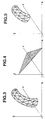
- Fig. 3 is a perspective illustration of an example of an object to be displayed by the apparatus of Fig. 1.
- Fig. 4 is a perspective illustration of an example of a cutting plane to be specified in the apparatus of Fig. 1.
- Fig. 5 is a perspective illustration of the object of Fig. 3 with a cross section at the cutting plane of Fig 4.
- Fig. 6 is a display of the apparatus of Fig. 1 with the cross section left open.
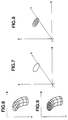
- Fig. 7 is a perspective illustration of a cutting edge at the cross section of Fig. 5.
- Fig. 8 is a perspective illustration of the cutting edge of Fig. 7 with its interior region painted out.
- Fig. 9 is a display of the apparatus of Fig. 1 with the cross section painted out.
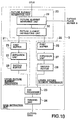
- Fig. 10 is a block diagram of an edge extraction unit of the apparatus of Fig. 1.
- Fig. 11 is a perspective illustration of another example of a cutting plane to be specified in the apparatus of Fig. 1 for explaining he operation of the edge extraction unit of Fig. 10.
- Fig. 12 is a perspective illustration of another example of an object to be displayed by the apparatus of Fig. 1 for explaining he operation of the edge extraction unit of Fig. 10.
- Fig. 13 is a cross sectional view of the cutting edge of Fig. 11 and the object of Fig. 12 for explaining he operation of the edge extraction unit of Fig. 10.
- Fig. 14 is another cross sectional view of the cutting edge of Fig. 11 and the object of Fig. 12 for explaining he operation of the edge extraction unit of Fig. 10.
- Fig. 15 is an illustration of the picture elements to be processed in the edge extraction unit of Fig. 10 at one stage of its operation.
- Fig. 16 is another illustration of the picture elements to be processed in the edge extraction unit of Fig. 10 at another stage of its operation.
- Fig. 17 is another illustration of the picture elements to be processed in the edge extraction unit of Fig. 10 at another stage of its operation.
- Fig. 18 is another illustration of the picture elements to be processed in the edge extraction unit of Fig. 10 at another stage of its operation.
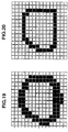
- Fig. 19 is another illustration of the picture elements to be processed in the edge extraction unit of Fig. 10 at another stage of its operation.
- Fig. 20 is another illustration of the picture elements to be processed in the edge extraction unit of Fig. 10 at another stage of its operation.
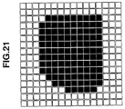
- Fig. 21 is an illustration of the picture elements to be displayed by the apparatus of Fig. 1 as a cross sectional image.
- FIG. 1 there is shown one embodiment of an apparatus for three dimensional display according to the present invention.
- the apparatus comprises a surface data memory 1 for storing surface data representing a surface of a three dimensional object to be displayed, a buffer unit 2 for temporarily storing various data necessary in producing a display image, an edge extraction unit 3 for extracting a cutting edge of a cross section, a painting unit 4 for painting out the extracted cutting edge of the cross section, a CPU 5 for coordinating operations of the apparatus and performing various calculations necessary in the operations, and a display unit 6 for displaying the three dimensional object with the cross section.
- a surface data memory 1 for storing surface data representing a surface of a three dimensional object to be displayed
- a buffer unit 2 for temporarily storing various data necessary in producing a display image
- an edge extraction unit 3 for extracting a cutting edge of a cross section
- a painting unit 4 for painting out the extracted cutting edge of the cross section
- a CPU 5 for coordinating operations of the apparatus and performing various calculations necessary in the operations
- a display unit 6 for displaying the three dimensional object with the cross section.
- an image of the surface cut at the cutting plane are generated from the surface data and data representing the cutting plane by utilizing a so called Z-buffer algorithm, while an image of the cross section is also generated from the surface data and the data representing the cutting plane, which is superposed on the surface image in a final display.
- the surface data memory 1 stores the surface data in a form of a collection of triangular patches, each of which is given by X, Y, and Z coordinates of three vertices and a luminance of a triangle specified by the three vertices, as shown in Fig. 2.
- the buffer unit 2 includes an I-buffer 7 for storing the luminance of the surface to be displayed at each X and Y coordinates of a display plane, which is taken to be a X-Y plane in this embodiment, a Z-buffer 8 for storing Z coordinates of the surface to be displayed at each X and Y coordinates of the display plane, a cutting plane buffer 9 for storing cutting plane data, a cutting edge buffer 10 for storing the cutting edge of the cross section at the cutting plane, and a cross section buffer 11 for storing data of cross sectional image to be superposed on the surface image.
- I-buffer 7 for storing the luminance of the surface to be displayed at each X and Y coordinates of a display plane, which is taken to be a X-Y plane in this embodiment
- a Z-buffer 8 for storing Z coordinates of the surface to be displayed at each X and Y coordinates of the display plane
- a cutting plane buffer 9 for storing cutting plane data
- a cutting edge buffer 10 for storing
- the cutting plane is specified externally by an operator from which the cutting plane data to be entered to the cutting plane buffer 9 are calculated by the CPU 5, whereas data stored in the I-buffer 7, Z-buffer 8, the cutting edge buffer 10, and the cross section buffer 11 are changed in a course of operations to generate display images.
- I-buffer 7, Z-buffer 8 cutting plane buffer 9, cutting edge buffer 10, and cross section buffer 11, two dimensional memory addresses represent X and Y coordinates, and memorized quantity at each address represents the luminance in a case of the I-buffer 7 and the Z coordinate in cases of the other buffers. It is to be noted that contents of the I-buffer 7 effectively represents the surface to be displayed with the cross section excluded.
- the edge extraction unit 3 extracts the cutting edge of the cross section at the cutting plane from the cutting plane data in the cutting plane buffer 9 and the surface data in the surface data memory 1 obtained through the CPU 5, and stores the extracted cutting edge in the cutting edge buffer 10. This edge extraction unit 3 will be described in further detail below.
- the painting unit 4 takes the cutting edge stored in the cutting edge buffer 10 and paint out its interior region with a prescribed color different from that of the surface in order to obtain the cross sectional image, and stores the obtained cross sectional image in the cross section buffer 11.
- the CPU 5 reads out the surface data from the surface data memory 1, calculates the luminance and the Z coordinate at each X and Y coordinates of the display plane from the surface data, and enters the appropriate luminance and 2 coordinates into the I-buffer 7 and the Z-buffer 8, respectively, in order to obtain the surface image, as will be described in detail below. Meanwhile, the CPU 5 also controls the operations of the edge extraction unit 3 and the painting unit 4 in order to obtain the cross sectional image.
- the display unit 6 superposes the cross sectional image on the surface image, and display the three dimensional object with the cross section looked from a X-Y plane.
- CPU 5 reads out the surface data from the surface data memory 1, and calculates the luminance and the Z coordinate at each X and Y coordinates of the display plane from the surface data.
- the CPU 5 reads out the Z coordinate stored in the Z-buffer 8 for each X and Y coordinates, and compares the Z coordinate calculated from the surface data and the Z coordinate read from the Z-buffer 8. If the calculated Z coordinate is closer to a X-Y plane, this calculated Z coordinate is entered into the Z-buffer 8 and the corresponding luminance is entered into the corresponding address of the I-buffer 7, whereas otherwise the Z-buffer 8 and the I-buffer 7 are left unchanged.
- the luminances and Z coordinates of each portion of the surface which are visible from X-Y plane and are therefore to be displayed can be obtained in the I-buffer 7 and Z-buffer 8.
- the CPU 5 calculates Z coordinates of the cutting plane at each X and Y coordinates and stores them as the cutting plane data in the cutting plane buffer 9.
- the CPU 5 reads out the surface data from the surface data memory 1, and calculates the luminance and the Z coordinate at each X and Y coordinates of the display plane from the surface data, as in the previous case.
- the CPU 5 reads out the Z coordinate stored in the cutting plane buffer 9 for each X and Y coordinates, and compares the Z coordinate calculated from the surface data and the Z coordinate read from the cutting plane buffer 9. If the calculated Z coordinate is closer to a X-Y plane, a picture element corresponding to these X, Y, and Z coordinates is labeled invalid so as not to be displayed, whereas otherwise the picture element is labeled valid.
- the CPU 5 reads out the Z coordinate stored in the Z-buffer 8 for each X and Y coordinates, and compares the Z coordinate calculated from the surface data and the Z coordinate read from the Z-buffer 8. If the calculated Z coordinate is closer to a X-Y plane, this calculated Z coordinate is entered into the Z-buffer 8 and the corresponding luminance is entered into the corresponding address of the I-buffer 7, whereas otherwise the Z-buffer 8 and the I-buffer 7 are left unchanged.
- the luminances and Z coordinates of each portion of the surface which are visible from X-Y plane and are therefore to be displayed can be obtained in the I-buffer 7 and Z-buffer 8, such that a display in which the cross section is left open as shown in Fig. 6 is displayed at the display unit 6.
- the edge extraction unit 3 extracts the cutting edge shown in Fig. 7 from the cutting plane data in the cutting plane buffer 9 and the Z coordinate at each X and Y coordinates of the display plane obtained from the surface data by the CPU 5, and stores the Z coordinates of the cutting edge in the cutting edge buffer 10.
- the painting unit 4 paints out the interior region enclosed by the cutting edge by the prescribed color different from that of the surface as shown in Fig. 8 in order to obtain the cross sectional image, and stores the obtained cross sectional image in the cross section buffer 11.
- the display unit 6 superposes the cross sectional image in the cross section buffer 11 on the surface image in the I-buffer 7, and display the three dimensional object with the cross section distinctively painted out as shown in Fig. 9.
- edge extraction unit 3 and the painting unit 4 are carried out as follows.
- the edge extraction unit 3 in further detail comprises a picture element separation unit 20 for separating out picture elements of the display unit 6 in a vicinity of the cutting plane, an upper picture element processor 21 for image processing those picture elements among the separated picture elements which are located immediately above the cutting plane, a lower picture element processor 22 for image processing those picture elements among the separated picture elements which are located immediately below the cutting plane, an AND processor 23 for taking AND (or intersection) of the outputs of the upper and lower picture element processors 21 and 22, and a thinning unit 24 for thinning the output of the AND processor 23.
- a picture element separation unit 20 for separating out picture elements of the display unit 6 in a vicinity of the cutting plane
- an upper picture element processor 21 for image processing those picture elements among the separated picture elements which are located immediately above the cutting plane
- a lower picture element processor 22 for image processing those picture elements among the separated picture elements which are located immediately below the cutting plane
- an AND processor 23 for taking AND (or intersection) of the outputs of the upper and lower picture element processors 21 and 22, and a thinning
- the picture element separation unit 20 further comprises a picture element searching unit 29, in which whether each of the Z coordinates calculated from the surface data by the CPU 5 is within a prescribed range around the Z coordinates of the cutting plane in the cutting plane buffer 9 is checked by subtracting the Z coordinate of the cutting plane from the Z coordinate calculated from the surface data and comparing the difference with a magnitude of the prescribed range in order to search out the picture elements in the vicinity of the cutting plane, and a picture element distributing unit 30, in which the searched out picture elements are distributed to the upper and lower picture element processors 21 and 22 in accordance with the sign of the difference between the Z coordinate of the cutting plane and the Z coordinate calculated from the surface data, i.e., when the difference is positive the picture element is given to the upper picture element processor 21, whereas otherwise the picture element is given to the lower picture element processor 22.
- a picture element searching unit 29 in which whether each of the Z coordinates calculated from the surface data by the CPU 5 is within a prescribed range around the Z coordinates of the cutting plane in the cutting plane buffer 9 is checked by subtracting the
- the upper picture element processors 21 includes a first buffer 25 for temporarily storing the picture elements given from the picture element separation unit 20 in binary data, an expansion unit 27 for expanding the binarized picture elements into four nearest neighbors, and a second buffer 28 for temporarily storing the expanded picture elements.
- a first buffer 25 for temporarily storing the picture elements given from the picture element separation unit 20 in binary data
- an expansion unit 27 for expanding the binarized picture elements into four nearest neighbors
- a second buffer 28 for temporarily storing the expanded picture elements.
- the binarized picture elements at the first buffer 25 is as shown in Fig. 15
- the expanded picture elements at the expansion unit 27 is as shown in Fig. 16 in which triangles represents those picture elements expanded.
- the lower picture element processors 22 includes a first buffer 25 for temporarily storing the picture elements given from the picture element separation unit 20 in binary data, an expansion unit 27 for expanding the binarized picture elements into four nearest neighbors, and a second buffer 28 for temporarily storing the expanded picture elements.
- the binarized picture elements at the first buffer 25 is as shown in Fig. 17, and the expanded picture elements at the expansion unit 27 is as shown in Fig. 18 in which triangles represents those picture elements expanded.
- the AND of the expanded picture elements in the buffers 28 of the upper and lower picture element processors 21 and 22 are then taken at the AND processor 23, as shown in Fig. 19, and are then thinned at the thinning unit 24, as shown in Fig. 20 to obtain the cutting edge data to be stored in the cutting edge buffer 10.
- the cutting edge data thus obtained are then taken by the painting unit 4 which paints out the interior region enclosed by the cutting edge by the prescribed color as shown in Fig. 21.
- This can be achieved in any known method such as that utilizing the decomposition of the cutting edge into 4- or 8-connected closed loops, and the calculation of vector data for chain chords of each closed loop.
- the surface image with the cross section left open and the cross sectional image painted out in different color from the surface image are generated simultaneously and are displayed as the cross sectional image superposed on the surface image, so that an object with cross section can be displayed three dimensionally in real time.
Landscapes
- Physics & Mathematics (AREA)
- Engineering & Computer Science (AREA)
- Geometry (AREA)
- Computer Graphics (AREA)
- General Physics & Mathematics (AREA)
- Theoretical Computer Science (AREA)
- Software Systems (AREA)
- Image Generation (AREA)
Claims (8)
- Appareil destiné à l'affichage en trois dimensions d'un objet avec une section transversale, comprenant :un moyen de mémoire de données de surface (1) destiné à mémoriser des données de surface représentant une surface de l'objet sous forme d'une collection de figures à deux dimensions définies dans l'espace à trois dimensions,un moyen de tampon de plan de coupe (9) destiné à mémoriser des données de plan de coupe représentant un plan de coupe sur lequel s'appuie la section transversale,un moyen de génération d'image de la surface (5, 7, 8) destiné à générer une image de la surface, dans lequel l'objet est coupé au niveau du plan de la coupe et la section transversale est laissée ouverte, à partir des données de surface et des données de plan de coupe, etun moyen d'affichage (6) destiné à afficher l'image de la surface,un moyen de génération d'image de la section transversale (3, 4, 10, 11) destiné à générer une image de la section transversale, dans lequel une région intérieure de la section transversale est dessinée dans une couleur prescrite, à partir des données de surface et des données de plan de coupe,le moyen de génération d'image de la section transversale pouvant être mis en oeuvre pour générer l'image de la section transversale pendant une génération de l'image de la surface par le moyen de génération d'image de la surface, en parallèle avec une génération de l'image de la surface par le moyen de génération d'image de la surface, et ledit moyen d'affichage (6) pouvant être mis en oeuvre pour afficher l'image de la surface et l'image de la section transversale en superposant l'image de la section transversale telle qu'elle est générée par le moyen de génération d'image de la section transversale, sur l'image de la surface telle qu'elle est générée par le moyen de génération d'image de la surface.
- Appareil selon la revendication 1, dans lequel le moyen de génération d'image de la section transversale (3, 4, 10, 11) comprend :un moyen d'extraction de bord (3) destiné à extraire un bord de la coupe de l'objet au niveau du plan de la coupe à partir des données de surface et des données de plan de coupe, etun moyen de dessin (4) destiné à dessiner une région intérieure entourée par le bord de la coupe extrait, avec la couleur prescrite.
- Appareil selon la revendication 2, dans lequel le moyen d'extraction de bord (3) peut être mis en oeuvre pour extraire le bord de la coupe en recherchant les éléments d'image situés à proximité du plan de la coupe à l'intérieur d'une plage prescrite.
- Appareil selon la revendication 3, dans lequel le moyen d'extraction de bord (3) peut être mis en oeuvre pour extraire le bord de la coupe en prenant l'intersection d'une projection des éléments d'image situés immédiatement au-dessus du plan de la coupe et d'une projection des éléments d'image situés immédiatement en-dessous du plan de la coupe, en tant que bord de la coupe.
- Procédé d'affichage en trois dimensions d'un objet avec une section transversale, comprenant les étapes consistant à :mémoriser des données de surface représentant une surface de l'objet sous forme d'une collection de figures à deux dimensions définies dans un espace en trois dimensions.mémoriser des données de plan de coupe représentant un plan de coupe sur lequel s'appuie la section transversale,générer une image de la surface, dans laquelle l'objet est coupé au niveau du plan de la coupe et la section transversale est laissée ouverte, à partir des données de surface et des données de plan de coupe, etafficher l'image de la surface,générer une image de la section transversale, dans laquelle une région intérieure de la section transversale est dessinée dans une couleur prescrite, à partir des données de surface et des données de plan de coupe,l'image de la section transversale étant générée pendant une génération de l'image de la surface à l'étape de génération d'image de la surface, en parallèle avec une génération de l'image de la surface à l'étape de génération d'image de la surface, etafficher l'image de la surface et l'image de la section transversale en superposant l'image de la section transversale telle qu'elle est générée à l'étape de génération d'image de la section transversale sur l'image de la surface telle qu'elle est générée à l'étape de génération d'image de la surface.
- Procédé selon la revendication 5, dans lequel la génération de l'image de la section transversale comprend les étapes consistant à :extraire un bord de la coupe de l'objet au niveau du plan de la coupe à partir des données de surface et des données de plan de coupe, etdessiner une région intérieure entourée par le bord de la coupe extrait, avec la couleur prescrite.
- Procédé selon la revendication 6, dans lequel le bord de la coupe est extrait en recherchant les éléments d'image situés à proximité du plan de la coupe à l'intérieur d'une plage prescrite.
- Procédé selon la revendication 7, dans lequel le bord de la coupe est extrait en prenant l'intersection d'une projection des éléments d'image situés immédiatement au-dessus du plan de la coupe et d'une projection des éléments d'image situés immédiatement au-dessous du plan de la coupe, en tant que bord de la coupe.
Applications Claiming Priority (2)
| Application Number | Priority Date | Filing Date | Title |
|---|---|---|---|
| JP327903/88 | 1988-12-27 | ||
| JP63327903A JPH02173878A (ja) | 1988-12-27 | 1988-12-27 | 3次元断面表示装置 |
Publications (3)
| Publication Number | Publication Date |
|---|---|
| EP0376181A2 EP0376181A2 (fr) | 1990-07-04 |
| EP0376181A3 EP0376181A3 (fr) | 1992-04-08 |
| EP0376181B1 true EP0376181B1 (fr) | 1997-07-23 |
Family
ID=18204282
Family Applications (1)
| Application Number | Title | Priority Date | Filing Date |
|---|---|---|---|
| EP89123730A Expired - Lifetime EP0376181B1 (fr) | 1988-12-27 | 1989-12-22 | Méthode et appareil d'affichage de coupe en trois dimensions |
Country Status (4)
| Country | Link |
|---|---|
| US (1) | US5309550A (fr) |
| EP (1) | EP0376181B1 (fr) |
| JP (1) | JPH02173878A (fr) |
| DE (1) | DE68928198T2 (fr) |
Families Citing this family (15)
| Publication number | Priority date | Publication date | Assignee | Title |
|---|---|---|---|---|
| US5448696A (en) * | 1990-11-30 | 1995-09-05 | Hitachi, Ltd. | Map information system capable of displaying layout information |
| CA2060975C (fr) * | 1991-02-25 | 1998-11-10 | Gopalan Ramanujam | Systeme de visualisation scientifique |
| US5493653A (en) * | 1991-03-18 | 1996-02-20 | Schmidt; Daniel G. | Computer graphics system and method for capping volume enclosing polyhedron after sectioning |
| EP0549189B1 (fr) * | 1991-12-23 | 2003-05-07 | General Electric Company | Génération de modèles solides par une méthode d'évaluation de dimension utilisant des cubes divisants |
| EP0549183B1 (fr) * | 1991-12-23 | 2003-05-14 | General Electric Company | Système pour l'affichage de coupes solides pour les surfaces de modèles solides |
| EP0549182A2 (fr) * | 1991-12-23 | 1993-06-30 | General Electric Company | Appareil et procédé pour l'affichage de coupes chirurgicales dans des modèles tri-dimensionnels |
| EP0549185A2 (fr) * | 1991-12-23 | 1993-06-30 | General Electric Company | Système pour la conversion à balayage tri-dimensionnel d'un modèle polygonal dans un format "point et normale", affiché avec l'utilisation d'un circuit accélérateur |
| US5428716A (en) * | 1991-12-26 | 1995-06-27 | International Business Machines Corporation | Solid-clip methodology and architecture for clipping solid models and displaying cross-sections using depth-buffers |
| USH1530H (en) * | 1993-06-17 | 1996-05-07 | Ultrapointe Corporation | Surface extraction from a three-dimensional data set |
| DE69622900T2 (de) * | 1995-03-17 | 2003-04-10 | Canon K.K., Tokio/Tokyo | Verfahren und Gerät zur dreidimensionalen Bildverarbeitung |
| US6226003B1 (en) * | 1998-08-11 | 2001-05-01 | Silicon Graphics, Inc. | Method for rendering silhouette and true edges of 3-D line drawings with occlusion |
| JP2000051202A (ja) * | 1998-08-14 | 2000-02-22 | Ge Yokogawa Medical Systems Ltd | 画像表示方法および画像表示装置 |
| GB2372188B (en) * | 2001-02-08 | 2005-07-13 | Imagination Tech Ltd | Volume clipping in computer 3-D Graphics |
| JP2006505174A (ja) * | 2002-11-01 | 2006-02-09 | コーニンクレッカ フィリップス エレクトロニクス エヌ ヴィ | 三次元ディスプレイ |
| WO2004111887A1 (fr) * | 2003-06-10 | 2004-12-23 | Fujitsu Limited | Programme d'assistance de type tridimensionnel |
Family Cites Families (6)
| Publication number | Priority date | Publication date | Assignee | Title |
|---|---|---|---|---|
| US4737921A (en) * | 1985-06-03 | 1988-04-12 | Dynamic Digital Displays, Inc. | Three dimensional medical image display system |
| US4719585A (en) * | 1985-08-28 | 1988-01-12 | General Electric Company | Dividing cubes system and method for the display of surface structures contained within the interior region of a solid body |
| US4879668A (en) * | 1986-12-19 | 1989-11-07 | General Electric Company | Method of displaying internal surfaces of three-dimensional medical images |
| US4882679A (en) * | 1987-11-27 | 1989-11-21 | Picker International, Inc. | System to reformat images for three-dimensional display |
| US4907174A (en) * | 1988-06-02 | 1990-03-06 | Sun Microsystems, Inc. | Z-buffer allocated for window identification |
| US4984157A (en) * | 1988-09-21 | 1991-01-08 | General Electric Company | System and method for displaying oblique planar cross sections of a solid body using tri-linear interpolation to determine pixel position dataes |
-
1988
- 1988-12-27 JP JP63327903A patent/JPH02173878A/ja active Pending
-
1989
- 1989-12-22 EP EP89123730A patent/EP0376181B1/fr not_active Expired - Lifetime
- 1989-12-22 DE DE68928198T patent/DE68928198T2/de not_active Expired - Fee Related
-
1992
- 1992-12-30 US US07/996,493 patent/US5309550A/en not_active Expired - Lifetime
Also Published As
| Publication number | Publication date |
|---|---|
| EP0376181A3 (fr) | 1992-04-08 |
| US5309550A (en) | 1994-05-03 |
| JPH02173878A (ja) | 1990-07-05 |
| DE68928198D1 (de) | 1997-08-28 |
| DE68928198T2 (de) | 1997-12-18 |
| EP0376181A2 (fr) | 1990-07-04 |
Similar Documents
| Publication | Publication Date | Title |
|---|---|---|
| US5309550A (en) | Method and apparatus for three dimensional display with cross section | |
| Ayache | Artificial vision for mobile robots: stereo vision and multisensory perception | |
| US5877768A (en) | Method and system using a sorting table to order 2D shapes and 2D projections of 3D shapes for rendering a composite drawing | |
| EP0638875B1 (fr) | Appareil et méthode pour génération d'animation en 3 dimensions | |
| EP0587138A2 (fr) | Dispositif d'interface humaine tri-dimensionnelle utilisant la reconnaissance de mouvements à l'aide d'un traitement dynamique d'images | |
| JPH05114032A (ja) | 3次元グラフイツクスにおけるシヤドウ・テスト方法 | |
| US8660305B2 (en) | Method and apparatus for removing a visual object from a visual data stream | |
| GB2244412A (en) | Simulating non-homogeneous fog with a plurality of translucent layers | |
| JP2572515B2 (ja) | 画素処理方法及び装置並びにグラフィックバッファ | |
| JP2001067463A (ja) | 異なる視点からの複数のフェイシャル画像に基づき新たな視点からのフェイシャル画像を生成するフェイシャル画像生成装置及び方法並びにその応用装置及び記録媒体 | |
| EP1445736B1 (fr) | Procédé et système fournissant une représentation volumique d'un objet tridimensionel | |
| US5086496A (en) | Method for hidden line and surface removal in a three dimensional display | |
| JP3954178B2 (ja) | 3次元地図表示装置 | |
| EP1111546B1 (fr) | Techniques d'affichage pour réalité virtuelle tridimensionnelle | |
| EP0382495A2 (fr) | Appareil de traitement de figure | |
| JP2634126B2 (ja) | グラフィックス表示方法および装置 | |
| EP0549183B1 (fr) | Système pour l'affichage de coupes solides pour les surfaces de modèles solides | |
| JPH10111934A (ja) | 3次元形状モデル作成方法及び媒体 | |
| EP0364243B1 (fr) | Méthode de traitement de géométrie à trois dimensions et dispositif à cet effet | |
| EP0507548A2 (fr) | Texture pour la génération d'images en temps réel | |
| Chabbi et al. | A combined use of regions and segments to construct facets | |
| JP2574315B2 (ja) | 模擬視界発生装置 | |
| Tomlinson | An aid to hidden surface removal in real time CGI systems | |
| JPH0773342A (ja) | 画像生成装置 | |
| JPS63167977A (ja) | 3次元形状ピツク方法 |
Legal Events
| Date | Code | Title | Description |
|---|---|---|---|
| PUAI | Public reference made under article 153(3) epc to a published international application that has entered the european phase |
Free format text: ORIGINAL CODE: 0009012 |
|
| 17P | Request for examination filed |
Effective date: 19891222 |
|
| AK | Designated contracting states |
Kind code of ref document: A2 Designated state(s): DE FR GB |
|
| PUAL | Search report despatched |
Free format text: ORIGINAL CODE: 0009013 |
|
| AK | Designated contracting states |
Kind code of ref document: A3 Designated state(s): DE FR GB |
|
| 17Q | First examination report despatched |
Effective date: 19950324 |
|
| GRAG | Despatch of communication of intention to grant |
Free format text: ORIGINAL CODE: EPIDOS AGRA |
|
| GRAH | Despatch of communication of intention to grant a patent |
Free format text: ORIGINAL CODE: EPIDOS IGRA |
|
| GRAH | Despatch of communication of intention to grant a patent |
Free format text: ORIGINAL CODE: EPIDOS IGRA |
|
| GRAA | (expected) grant |
Free format text: ORIGINAL CODE: 0009210 |
|
| AK | Designated contracting states |
Kind code of ref document: B1 Designated state(s): DE FR GB |
|
| REF | Corresponds to: |
Ref document number: 68928198 Country of ref document: DE Date of ref document: 19970828 |
|
| ET | Fr: translation filed | ||
| PLBE | No opposition filed within time limit |
Free format text: ORIGINAL CODE: 0009261 |
|
| STAA | Information on the status of an ep patent application or granted ep patent |
Free format text: STATUS: NO OPPOSITION FILED WITHIN TIME LIMIT |
|
| 26N | No opposition filed | ||
| REG | Reference to a national code |
Ref country code: GB Ref legal event code: 746 Effective date: 19980929 |
|
| REG | Reference to a national code |
Ref country code: FR Ref legal event code: D6 |
|
| REG | Reference to a national code |
Ref country code: GB Ref legal event code: IF02 |
|
| PGFP | Annual fee paid to national office [announced via postgrant information from national office to epo] |
Ref country code: FR Payment date: 20061208 Year of fee payment: 18 |
|
| PGFP | Annual fee paid to national office [announced via postgrant information from national office to epo] |
Ref country code: DE Payment date: 20061214 Year of fee payment: 18 |
|
| PGFP | Annual fee paid to national office [announced via postgrant information from national office to epo] |
Ref country code: GB Payment date: 20061220 Year of fee payment: 18 |
|
| GBPC | Gb: european patent ceased through non-payment of renewal fee |
Effective date: 20071222 |
|
| PG25 | Lapsed in a contracting state [announced via postgrant information from national office to epo] |
Ref country code: DE Free format text: LAPSE BECAUSE OF NON-PAYMENT OF DUE FEES Effective date: 20080701 |
|
| REG | Reference to a national code |
Ref country code: FR Ref legal event code: ST Effective date: 20081020 |
|
| PG25 | Lapsed in a contracting state [announced via postgrant information from national office to epo] |
Ref country code: GB Free format text: LAPSE BECAUSE OF NON-PAYMENT OF DUE FEES Effective date: 20071222 |
|
| PG25 | Lapsed in a contracting state [announced via postgrant information from national office to epo] |
Ref country code: FR Free format text: LAPSE BECAUSE OF NON-PAYMENT OF DUE FEES Effective date: 20071231 |