EP0376242B1 - Mécanisme de chargement de cassette utilisé dans un appareil d'enregistrement/reproduction - Google Patents
Mécanisme de chargement de cassette utilisé dans un appareil d'enregistrement/reproduction Download PDFInfo
- Publication number
- EP0376242B1 EP0376242B1 EP89123933A EP89123933A EP0376242B1 EP 0376242 B1 EP0376242 B1 EP 0376242B1 EP 89123933 A EP89123933 A EP 89123933A EP 89123933 A EP89123933 A EP 89123933A EP 0376242 B1 EP0376242 B1 EP 0376242B1
- Authority
- EP
- European Patent Office
- Prior art keywords
- tape
- guide roller
- guide
- preventing means
- damage preventing
- Prior art date
- Legal status (The legal status is an assumption and is not a legal conclusion. Google has not performed a legal analysis and makes no representation as to the accuracy of the status listed.)
- Expired - Lifetime
Links
- 230000007246 mechanism Effects 0.000 title claims description 57
- 238000004804 winding Methods 0.000 claims description 21
- 238000010276 construction Methods 0.000 description 19
- 230000037431 insertion Effects 0.000 description 4
- 238000003780 insertion Methods 0.000 description 4
- 238000011144 upstream manufacturing Methods 0.000 description 2
- 238000010586 diagram Methods 0.000 description 1
Images


Classifications
-
- G—PHYSICS
- G11—INFORMATION STORAGE
- G11B—INFORMATION STORAGE BASED ON RELATIVE MOVEMENT BETWEEN RECORD CARRIER AND TRANSDUCER
- G11B15/00—Driving, starting or stopping record carriers of filamentary or web form; Driving both such record carriers and heads; Guiding such record carriers or containers therefor; Control thereof; Control of operating function
- G11B15/60—Guiding record carrier
- G11B15/66—Threading; Loading; Automatic self-loading
- G11B15/665—Threading; Loading; Automatic self-loading by extracting loop of record carrier from container
- G11B15/6653—Threading; Loading; Automatic self-loading by extracting loop of record carrier from container to pull the record carrier against drum
- G11B15/6656—Threading; Loading; Automatic self-loading by extracting loop of record carrier from container to pull the record carrier against drum using two-sided extraction, i.e. "M-type"
Definitions
- various operation modes such as recording, play, freeze (i.e., still image reproduction), slow play, fast-forward play, fast-rewind play, fast forward, and fast rewind, are selectively established with a mode-establishing mechanism and its associated circuits. If an eject key is operated, the tape-loading mechanism draws the tape back into the cassette, and the front loading mechanism returns the cassette from the cassette-loading position to the cassette insertion port.
- the tape loading mechanism of this apparatus for bringing a tape into contact with a drum carrying the heads for recording or reproducing comprises a pair of tape pulling members which depending on a set function of the apparatus move along guides in predetermined directions for pulling the tape out of a cassette and guiding it on a predetermined tape travel path or for returning the tape into the cassette.
- Each of the movable tape pulling members comprises a tape guide roller and holding members are provided at the guide end positions for holding the respective tape pulling members at these positions.
- no means are provided for preventing a damage of the tape when the latter slackens and is disengaged from the tape guide rollers.
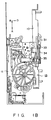
- Figs. 1A, 1B and 1C are top, side and bottom views, respectively, of a tape-loading mechanism employed in the magnetic recording/reproducing apparatus according to the first embodiment of the present invention.
- frame member 11 is coupled to one end of main chassis 10.
- Cassette holder 12 is supported by frame member 11 such that it is movable in the directions indicated by arrows A, B and D (the direction indicated by arrow D is perpendicular to the directions indicated by arrows A and B).
- Cassette holder 12 is adapted to receive cassette C (which is not shown in Figs. 1A, 1B and 1C, for simplicity) when it is located at the cassette insertion port.
- front loading mechanism 13 In response to the insertion of cassette C into cassette holder 12, front loading mechanism 13 is automatically driven. This front loading mechanism moves cassette holder 12 in direction B, together with cassette C inserted therein, until cassette holder 12 reaches a predetermined position. Then, front loading mechanism 13 moves cassette holder 12 in direction D. As a result, cassette C is fitted on supply reel bases 14 and 15, which are parts of a tape-driving mechanism.
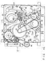
- driving gear 29 is fitted around the periphery of the rotating member of capstan motor 27.
- Vertically-movable gear 30 is arranged such that it faces driving gear 29.
- First end 31a of vertically-swingable switch lever 31 is in contact with the upper side of vertically-movable gear 30.
- Second end 31b of the switch lever 31 engageable with one side of first mode-switching cam 32a, which is one of the axially-arranged mode-switching cams of the operation mode-switching mechanism.
- vertically-movable gear 30 is coaxial with pulley 33, and this pulley 33 is coupled to main chassis 10 such that it is rotatable around shaft 33a.
- Vertically-movable gear 30 is located around pulley 33 and is urged toward pulley 33 in the axial direction of shaft 33a by spring 30a. The rotation of vertically-movable gear 30 is transmitted to pulley 33 through stop members 33b. That is, vertically-movable gear 30 and pulley 33 are rotatable in the same direction.
- first and second tape-pulling members 39a and 39b are fitted in first and second guide holes 38a and 38b, respectively, such that they are movable within the guide holes.
- Slanted post 40a substantially parallel to cylinder 37 and guide roller 41a substantially perpendicular to main chassis 10 are provided for first tape-pulling member 39a such that they are located side by side with reference to each other.
- slanted post 40b substantially parallel to cylinder 37 and guide roller 41b substantially perpendicular to main chassis 10 are provided for second tape-pulling member 39b such that they are located side by side with reference to each other.
- Pin 45b located at the other end of driving lever 45 engages with cam groove 32f formed in second mode-switching cam 32e, and this cam 32e is rotated within a predetermined angular range by loading motor 32. Therefore, driving lever 45 is driven by the movement of second mode-switching cam 32e, and transmits the driving force to first and second tape-pulling members 39a and 39b, through half-gear 44, first and second driving gears 43a and 43b, and first and second links 42a and 42b, thereby performing tape loading.
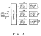
- First and second mode-switching cams 32a and 32e mentioned above are coaxial with the other mode-switching cams (not shown). All these mode-switching cams are rotated within the same angular range by loading motor 32, and their angles of rotation are determined in accordance with the operation modes of the VTR. As is shown in Fig. 6, loading motor 32 is driven by motor driver 65 under the control of controller 66. In accordance with the user's operation of control panel 67, controller 66 determines an operation mode of the VTR. Controller 66 causes the mode-switching cams to be rotated by the angle corresponding to the determined operation mode. Further, controller 66 controls motor driver 68 in accordance with the determined operation mode, to thereby drive capstan motor 27.
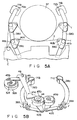
- the holding members 71a, 71b and the tape control portions 72a, 72b have the constructions shown in Figs. 7A to 7C. As is shown in these Figures, tape control portions 72a and 72b are provided in correspondence to one side facing cylinder 37 on holding members 71a and 71b. The heights of tape control portions 72a and 72b as measured from holding members 71a and 71b are determined such that their upper surfaces are substantially at the same level as, or slightly lower than, flanges 74a and 74b formed at the lower end of tape-winding portions 73a and 73b of guide rollers 41a and 41b.
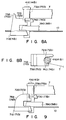
- Figs. 8A and 8B are views of tape control portions 72a and 72b employed in the tape-loading mechanism of the second embodiment of the present invention. Since tape control portions 72a and 72b differ from each other merely in their positions relative to respective guide rollers 41a and 41b, only the construction including first tape-pulling member 39a is shown in Figs. 8A and 8B, for simplicity. As for the construction including second tape-pulling member 39b, the corresponding parts are denoted by the reference numerals enclosed within the parentheses.
- tape control portion 72a corresponding to first tape-pulling member 39a is integral with holding member 71a.
- tape control portion 72a is constituted by the upper surface of holding member 71a.
- tape control section 72a is located only on one side of guide roller 41a, whereas in the second embodiment, it is constituted by the entire upper surface of holding member 71a and is located on both sides of guide roller 41a.
- projection 75a used for guiding tape T is formed on the surface of holding member 71a, i.e., on tape control portion 72a.
- Holding member 71b corresponding to second tape-pulling member 39b has tape control portion 72b and projection 75b, which have similar constructions to tape control portion 72a and projection 75a mentioned above.
- tape control portion 72a corresponding to first tape-pulling member 39a is integral with holding member 71a.
- tape control portion 72a is constituted by the upper surface of holding member 71a.
- Slanted portion 76a which is slanted at a predetermined angle and serves to guide slack of tape T, is formed at that end of tape control portion 72a (i.e., holding member 71a ) which is located opposite to guide roller 41a.
- Holding member 71b corresponding to second tape-pulling member 39b has tape control section 72b and slanted portion 76b similar to those mentioned above.
- the present invention is not limited to this. It can be applied to various types of magnetic recording/reproducing apparatuses, and similar advantages to those mentioned above can be expected in such application as well.
Landscapes
- Replacement Of Web Rolls (AREA)
- Registering, Tensioning, Guiding Webs, And Rollers Therefor (AREA)
- Automatic Tape Cassette Changers (AREA)
Claims (8)
- Mécanisme de chargement de bande pour extraire une bande (T) d'une cassette de bande (C) et pour amener la bande (T) en contact avec un tambour (37) utilisé pour l'enregistrement/reproduction d'information sur la bande (T) le mécanisme comprenant :
un premier élément d'extraction de bande (39a), disposé du côté entrée de bande du tambour (37) et portant une première tige oblique (40a) et un premier galet de guidage (41a), pour extraire la bande (T) de la cassette de bande (C), la première tige oblique (40a) et le premier galet de guidage (41a) contactant la bande (T), le premier galet de guidage (41a) comprenant une première partie d'enroulement de bande (73a), la bande (T) passant autour de la première partie d'enroulement de bande (73a) lorsque la bande (T) contacte le premier galet de guidage (41a) ;
un premier moyen de guidage (38a), disposé du côté entrée de bande du tambour (37), pour guider le premier élément d'extraction de bande (39a) entre des première et seconde positions, la première tige oblique (40a) et le premier galet de guidage (41a) du premier élément d'extraction de bande (39a) contactant initialement la bande (T) contenue dans la cassette de bande (C) au droit de la première position, et le premier élément d'extraction de bande (39a) amenant la bande (T) extraite de la cassette de bande (C) en contact avec le tambour (37) au droit de la seconde position ;
un premier élément de maintien (71a) pour maintenir, au droit de la seconde position, le premier élément d'extraction de bande (39a) guidé depuis la première position par le premier moyen de guidage (38a) ;
un second élément d'extraction de bande (39b), disposé du côté sortie de bande du tambour (37) et portant une seconde tige oblique (40b) et un second galet de guidage (41b), pour extraire la bande (T) de la cassette de bande (C), la seconde tige oblique (40b) et le second galet de guidage (41b) contactant la bande (T), le second galet de guidage (41b) comprenant une seconde partie d'enroulement de bande (73b), la bande (T) passant autour de la seconde partie d'enroulement de bande (73b) lorsque la bande (T) contacte le second galet de guidage (41b) ;
un second moyen de guidage (38b), disposé du côté sortie de bande du tambour (37), pour guider le second élément d'extraction de bande (39b) entre des troisième et quatrième positions, la seconde tige oblique (40b) et le second galet de guidage (41b) du second élément d'extraction de bande (39b) contactant initialement la bande (T) contenue dans la cassette de bande (C) au droit de la troisième position, et le second élément d'extraction de bande (39b) amenant la bande (T) extraite de la cassette de bande (C) en contact avec le tambour (37) au droit de la quatrième position ;
un second élément de maintien (71b) pour maintenir, au droit de la quatrième position, le second élément d'extraction de bande (39b) guidé depuis la troisième position par le second moyen de guidage (38b) ;
caractérisé en ce qu'il comprend en outre :
un premier moyen de prévention de dommages (72a), formé sur le premier élément de maintien (71a) de telle manière que le premier moyen de prévention de dommages (72a) soit placé, par rapport à au moins l'un d'un côté entrée de bande et d'un côté sortie de bande du premier galet de guidage (41a) du premier élément d'extraction de bande (39a), pour empêcher la bande (T) d'être endommagée lorsque la bande (T) tombe du premier galet de guidage (41a) dans un état détendu, le premier moyen de prévention de dommages (72a) supportant seulement le bord inférieur de la bande (T) à un niveau correspondant à l'extrémité inférieure de la première partie d'enroulement de bande (73a) du premier galet de guidage (41a), en laissant non supportés l'autre bord et les faces de la bande (T), de sorte que s'il arrive que la bande (T) dans un état détendu quitte le premier de galet de guidage (41a), le bord inférieur de la bande détendue (T) reposera sur le premier moyen de prévention de dommages (72a) ; et
un second moyen de prévention de dommages (72b), formé sur le second élément de maintien (71b) de telle manière que le second moyen de prévention de dommages (72b) soit placé, par rapport à au moins l'un d'un côté entrée de bande et d'un côté sortie de bande du second galet de guidage (41b) du second élément d'extraction de bande (39b), pour empêcher la bande (T) d'être endommagée lorsque la bande (T) tombe du second galet de guidage (41b) dans un état détendu, le second moyen de prévention de dommages (72b) supportant seulement le bord inférieur de la bande (T) à un niveau correspondant à l'extrémité inférieure de la seconde partie d'enroulement de bande (73b) du second galet de guidage (41b), en laissant non supportés l'autre bord et les faces de la bande (T), de sorte que s'il arrive que la bande (T) dans un état détendu quitte le second de galet de guidage (41b), le bord inférieur de la bande détendue (T) reposera sur le second moyen de prévention de dommages (72b). - Mécanisme de chargement de bande selon la revendication 1, caractérisé en ce que :
lesdits galets de guidage (41a, 41b) comprennent des collerettes (74a, 74b) qui définissent des extrémités inférieures des parties d'enroulement de bande (73a, 73b) ; et,
en ce que lesdits premier et second moyens de prévention de dommages (72a, 72b) sont sensiblement au même niveau que les collerettes (74a, 74b). - Mécanisme de chargement de bande selon la revendication 1, caractérisé en ce que :
lesdits galets de guidage (41a, 41b) comprennent des collerettes (74a, 74b) qui définissent des extrémités inférieures des parties d'enroulement de bande (73a, 73b) ; et,
en ce que lesdits premier et second moyens de prévention de dommages (72a, 72b) sont à un niveau légèrement plus bas que celui des collerettes (74a, 74b). - Mécanisme de chargement de bande selon l'une quelconque des revendications 1 à 3, caractérisé en ce que lesdits premier et second moyens de prévention de dommages (72a, 72b) ont des extrémités qui s'étendent de manière à croiser le trajet de bande.
- Mécanisme de chargement de bande selon l'une quelconque des revendications 1 à 3, caractérisé en ce que lesdits premier et second moyens de prévention de dommages (72a, 72b) sont d'un seul tenant avec les premier et second éléments de maintien (71a, 71b) et sont constitués par les surfaces supérieures des premier et second éléments de maintien (71a, 71b).
- Mécanisme de chargement de bande selon la revendication 5, caractérisé en ce que lesdits premier et second moyens de prévention de dommages (72a, 72b) comprennent des parties de guidage de bande, situées à une distance prédéterminée des galets de guidage (41a, 41b), pour guider le mou de la bande.
- Mécanisme de chargement de bande selon la revendication 6, caractérisé en ce que lesdites parties de guidage de bande comprennent des saillies (75a, 75b) pour guider le mou de la bande, lesdites saillies étant formées aux extrémités des premier et second moyens de prévention de dommages (72a, 72b) qui sont situées à l'opposé des galets de guidage (41a, 41b).
- Mécanisme de chargement de bande selon la revendication 6, caractérisé en ce que lesdites parties de guidage de bande comprennent des parties obliques (76a, 76b) pour guider le mou de la bande, lesdites parties obliques étant formées aux extrémités des premier et second moyens de prévention de dommages (72a, 72b) qui sont situées à l'opposé des galets de guidage (41a, 41b).
Applications Claiming Priority (2)
| Application Number | Priority Date | Filing Date | Title |
|---|---|---|---|
| JP333589/88 | 1988-12-28 | ||
| JP63333589A JP2675602B2 (ja) | 1988-12-28 | 1988-12-28 | テープローディング装置 |
Publications (3)
| Publication Number | Publication Date |
|---|---|
| EP0376242A2 EP0376242A2 (fr) | 1990-07-04 |
| EP0376242A3 EP0376242A3 (fr) | 1991-09-11 |
| EP0376242B1 true EP0376242B1 (fr) | 1994-08-17 |
Family
ID=18267733
Family Applications (1)
| Application Number | Title | Priority Date | Filing Date |
|---|---|---|---|
| EP89123933A Expired - Lifetime EP0376242B1 (fr) | 1988-12-28 | 1989-12-27 | Mécanisme de chargement de cassette utilisé dans un appareil d'enregistrement/reproduction |
Country Status (4)
| Country | Link |
|---|---|
| EP (1) | EP0376242B1 (fr) |
| JP (1) | JP2675602B2 (fr) |
| KR (1) | KR930009656B1 (fr) |
| DE (1) | DE68917575T2 (fr) |
Families Citing this family (1)
| Publication number | Priority date | Publication date | Assignee | Title |
|---|---|---|---|---|
| US5801898A (en) * | 1995-04-10 | 1998-09-01 | Sanyo Electric Co., Ltd. | Loading mechanism of magnetic recording-reproduction apparatus and method of assembling the mechanism |
Family Cites Families (4)
| Publication number | Priority date | Publication date | Assignee | Title |
|---|---|---|---|---|
| US4138699A (en) * | 1976-06-04 | 1979-02-06 | Victor Company Of Japan, Ltd. | Automatic tape loading type recording and/or reproducing apparatus |
| DE3509176A1 (de) * | 1985-03-14 | 1986-09-18 | Grundig E.M.V. Elektro-Mechanische Versuchsanstalt Max Grundig holländ. Stiftung & Co KG, 8510 Fürth | Vorrichtung zur fuehrung eines magnetbandes in einem videorecorder |
| DE3545964A1 (de) * | 1985-12-23 | 1987-06-25 | Grundig Emv | Einrichtung zur halterung eines bandfuehrungselementes in einem video-magnetbandgeraet |
| JPS6424544U (fr) * | 1987-08-05 | 1989-02-09 |
-
1988
- 1988-12-28 JP JP63333589A patent/JP2675602B2/ja not_active Expired - Lifetime
-
1989
- 1989-12-27 DE DE68917575T patent/DE68917575T2/de not_active Expired - Fee Related
- 1989-12-27 EP EP89123933A patent/EP0376242B1/fr not_active Expired - Lifetime
- 1989-12-28 KR KR1019890020622A patent/KR930009656B1/ko not_active Expired - Fee Related
Also Published As
| Publication number | Publication date |
|---|---|
| JP2675602B2 (ja) | 1997-11-12 |
| EP0376242A2 (fr) | 1990-07-04 |
| DE68917575D1 (de) | 1994-09-22 |
| DE68917575T2 (de) | 1995-01-12 |
| JPH02177156A (ja) | 1990-07-10 |
| EP0376242A3 (fr) | 1991-09-11 |
| KR900010718A (ko) | 1990-07-09 |
| KR930009656B1 (ko) | 1993-10-08 |
Similar Documents
| Publication | Publication Date | Title |
|---|---|---|
| US4408236A (en) | Magnetic tape recording and/or reproducing apparatus | |
| EP0404426B1 (fr) | Mécanisme de changement de mode de fonctionnement pour appareil d'enregistrement et/ou de reproduction à bande | |
| CA1321020C (fr) | Appareil d'enregistrement et de lecture magnetiques | |
| EP0381081B1 (fr) | Dispositif anti-mou pour bande de cassette pour usage dans un appareil d'enregistrement et de reproduction magnétique | |
| JPH0810514B2 (ja) | Datのカセットローディング装置 | |
| KR0149638B1 (ko) | 겸용식 기록 및 재생장치 | |
| EP0306230A2 (fr) | Appareil d'enregistrement et/ou de reproduction pour une cassette à bande magnétique | |
| US5196971A (en) | Tape loading mechanism for use in magnetic recording/reproducing apparatus having tape control features for preventing damage to tape | |
| US4351498A (en) | Cassette tape device | |
| JPS6032273B2 (ja) | テ−プ状の記録担体へ情報を記録し又はそれを再生するための装置 | |
| EP0376242B1 (fr) | Mécanisme de chargement de cassette utilisé dans un appareil d'enregistrement/reproduction | |
| KR0183710B1 (ko) | 자기 기록/재생장치의 데크 메카니즘 | |
| EP0381058B1 (fr) | Mécanisme de transmission de rotation | |
| US4985788A (en) | Recording and reproducing apparatus | |
| EP0376268B1 (fr) | Dispositif de guidage de bande avec une broche pilote pour la position de la bande | |
| US5691858A (en) | Magnetic recording and reproducing apparatus having a single master gear and slide member | |
| US5568339A (en) | Recording and/or reproducing device operable with a plurality of different size cassettes | |
| EP0376269B1 (fr) | Appareil d'enregistrement/reproduction magnétique avec un moteur de cabestan | |
| EP0422642B1 (fr) | Dispositif d'extraction de bande pour appareil d'enregistrement/de reproduction magnétique | |
| JPH0261853A (ja) | テープレコーダ装置 | |
| EP0345739B1 (fr) | Appareil d'enregistrement et de reproduction à bande magnétique | |
| US5315459A (en) | Video cassette recorder device | |
| JP3417185B2 (ja) | 記録再生装置 | |
| JPS6235160Y2 (fr) | ||
| JPH0695418B2 (ja) | カセツト式記録再生装置 |
Legal Events
| Date | Code | Title | Description |
|---|---|---|---|
| PUAI | Public reference made under article 153(3) epc to a published international application that has entered the european phase |
Free format text: ORIGINAL CODE: 0009012 |
|
| 17P | Request for examination filed |
Effective date: 19900124 |
|
| AK | Designated contracting states |
Kind code of ref document: A2 Designated state(s): DE FR GB |
|
| PUAL | Search report despatched |
Free format text: ORIGINAL CODE: 0009013 |
|
| RHK1 | Main classification (correction) |
Ipc: G11B 15/665 |
|
| AK | Designated contracting states |
Kind code of ref document: A3 Designated state(s): DE FR GB |
|
| 17Q | First examination report despatched |
Effective date: 19930407 |
|
| GRAA | (expected) grant |
Free format text: ORIGINAL CODE: 0009210 |
|
| AK | Designated contracting states |
Kind code of ref document: B1 Designated state(s): DE FR GB |
|
| REF | Corresponds to: |
Ref document number: 68917575 Country of ref document: DE Date of ref document: 19940922 |
|
| ET | Fr: translation filed | ||
| PLBE | No opposition filed within time limit |
Free format text: ORIGINAL CODE: 0009261 |
|
| STAA | Information on the status of an ep patent application or granted ep patent |
Free format text: STATUS: NO OPPOSITION FILED WITHIN TIME LIMIT |
|
| 26N | No opposition filed | ||
| PGFP | Annual fee paid to national office [announced via postgrant information from national office to epo] |
Ref country code: FR Payment date: 19961211 Year of fee payment: 8 |
|
| PGFP | Annual fee paid to national office [announced via postgrant information from national office to epo] |
Ref country code: GB Payment date: 19961218 Year of fee payment: 8 |
|
| PGFP | Annual fee paid to national office [announced via postgrant information from national office to epo] |
Ref country code: DE Payment date: 19970107 Year of fee payment: 8 |
|
| PG25 | Lapsed in a contracting state [announced via postgrant information from national office to epo] |
Ref country code: GB Free format text: LAPSE BECAUSE OF NON-PAYMENT OF DUE FEES Effective date: 19971227 |
|
| PG25 | Lapsed in a contracting state [announced via postgrant information from national office to epo] |
Ref country code: FR Free format text: THE PATENT HAS BEEN ANNULLED BY A DECISION OF A NATIONAL AUTHORITY Effective date: 19971231 |
|
| GBPC | Gb: european patent ceased through non-payment of renewal fee |
Effective date: 19971227 |
|
| PG25 | Lapsed in a contracting state [announced via postgrant information from national office to epo] |
Ref country code: DE Free format text: LAPSE BECAUSE OF NON-PAYMENT OF DUE FEES Effective date: 19980901 |
|
| REG | Reference to a national code |
Ref country code: FR Ref legal event code: ST |