EP0376267A2 - Schrägspurbandladegerät mit Bandtorsionsschutz - Google Patents
Schrägspurbandladegerät mit Bandtorsionsschutz Download PDFInfo
- Publication number
- EP0376267A2 EP0376267A2 EP89123983A EP89123983A EP0376267A2 EP 0376267 A2 EP0376267 A2 EP 0376267A2 EP 89123983 A EP89123983 A EP 89123983A EP 89123983 A EP89123983 A EP 89123983A EP 0376267 A2 EP0376267 A2 EP 0376267A2
- Authority
- EP
- European Patent Office
- Prior art keywords
- tape
- tape loading
- positions
- cylinder
- base members
- Prior art date
- Legal status (The legal status is an assumption and is not a legal conclusion. Google has not performed a legal analysis and makes no representation as to the accuracy of the status listed.)
- Withdrawn
Links
- 238000011068 loading method Methods 0.000 title claims abstract description 67
- 230000007246 mechanism Effects 0.000 claims abstract description 23
- 230000000875 corresponding effect Effects 0.000 claims abstract description 6
- 239000000284 extract Substances 0.000 abstract description 21
- 238000004804 winding Methods 0.000 description 3
- 238000003780 insertion Methods 0.000 description 2
- 230000037431 insertion Effects 0.000 description 2
- 230000005540 biological transmission Effects 0.000 description 1
- 230000001276 controlling effect Effects 0.000 description 1
- 238000012986 modification Methods 0.000 description 1
- 230000004048 modification Effects 0.000 description 1
- 230000036544 posture Effects 0.000 description 1
Images





Classifications
-
- G—PHYSICS
- G11—INFORMATION STORAGE
- G11B—INFORMATION STORAGE BASED ON RELATIVE MOVEMENT BETWEEN RECORD CARRIER AND TRANSDUCER
- G11B15/00—Driving, starting or stopping record carriers of filamentary or web form; Driving both such record carriers and heads; Guiding such record carriers or containers therefor; Control thereof; Control of operating function
- G11B15/60—Guiding record carrier
- G11B15/66—Threading; Loading; Automatic self-loading
- G11B15/665—Threading; Loading; Automatic self-loading by extracting loop of record carrier from container
-
- G—PHYSICS
- G11—INFORMATION STORAGE
- G11B—INFORMATION STORAGE BASED ON RELATIVE MOVEMENT BETWEEN RECORD CARRIER AND TRANSDUCER
- G11B15/00—Driving, starting or stopping record carriers of filamentary or web form; Driving both such record carriers and heads; Guiding such record carriers or containers therefor; Control thereof; Control of operating function
- G11B15/60—Guiding record carrier
- G11B15/66—Threading; Loading; Automatic self-loading
- G11B15/665—Threading; Loading; Automatic self-loading by extracting loop of record carrier from container
- G11B15/6653—Threading; Loading; Automatic self-loading by extracting loop of record carrier from container to pull the record carrier against drum
- G11B15/6656—Threading; Loading; Automatic self-loading by extracting loop of record carrier from container to pull the record carrier against drum using two-sided extraction, i.e. "M-type"
Definitions
- the present invention generally relates to a magnetic recording/reproducing apparatus and, more particularly, to a helical scan type tape loading apparatus which can be applied to a magnetic recording/reproducing apparatus such as a video tape recorder (hereafter VTR).
- VTR video tape recorder
- the front loading unit when a user inserts a tape cassette in the cassette holder, which is arranged at the front portion of the VTR, in a substantially horizontal state, the front loading unit is operated first to load the cassette holder to a tape driving portion in a substantially horizontal state so as to load the tape cassette to the tape driving portion. Thereafter, the tape loading apparatus is operated to extract the tape from the tape cassette and wind it around the cylinder. In this case, the operation mode of the tape driving portion is switched to a predetermined mode, and driving of the tape is started.
- VTR is inevitably required to realize a highly accurate operation by reliable operation control of each component while ensuring a simple arrangement.
- a tape loading apparatus is one of such apparatuses which can realize the above-described VTR.
- the tape loading apparatus is used to extract the tape from the tape cassette by using a tape extract member and to wind it around the cylinder.
- This tape loading apparatus is designed to extract the tape from the tape cassette by using the tape extract member and to wind it around the helical scan type cylinder. Therefore, this apparatus requires an accurate tape pass in a state in which loading of the tape is completed.
- an inclined post which is formed abreast of the tape extract member so as to be substantially parallel to the cylinder, and a guide roller substantially perpendicular to a chassis on which the cylinder is rotatably supported are used to extract the tape of the tape cassette and wind it around the cylinder.
- a tape loading apparatus which is adapted to extract a tape from a tape cassette and wind the tape around a helical scan type cylinder, the apparatus comprising: first and second guide rail means respectively formed between tape loading start positions and tape loading end positions in a direction substantially perpendicular to a running direction of the tape along both sides of the cylinder; first and second tape loading means including base members movably supported on the first and second guide rail means, respectively, inclined posts which are obliquely formed on the base members, respectively, at positions located inward from the corresponding guide rail means so as to be substantially parallel to an axis of the cylinder, and guide rollers which are respectively formed on the base members at positions located substantially immediately above the guide rail means in a substantially vertical state so as to be located abreast of the inclined posts; and driving means for transmitting a driving force to the first and second tape loading means so as to move the first and second loading means along the first and second guide rail means, wherein the first and second guide rail means are respectively formed into
- the tape extracted from the tape cassette by the first and second tape loading means is supported by the guide roller, by which the tape is guided prior to the inclined post, and the cylinder and is wound around the cylinder. Therefore, a portion of the tape which is inclined by the cylinder is corrected by the guide roller. As a result, movement of the tape in the axial direction is restricted upon loading of the tape, and the tape is supported by the tape winding portion between the guide roller and the flange, thus performing an accurate tape loading operation.
- FIGs. 1A to 1C show a VTR to which a tape loading apparatus according to an embodiment of the present invention is applied.
- Figs. 1A, 1B, and 1C are respectively top, bottom, and side views of the VTR.
- reference numeral 10 denotes a main chassis.
- a frame 11 is arranged at one end of the main chassis 10.
- a cassette holder 12 is supported on the frame 11 so as to be movable in directions indicated by arrows A and B.
- a tape cassette C (not shown in Figs.
- a loading drive mechanism 13 of a front loading unit is driven and moved in the direction indicated by the arrow B so as to load the tape cassette C (not shown in Figs. 1A to 1C; see Fig. 4) to reel hubs 14 and 15 on the tape feed side and tape take-up side of a tape driving portion.
- Gears 14a and 15a are respectively arranged on the reel hubs 14 and 15, and a drive gear 16 constituting a tape driving mechanism is arranged between these gears 14a and 15a.
- the drive gear 16 is supported on one end of a swing member 17.
- a gear 18 is attached to the other end of the swing member 17, and the gear 18 is meshed with the drive gear 16.
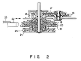
- the gear 18 is coaxially arranged with a first gear 19 of a clutch gear mechanism 18a.
- the first gear 19 is stacked on a second gear 21 through a friction member 20.
- a clutch switching gear 22 is opposed to the first and second gears 19 and 21 so as to be freely brought into contact therewith and separated therefrom.
- the gear 22 is pivotally mounted through a switching lever 23 which is interlocked with an operation mode switching mechanism, and is selectively meshed with the first and second gears 19 and 21 in response to the operation mode.
- a pulley 24 is coaxially arranged with the second gear 21.
- One end of a drive belt 25 is looped around the pulley 24, and the other end of the belt 25 is looped around a drive pulley 26 (see Fig. 1B).
- the drive pulley 26 is fitted on the rotating shaft of a driving capstan motor 27.
- a capstan 28 is coaxially mounted on the capstan motor 27.
- a tape t is to be urged against the capstan 28 through a pinch roller P.
- the driving force of the motor 27 is transmitted to the pulley 24 through the drive belt 25 and is subsequently transmitted to the second gear 21.
- a drive gear 29 is fitted around a rotating body of the capstan motor 27.
- a lifting gear 30 is opposed to the drive gear 29.
- the lifting gear 30 is arranged to be freely moved, through a spring mechanism (not shown), in the axial direction with respect to the main chassis 10.
- One end of a pivotal switching lever 31 is engaged with the upper surface of the lifting gear 30 (see Fig. 3).
- the other end of the switching lever 31 is engaged with a first cam portion formed on one surface of a mode switching cam 32 of the operation mode switching mechanism.
- the pivotal movement of the switching lever 31 is controlled through the mode switching cam 32 in such a manner that one end of the switching lever 31 is separated from the lifting gear 30 in a cassette loading state so as to cause the lifting gear 30 to move upward through the spring mechanism (not shown) and to be meshed with the drive gear 29, and, in a state in which cassette loading is completed, one end of the switching lever 31 causes the lifting gear 30 to move downward against the biasing force of the spring mechanism (not shown) to be separated from the drive gear 29.
- a pulley 33 is coaxially arranged on the lifting gear 30.
- One end of a drive belt 34 is looped around the pulley 33.
- the other end of the drive belt 34 is looped around a pulley 35.
- the pulley 35 is coaxially arranged with a worm 36 (see Fig. 1A) of the loading drive mechanism 13 .
- the rotational force of the capstan motor 27 is selectively transmitted to the pulley 33, the drive belt 34, the pulley 35, and the worm 36 in accordance with the vertical movement of the lifting gear 30, thereby controlling the driving operation of the loading drive mechanism 13 and moving the cassette holder 12 in the above-described manner.
- a helical scan type cylinder 37 on which magnetic heads are mounted is arranged on the main chassis 10 so as to correspond to the frame 11 and to be obliquely rotatable with respect to the main chassis 10.
- first and second guide grooves 38a and 38b are formed around the cylinder 37 on the main chassis 10 so as to oppose the tape inlet and outlet sides, respectively.
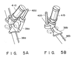
- first and second tape extract members 39a and 39b are movably housed in the first and second guide grooves 38a and 38b.
- inclined posts 40a and 40b which are substantially parallel to the cylinder 37 and guide rollers 41a and 41b which are substantially perpendicular to the rotating support surface of the cylinder 37, i.e., the main chassis 10 are respectively mounted on the first and second tape extract members 39a and 39b so as to be abreast with each other.
- the inclined posts 40a and 40b, and the guide rollers 41a and 41b are formed upright on base portions mounted on the main chassis 10.
- Two pairs of columnar projections 39a1 and 39a2, and 39bl and 39b2 which vertically extend from the base portions through the guide grooves 38a and 38b, respectively, are arranged on the tape extract members 39a and 39b, respectively at predetermined intervals.
- each of the projections 39al to 39b2 is set to be slightly smaller than the width of each of the guide grooves 38a and 38b so as to prevent backlash and to be movable. This determines the postures of the tape extract members 39a and 39b of the main chassis 10 in the horizontal direction.
- projection pieces 39a3 and 39b3 whose widths are slightly larger than those of the guide grooves 38a and 38b are formed on the tape extract members 39a and 39b so as to clamp the main chassis 10 from its upper and lower surfaces, thereby preventing backlash of the tape extract members 39a and 39b in the vertical direction.
- Lock portions 39a4 and 39b4 are formed on the tape extract members 39a and 39b.
- the lock portions 39a4 and 39b4 are respectively brought into contact with hold members 47a and 47b so as to position the tape extract members 39a and 39b when they move to tape loading end positions.
- the curvatures of the first and second guide grooves 38a and 38b are set in relation to the positions of the inclined posts 40a and 40b, the guide rollers 41a and 41b, and the projections 39a1 to 39b2 of the tape extract members 39a and 39b in such a manner that the guide rollers 41a and 41b of the tape extract members 39a and 39b are respectively moved from positions Y1 near positions X as loading start positions to positions Y2 near positions Z as loading end positions so as to lead the inclined posts 40a and 40b.
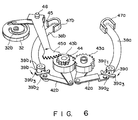
- first and second link mechanisms 42a and 42b One end of each of first and second link mechanisms 42a and 42b is coupled to a corresponding base portion of the first and second tape extract members 39a and 39b, as shown in Fig. 6.
- the other end of each of the first and second link mechanisms 42a and 42b is supported by a corresponding one of first and second drive gears 43a and 43b which are meshed with each other.
- a notched gear 44 is coaxially arranged on the second drive gear 43b.
- a fan-like gear 45a which is formed on one end of a drive lever 45 is meshed with the notched gear 44.
- the intermediate portion of the drive lever 45 is pivotally supported on the main chassis 10 through a pivot shaft 46, and the other end thereof is engaged with a second cam surface 32b of the mode switching cam 32.
- the drive lever 45 is controlled upon interlocking with the mode switching cam 32, which is driven by a tape loading motor (not shown), so as to drive the first and second tape extract members 39a and 39b through the first and second drive gears 43a and 43b, the notched gear 44, and the first and second link mechanisms 42a and 42b, thereby performing tape loading.
- the guide rollers 41a and 41b of the first and second tape extract members 39a and 39b are respectively guided by the first and second guide grooves 38a and 38b so as to lead the inclined posts 40a and 40b, thereby winding the tape t around the cylinder 37.
- the first and second guide grooves 38a and 38b are formed around the cylinder 37 so as to guide the first and second tape extract members 39a and 39b in such a manner that the guide rollers 41a and 41b are caused to lead the inclined posts 40a and 40b.
- tape loading and unloading are performed by driving the first and second tape extract members 39a and 39b along the first and second guide grooves 38a and 38b, respectively.
- the tape t is extracted from the tape cassette C by the first and second tape extract members 39a and 39b, and tape loading is performed while the tape t is supported by the guide rollers 41a and 41b, which are guided to lead the inclined posts 40a and 40b, and the cylinder 37, portions of the tape which are inclined by the cylinder 37 are corrected by the guide rollers 41a and 41b.
- the movement of the tape t in the axial direction is restricted as tape loading proceeds, and tape loading is accurately and smoothly performed while the tape is reliably supported at a normal position between the flanges of the guide rollers 41a and 41b. This prevents damage to the tape t , and hence high-precision tape pass is reliably performed.
- a tape loading apparatus which can perform an accurate, smooth tape loading operation with a simple arrangement.
Landscapes
- Replacement Of Web Rolls (AREA)
- Folding Of Thin Sheet-Like Materials, Special Discharging Devices, And Others (AREA)
Applications Claiming Priority (2)
| Application Number | Priority Date | Filing Date | Title |
|---|---|---|---|
| JP63333614A JPH02177157A (ja) | 1988-12-28 | 1988-12-28 | テープローディング装置 |
| JP333614/88 | 1988-12-28 |
Publications (2)
| Publication Number | Publication Date |
|---|---|
| EP0376267A2 true EP0376267A2 (de) | 1990-07-04 |
| EP0376267A3 EP0376267A3 (de) | 1991-10-09 |
Family
ID=18268020
Family Applications (1)
| Application Number | Title | Priority Date | Filing Date |
|---|---|---|---|
| EP19890123983 Withdrawn EP0376267A3 (de) | 1988-12-28 | 1989-12-27 | Schrägspurbandladegerät mit Bandtorsionsschutz |
Country Status (3)
| Country | Link |
|---|---|
| EP (1) | EP0376267A3 (de) |
| JP (1) | JPH02177157A (de) |
| KR (1) | KR930009655B1 (de) |
Families Citing this family (3)
| Publication number | Priority date | Publication date | Assignee | Title |
|---|---|---|---|---|
| US6703707B1 (en) | 1999-11-24 | 2004-03-09 | Denso Corporation | Semiconductor device having radiation structure |
| KR100424576B1 (ko) * | 2001-10-20 | 2004-03-27 | 엘지전자 주식회사 | 자기기록재생기의 슬랜트베이스 가이드구조 |
| CN115709673A (zh) | 2021-08-23 | 2023-02-24 | 明门瑞士股份有限公司 | 安全座椅 |
Family Cites Families (8)
| Publication number | Priority date | Publication date | Assignee | Title |
|---|---|---|---|---|
| JPS52134410A (en) * | 1976-05-04 | 1977-11-10 | Matsushita Electric Ind Co Ltd | Rotary head tape magnetic record/reproduce device |
| JPS5827580B2 (ja) * | 1976-05-04 | 1983-06-10 | 松下電器産業株式会社 | 磁気記録再生装置 |
| US4258399A (en) * | 1978-02-15 | 1981-03-24 | Hitachi, Ltd. | Magnetic recording and reproducing apparatus |
| FR2477748B1 (fr) * | 1980-03-07 | 1987-10-30 | Victor Company Of Japan | Dispositif de mise en place d'une bande magnetique dans des appareils d'enregistrement et/ou de lecture |
| DE3127592A1 (de) * | 1980-07-14 | 1982-04-01 | Canon K.K., Tokyo | Kassettengeraet fuer magnetische aufnahme und/oder wiedergabe |
| JPS6085753U (ja) * | 1983-11-18 | 1985-06-13 | 日本ビクター株式会社 | 磁気テ−プ記録再生装置 |
| JPS60163538U (ja) * | 1984-04-04 | 1985-10-30 | 三洋電機株式会社 | テ−プロ−デイング機構 |
| JPS6340841U (de) * | 1986-08-30 | 1988-03-17 |
-
1988
- 1988-12-28 JP JP63333614A patent/JPH02177157A/ja active Pending
-
1989
- 1989-12-27 EP EP19890123983 patent/EP0376267A3/de not_active Withdrawn
- 1989-12-28 KR KR1019890019781A patent/KR930009655B1/ko not_active Expired - Fee Related
Also Published As
| Publication number | Publication date |
|---|---|
| KR900010717A (ko) | 1990-07-09 |
| JPH02177157A (ja) | 1990-07-10 |
| EP0376267A3 (de) | 1991-10-09 |
| KR930009655B1 (ko) | 1993-10-08 |
Similar Documents
| Publication | Publication Date | Title |
|---|---|---|
| EP0127447B1 (de) | Magnetbandladegerät | |
| EP0442525B1 (de) | Magnetisches Aufzeichnungs- und Wiedergabegerät | |
| US5374003A (en) | Tape threading system for a helical tape drive | |
| US6157512A (en) | Recording and/or reproducing apparatus including tape loading mechanism with speed control of tape loading guides | |
| US6325264B1 (en) | Video cassette recorder | |
| EP0376280A1 (de) | Riemenangetriebenes Bandlaufwerk mit Rückschlagschutz | |
| EP0630013B1 (de) | Bandladevorrichtung von Magnetaufzeichnungs-/Wiedergabegerät | |
| US5568339A (en) | Recording and/or reproducing device operable with a plurality of different size cassettes | |
| KR930009655B1 (ko) | 테이프 비틀림 방지기능을 가진 헬리컬스캔 타입 테이프 로딩장치 | |
| US5196971A (en) | Tape loading mechanism for use in magnetic recording/reproducing apparatus having tape control features for preventing damage to tape | |
| EP0422670B1 (de) | Bandladevorrichtung für Videobandaufzeichnungsgerät | |
| EP0376242A2 (de) | Kassettenlademechanismus für ein Aufnahme-/Wiedergabegerät | |
| JP3059319B2 (ja) | テープローディング機構 | |
| JP3057288B2 (ja) | テープローディング機構 | |
| JP2771747B2 (ja) | テープローディング機構 | |
| KR0128986Y1 (ko) | 비디오 테이프 레코더의 카세트 로딩장치 | |
| JP2948997B2 (ja) | 磁気記録再生装置のスライド機構 | |
| KR0141189B1 (ko) | 핀치롤러 승강장치 | |
| JP2569154B2 (ja) | 磁気記録再生装置のテープ案内機構 | |
| JPS61233455A (ja) | テ−プロ−デイング装置 | |
| JPH0610909B2 (ja) | テ−プロ−デイング装置 | |
| JPH01140454A (ja) | 磁気記録再生装置のローディング装置 | |
| JPH0721638A (ja) | テープローディング機構 | |
| JPH06290520A (ja) | 磁気記録再生装置 | |
| JPS62271243A (ja) | 磁気記録再生装置 |
Legal Events
| Date | Code | Title | Description |
|---|---|---|---|
| PUAI | Public reference made under article 153(3) epc to a published international application that has entered the european phase |
Free format text: ORIGINAL CODE: 0009012 |
|
| 17P | Request for examination filed |
Effective date: 19900124 |
|
| AK | Designated contracting states |
Kind code of ref document: A2 Designated state(s): DE FR GB |
|
| PUAL | Search report despatched |
Free format text: ORIGINAL CODE: 0009013 |
|
| AK | Designated contracting states |
Kind code of ref document: A3 Designated state(s): DE FR GB |
|
| 17Q | First examination report despatched |
Effective date: 19930407 |
|
| STAA | Information on the status of an ep patent application or granted ep patent |
Free format text: STATUS: THE APPLICATION IS DEEMED TO BE WITHDRAWN |
|
| 18D | Application deemed to be withdrawn |
Effective date: 19930818 |