EP0376342B1 - Dispositif de traitement de données pour instrument de musique électronique - Google Patents
Dispositif de traitement de données pour instrument de musique électronique Download PDFInfo
- Publication number
- EP0376342B1 EP0376342B1 EP89124128A EP89124128A EP0376342B1 EP 0376342 B1 EP0376342 B1 EP 0376342B1 EP 89124128 A EP89124128 A EP 89124128A EP 89124128 A EP89124128 A EP 89124128A EP 0376342 B1 EP0376342 B1 EP 0376342B1
- Authority
- EP
- European Patent Office
- Prior art keywords
- data
- tone
- program
- storage means
- envelope
- Prior art date
- Legal status (The legal status is an assumption and is not a legal conclusion. Google has not performed a legal analysis and makes no representation as to the accuracy of the status listed.)
- Expired - Lifetime
Links
Images


Classifications
-
- G—PHYSICS
- G10—MUSICAL INSTRUMENTS; ACOUSTICS
- G10H—ELECTROPHONIC MUSICAL INSTRUMENTS; INSTRUMENTS IN WHICH THE TONES ARE GENERATED BY ELECTROMECHANICAL MEANS OR ELECTRONIC GENERATORS, OR IN WHICH THE TONES ARE SYNTHESISED FROM A DATA STORE
- G10H7/00—Instruments in which the tones are synthesised from a data store, e.g. computer organs
- G10H7/02—Instruments in which the tones are synthesised from a data store, e.g. computer organs in which amplitudes at successive sample points of a tone waveform are stored in one or more memories
- G10H7/04—Instruments in which the tones are synthesised from a data store, e.g. computer organs in which amplitudes at successive sample points of a tone waveform are stored in one or more memories in which amplitudes are read at varying rates, e.g. according to pitch
-
- G—PHYSICS
- G10—MUSICAL INSTRUMENTS; ACOUSTICS
- G10H—ELECTROPHONIC MUSICAL INSTRUMENTS; INSTRUMENTS IN WHICH THE TONES ARE GENERATED BY ELECTROMECHANICAL MEANS OR ELECTRONIC GENERATORS, OR IN WHICH THE TONES ARE SYNTHESISED FROM A DATA STORE
- G10H1/00—Details of electrophonic musical instruments
- G10H1/02—Means for controlling the tone frequencies, e.g. attack or decay; Means for producing special musical effects, e.g. vibratos or glissandos
- G10H1/04—Means for controlling the tone frequencies, e.g. attack or decay; Means for producing special musical effects, e.g. vibratos or glissandos by additional modulation
- G10H1/053—Means for controlling the tone frequencies, e.g. attack or decay; Means for producing special musical effects, e.g. vibratos or glissandos by additional modulation during execution only
- G10H1/057—Means for controlling the tone frequencies, e.g. attack or decay; Means for producing special musical effects, e.g. vibratos or glissandos by additional modulation during execution only by envelope-forming circuits
- G10H1/0575—Means for controlling the tone frequencies, e.g. attack or decay; Means for producing special musical effects, e.g. vibratos or glissandos by additional modulation during execution only by envelope-forming circuits using a data store from which the envelope is synthesized
-
- G—PHYSICS
- G10—MUSICAL INSTRUMENTS; ACOUSTICS
- G10H—ELECTROPHONIC MUSICAL INSTRUMENTS; INSTRUMENTS IN WHICH THE TONES ARE GENERATED BY ELECTROMECHANICAL MEANS OR ELECTRONIC GENERATORS, OR IN WHICH THE TONES ARE SYNTHESISED FROM A DATA STORE
- G10H1/00—Details of electrophonic musical instruments
- G10H1/18—Selecting circuits
- G10H1/183—Channel-assigning means for polyphonic instruments
- G10H1/185—Channel-assigning means for polyphonic instruments associated with key multiplexing
- G10H1/186—Microprocessor-controlled keyboard and assigning means
-
- G—PHYSICS
- G10—MUSICAL INSTRUMENTS; ACOUSTICS
- G10H—ELECTROPHONIC MUSICAL INSTRUMENTS; INSTRUMENTS IN WHICH THE TONES ARE GENERATED BY ELECTROMECHANICAL MEANS OR ELECTRONIC GENERATORS, OR IN WHICH THE TONES ARE SYNTHESISED FROM A DATA STORE
- G10H5/00—Instruments in which the tones are generated by means of electronic generators
-
- G—PHYSICS
- G10—MUSICAL INSTRUMENTS; ACOUSTICS
- G10H—ELECTROPHONIC MUSICAL INSTRUMENTS; INSTRUMENTS IN WHICH THE TONES ARE GENERATED BY ELECTROMECHANICAL MEANS OR ELECTRONIC GENERATORS, OR IN WHICH THE TONES ARE SYNTHESISED FROM A DATA STORE
- G10H7/00—Instruments in which the tones are synthesised from a data store, e.g. computer organs
- G10H7/08—Instruments in which the tones are synthesised from a data store, e.g. computer organs by calculating functions or polynomial approximations to evaluate amplitudes at successive sample points of a tone waveform
-
- G—PHYSICS
- G10—MUSICAL INSTRUMENTS; ACOUSTICS
- G10H—ELECTROPHONIC MUSICAL INSTRUMENTS; INSTRUMENTS IN WHICH THE TONES ARE GENERATED BY ELECTROMECHANICAL MEANS OR ELECTRONIC GENERATORS, OR IN WHICH THE TONES ARE SYNTHESISED FROM A DATA STORE
- G10H2250/00—Aspects of algorithms or signal processing methods without intrinsic musical character, yet specifically adapted for or used in electrophonic musical processing
- G10H2250/541—Details of musical waveform synthesis, i.e. audio waveshape processing from individual wavetable samples, independently of their origin or of the sound they represent
- G10H2250/621—Waveform interpolation
Definitions
- the present invention relates to a data processing apparatus for a sound signal generator, and, more particularly, to the architecture of a data processing apparatus for electronic musical instruments.
- the invention furthermore relates to an electronic musical instrument comprising such a data processing apparatus.
- a microcomputer merely processes control inputs to a musical instrument, such as an input from a keyboard or console panel, an input from a MIDI or other external units and an input from an internal or external unit, and sends proper commands to the sound source circuit.
- Sound source circuits which have different structures depending on the system for generating musical tones, normally have a large circuit scale irrespective of the structure of the sound source systems.
- the circuit scale of typical sound source circuits is about two times that of a microcomputer (central processing unit).
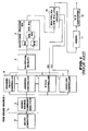
- Fig. 1 exemplifies in a block diagram of a sound source circuit involving a PCM sound source.
- a microcomputer 2 which controls a PCM sound source 1, sends data (command) necessary for tone generation to the PCM sound source 1.
- Such a command is set in individual sections in the sound source through a sound source command analyzer 3.
- data is set through the following procedures at the beginning of tone generation.
- the PCM sound source 1 produces a musical tone in the following manner.
- the address controller 5 reads out from the waveform memory 8 waveform data located at two adjacent addresses closest to an accumulated result of the pitch data from the pitch controller 6, the waveform data representing an immediately preceding waveform value and an immediately following waveform value.
- the waveform data is sent to a waveform processor 9 which in turn computes the difference between these two waveform values.
- the difference and the immediately preceding waveform value are sent to a multiplier 10, which multiplies the computed difference by a decimal point portion PD of the address of the waveform memory (given from the pitch controller 6 in the diagram) and adds the immediately preceding waveform value to the resultant value to thereby provide an interpolation value.
- the multiplier 10 then multiplies this interpolation value by an envelope value ED produced in the envelope controller 7, thus providing an instantaneous value of a tone waveform of the channel.
- This instantaneous value is accumulated by an adder 11 for all the channels, and the resultant data is sent to a D/A converter 12 to be an analog tone signal.
- a specific sound source circuit has a structure to simply realize a specific sound source system and one or combination of a specific number of polyphonic sounds, so that changing the polyphonic number necessitates great alteration of the circuit and/or addition of a circuit. It is also necessary to design a set of commands to be sent to the sound source circuit from the microcomputer in accordance with the sound source, thus requiring a significant time for developing a sound source control program.
- controllers for an electronic musical instrument whose architecture permits a microcomputer alone to simultaneously execute processing of control inputs to a musical instrument and tone generation.
- a microcomputer having an architecture to ensure tone generation that requires a high-speed data processing of a vast amount of data.
- typical microcomputers use an internal register or a general-purpose internal register, called an accumulator, as memory means for temporary storage of computing data.
- the accumulator may hold data from a data memory on one occasion, and holds the result of computation (e.g., addition) of two pieces of data from the data memory performed by a computing circuit on another occasion. Data temporarily held in the accumulator is set back to the memory location specified on the data memory.
- Using a microcomputer with such a structure for tone generation requires a considerable time for frequent data transfer between the data memory and the accumulator (or general-purpose register) and thus becomes a hindrance to achieving tone generation processing that should deal with a vast amount of data.
- FIG. 2 illustrates a typical envelope controller.
- Various values from a microcomputer are set in an envelope ⁇ x register 24, an envelope ⁇ y register 25 and a target envelope register 26 via the sound source analyzer 3 which serves as an interface.
- the content of an envelope ⁇ x timer 21 is counted up by an INC counter 22.
- a comparator 23 outputs a coincidence signal to clear the INC counter 22.
- the coincidence signal further opens an AND gate G1, and data ⁇ y from the envelope ⁇ y register 25 is input to an adder-subtracter 27.
- This data ⁇ y is added to or subtracted from a present envelope value from a present envelope register 29 in accordance with an adding/subtracting flag (a specific bit of the envelope ⁇ y register 25).
- the result of the computation is compared with a target envelope level from a target envelope register 29 by a second comparator 28.
- the comparison result is used to determine a new present envelope value. In other words, if the computed result has not reached the target envelope, it is output as a new present envelope value via a gate G2 and set back to the register 29. If the computed result reaches the target envelope, however, the coincidence signal from the comparator 28 opens a gate G3 through an inverter INV to output the target envelope as a new present envelope value, which is then set back to the register 29.
- the coincidence signal from the comparator 28 is held in a coincidence signal holding circuit 30 to request setting of data of the next envelope step ( ⁇ x, ⁇ y, a target envelope).
- the envelope generator as shown in Fig. 2 has a shortcoming that it is part of the hardware of the sound source circuit. Once the microcomputer sets data of ⁇ x, ⁇ y and the target value, therefore, it cannot grasp a present envelope value thereafter. (Permitting the microcomputer to read out the present envelope value, though possible, requires a significantly complex circuit.) When it is necessary to jump the envelope step, therefore, it is difficult to set data ( ⁇ x, ⁇ y, the target value) suitable for the present envelope value. Assuming that data for a release envelope which consists of three segments is on the microcomputer side as shown in Fig. 3, due to the present envelope value unclear, the microcomputer cannot determine data ( ⁇ x, ⁇ y, the target value) to which segment should be sent to the sound source.
- a conventional solution to this problem is to send an envelope step update signal (the output of the coincidence signal holding circuit 30 in Fig. 2) to the microcomputer to request updating of the step and to transfer data for the next step to the sound source from the microcomputer.
- the microcomputer cannot grasp the present envelope value being produced by the sound source, it can grasp the envelope step being executed by the sound source.
- This permits the microcomputer to select a release envelope segment corresponding to a value which this envelope step can take at a tone release time, i.e., a release envelope segment having a target value lower than but closest to the target value of the present envelope, then transfer data for the selected release envelope segment to the sound source.
- This particular design has a problem that a zigzag line characteristic of a release envelope is restricted by another envelope portion. This is because that release envelope data should be prepared in advance to match with the range of the envelope value of another step, thus limiting the characteristic that the envelope can have.
- US-A 4,184,400 discloses a data processing apparatus according to the preamble of claim 1 as well as an electronic musical system which is provided with additional computer-external tone generator units generating the actual musical sound signals.
- the CPU determines control signals for the tone generator units.
- GB-A-2 013 386 discloses an electronic sound processing device in which the output signals of the control processor are fed to an output control system.
- the output control system generates the musical sound signals.
- the present invention provides a data processing apparatus which can extract a digital musical tone generated by a microcomputer itself at an accurate sampling period and output it as an analog signal with less distortion.
- the microcomputer comprises first latch means for latching a digital tone signal generated by the microcomputer at a timing of a program control signal from the microcomputer, and second latch means, provided between an output of the first latch means and D/A converting means, for latching an output signal of the first latch means at a timing of an accurate sampling time signal.
- a digital musical tone signal supplied to the input of the D/A converting means can be switched at a timing of an accurate sampling time signal by the function of the second latch means. This means that the conversion period for converting a digital signal into an analog signal in the D/A converting means is accurately maintained. Therefore, distortion on an analog musical tone signal which may occur during D/A conversion can be reduced as much as possible, so that an acoustic signal with a good quality can be output.
- the above apparatus requires no hardware of a sound source circuit for generating musical tones.
- the data processing apparatus for an electronic musical instrument having this novel architecture has significant advantages.
- the first advantage is freedom of design. More specifically, alteration of the number of polyphonic sounds and alteration of a tone combining system can be coped with design alteration of a program.
- the second advantage is its capability to significantly reduce the overall circuit scale because no sound source circuit hardware is needed. Conventionally, since a source circuit LSI chip has a large circuit scale, there is a limit to improving the yield in production of chips (the yield being substantially inversely proportional to the chip area). Those advantages can therefore considerably reduce the cost for manufacturing electronic musical instruments.
- the program storage means comprises a read only memory (ROM).
- the microcomputer is realized by an integrated circuit chip on which a D/A converter for converting a digital musical tone into an analog signal and a port for receiving an input to control the electronic musical instrument are mounted in addition to the aforementioned components of the microcomputer.
- the arithmetic operation means may include a multiplier for computing waveform data.
- the program for generating musical tones can be executed by interrupt program processing (interrupt processing) invoked by an interrupt signal which is generated in a tone sampling period.
- interrupt program processing interrupt processing
- the use of such a timer interrupt technique can ensure accurate tone generation.
- programs to be stored in the program storage means can be efficiently prepared and the total number of steps of each program can be reduced, thus requiring less memory capacity for the program storage means.
- generation of an interrupt signal at every given time can be utilized so that if a routine for measuring the elapse of time is incorporated in the interrupt program, it is possible to acquire time data necessary in a main program (main flow), such as a period with respect to the resolution of a tempo for an automatic musical performance or accompaniment.
- an envelope gently changes with time, so that its generation may not be executed in the interrupt process.
- the timing at which the envelope is updated can be known from the result of the time measuring process executed in the interrupt process while running the envelope producing process (if the envelope needs to be updated at a constant period).
- the microcomputer is realized by an integrated circuit chip on which a D/A converter for converting a digital musical tone data into an analog signal and a port for receiving an input to control the electronic musical instrument are mounted in addition to the aforementioned components of the microcomputer.
- the registers in the arithmetic operation storage means can serve as means to store data as well as a so-called accumulator. This can eliminate the need for an ordinary accumulator.
- the individual registers in the arithmetic operation storage means can be directly addressed by a program stored in the program storage means (which does not mean that it is not possible to execute indirect addressing such as the one done by an index). Accordingly, an arithmetic operation between the registers can be directly executed (without going through the accumulator) using the arithmetic operation means.
- the individual registers in the arithmetic operation storage means can be used exclusively; general use of the registers is also possible so that the "exclusive use” does not mean to deny the general use of part of the registers.
- the arithmetic operation storage means includes a group of registers which are used for arithmetic operation and for exclusively storing various musical tone parameters (such as an envelope rate, a phase value parameter and a phase change degree parameter). Running the tone generating program can ensure efficient execution of arithmetic operations (with the highest efficiency) between those registers exclusive for the various musical tone parameters in an operational sequence until digital data sample of a musical tone is obtained, thus reducing the number of times data in the tone data storage means is referred to.
- one register is exclusively used to hold the value of the present phase (phase of a waveform), while another register is exclusively used to hold data of the degree of a change in phase value.
- the tone generating program issues a command to add the degree of change to the present phase value. At that time, it is not particularly necessary to read out data of the present phase value and the degree of change from the tone data storage means or to store the envelope value resulting from the required arithmetic operation.
- the register (first register) for storing the present phase value is directly assigned as the first operand (item to be operated) and the register (second register) for storing the degree of change as the second operand (item to operate) and addition of these two values is specified by an operation code, then the data of the first register and the data of the second register are output and input to the arithmetic operation means where an adder performs the addition, and the output of this means (new phase value) is returned to the first register, all automatically, i.e., under the control of the operation control means.
- a group of registers for exclusive storage of data about the degree of change within the respective ranges and another group of registers (referred to as group B) for exclusive storage of the phases at the boundaries of the phase ranges (boundary value data) should be prepared and the boundary values in the register group B need to be compared with the present phase value prior to executing the phase addition. Based on the comparison result, the register storing the selected or desired degree of change is determined among the register group A.
- a musical tone is generated by a timer interrupt program in a second embodiment to be described later.
- ordinary microcomputers need to save the status of a process at that point of time in order to continue the process after the interrupt processing is completed.
- the tone generating program the program which has made the interrupt
- only an exclusive register is used to store musical tone parameters. This means that no data rewriting or updating is performed for those registers which are used by a program that has been interrupted, while the tone generating program is running.
- an input/output port for receiving control inputs to a musical instrument, a timer interrupt controller for causing an interrupt and a D/A converter for converting a digital data sample of a generated musical tone into an analog signal are also mounted on the IC chip containing the microcomputer.
- the arithmetic operation means includes a multiplier used for computing waveform data.
- the invention also provides a data processing apparatus for an electronic musical instrument which can generate a musical tone without using exclusive sound source circuit hardware and can produce an envelope whose characteristic is free of any restriction at an accurate timing.
- the microcomputer can always grasp the present envelope value which is originated from execution of a routine to compute the envelope of a musical tone. Accordingly, it is free to jump the steps of an envelope, thus totally eliminating any restriction to the characteristic of an envelope that can be generated.
- the present invention also provides an electronic musical instrument having a microcomputer without the need for exclusive sound source circuit hardware, as stated in claim 11.
- This electronic musical instrument can generate an envelope free of restriction on its characteristic at an accurate timing.
- the electronic musical instrument can have microcomputer that controls a tone generating program to generate a musical tone and can extract a digital musical tone at an accurate sampling period to thereby acquire an analog signal with less distortion.
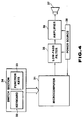
- Fig. 4 illustrates the general structure of an electronic musical instrument associated with the first embodiment.
- the general control of the apparatus is executed by a microcomputer 31.
- the microcomputer 31 executes not only processing of control inputs to a musical instrument but also a tone generation process, so that no sound source circuit hardware is required for tone generation.
- a switch section 34 comprising a keyboard 32 and function keys 33 serves as a source to enter control inputs to a musical instrument, and data entered via this switch section 34 is processed by the microcomputer 31.
- a digital tone signal generated by the microcomputer 31 is converted into an analog signal by a D/A converter (included within the microcomputer 31), filtered by a low-pass filter 35 and amplified by an amplifier 36 so that a musical sound is produced through a loudspeaker 37.
- a power source 38 serves to supply the necessary power to the microcomputer 31, low-pass filter 35 and amplifier 36.
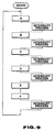
- Fig. 5 illustrates in a block diagram the internal structure of the microcomputer 31.
- the individual elements illustrated are mounted on one chip.
- the microcomputer 31 actually manufactured with a chip size of 5 mm ⁇ 5 mm is capable of generating eight polyphonic sounds simultaneously and is of a PCM (Pulse Code Modulation) type tone forming system.
- PCM Pulse Code Modulation
- the present invention can well apply to other microcomputers capable of generating a different number of polyphonic sounds and having a different tone forming system.
- a program for processing various control inputs to a musical instrument and a program for generating musical tones are stored in a control ROM 41, and program words (commands) located at addresses specified via a ROM address decoder 42 by a ROM address controller 49 are sequentially output.
- a program word has a length of 28 bits and part of the program word is input as a lower portion of the next address to be read out (address within a page) to the ROM address controller 49; this is a so-called next address system.
- a program counter system may also be employed.
- a RAM address controller 43 specifies the address of an associated register in a RAM 44.
- the operand may also serve to set a numerical value in the register.
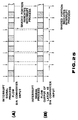
- the RAM 44 comprises registers which are used for general arithmetic operations, flag operations, arithmetic operations for musical tones, and so forth. As exemplified in Fig. 11, many registers are used exclusively for arithmetic operations for musical tones.
- a unit 45 serving as an adder-subtracter and logical operation section and a multiplier 46 constitute an arithmetic unit (AU), which is used when a command from the control ROM 42 is an arithmetic instruction.
- AU arithmetic unit
- the multiplier 46 is used for an arithmetic operation of a musical tone waveform, and first and second data inputs (e.g., 16-bit data) are multiplied and data having the same length as the inputs (i.e., 16 bits) is output in order to optimize the operation.
- first and second data inputs e.g., 16-bit data
- data having the same length as the inputs i.e., 16 bits
- a ROM 47 for control data and waveform stores various musical tone control parameters such as pitch data, envelope data (rate, level), and musical tone waveform data of a PCM type.
- the envelope data and tone waveform data are prepared for each timbre of a musical tone.
- the ROM 47 is accessed indirectly by referring to the contents of the register on the RAM 44 specified by the operand in a program stored in the control RAM 41.
- the ROM 47 is an internal memory and its operation is directly controlled by an operation controller 48 which controls the operation of the RAM 44, so that the time of accessing to the ROM 47 is the same as the time of accessing to the RAM 44.
- An operation analyzer (operation controller) 48 decodes an operation (OP) code of a command from the control ROM 41 and sends control signals to its individual units in order to execute the specified operation.
- a timer interrupt is employed in this embodiment. That is, an interrupt controller 50 having a timer (hardware counter) sends a control signal (interrupt request signal) to the ROM address controller 49. In response to this signal, the ROM address controller 49 saves (holds) the address of the next command of the main program and sets the head address of an interrupt program (subroutine) that generates a musical tone in place of the former address. Then, the interrupt program starts running. Since a return command is placed at the end of the interrupt program, the ROM address controller 49 sets the saved address again and the flow returns to the main program when this return command is decoded by the operation analyzer 48.
- interrupt controller 50 which causes the microcomputer 31 to stop a presently-executing task and requests a special process, is illustrated as an internal element of the microcomputer 31 (CPU) in the diagram, it is logically an external element (peripheral unit) of the microcomputer 31.
- the interrupt program includes a routine for computing the waveform of a musical tone on each channel as will be described later, the waveform and envelope can be generated in the interrupt period.
- An input port 51 and an output port 52 are used for scanning the keys of the keyboard 32 and the function keys 33.
- a digital musical tone generated in the interrupt program is converted by a D/A converter 53 into an analog signal which is then output.
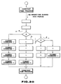
- Step A1 is an initializing process which clears the RAM (registers) 44 of the microcomputer 31 and sets the initial values of a rhythm tempo, etc. when power is turned on.
- step A2 the microcomputer 31 outputs a key scan signal from the output port 52, and fetches the status of the switch section 34 from the input port 51 to thereby set the statuses of the function keys 33 and keys on the keyboard in the key buffer area of the RAM 44.
- step A3 that function key whose status has changed is discriminated from the statuses of the function keys 33 acquired in step A2 and the previous statuses thereof, and the specified function is executed (e.g., setting of a tone number, an envelope number, a rhythm number, etc.).
- step A4 that key whose status has changed (being pressed or released) is discriminated from the newest statuses of the keys on the keyboard 32 acquired in step A2 and the previous key statuses.
- step A5 key assigning for the tone generation process A9 is executed in accordance with the processing result attained in step A4.
- step A6 when a "demo" play key included in the function keys 33 is pressed, "demo" play data (sequencer data) is sequentially read out from the ROM 47 and is processed to thereby execute a key assign process for the tone generation process A9.
- rhythm data when a rhythm start key is pressed, rhythm data is sequentially read out from the ROM 47 to perform key assigning for the tone generation process A9.
- a one flow cycle timer process A8 in order to know the timing of the necessary event in the main flow, an arithmetic operation is performed on the basis of the one flow cycle time to acquire the reference value for the envelope timer (arithmetic operation cycle of the envelope) and the reference value of a rhythm.
- the one flow cycle time is obtained by measuring the number of timer interrupts executed during one flow cycle; this measuring is performed in an interrupt timer process B3 to be described later.
- various arithmetic operations for actually generating musical sounds are executed based on the data set in steps A5, A6 and A7.
- the results of the operations are set in a sound source processing register (Fig. 11) in the RAM 44. For instance, when a key is de-pressed, the envelope ⁇ x of the attack portion and the envelope ⁇ y for the target envelope increment/decrement flag as parameters for envelope generation are computed or read out and set in the associated registers in Fig.
- Step A10 is a preparation process for a pass to the next main flow.
- the "NEW ON” status indicating a change to the key-de-pressed state obtained by the present pass is set during "ON Continuing" status
- the "NEW OFF" status indicating a change to a key-released state is changed during "OFF Continuing” status.
- Fig. 7 illustrates the flow of the interrupt program which executes tone generation.
- tone waveform data (accumulated waveform values for eight sounds) which has been produced in a sound source process B2 in the previous interrupting process is sent to the D/A converter 53.
- samples of a musical tone are given to the D/A converter 53 in a constant interval.
- the subsequent sound source process B2 is a key point in this embodiment; this processing is conventionally executed by sound source circuit hardware. (Its detailed description will be given later.)
- the content of a timer register located in the RAM 44) for measuring one flow cycle is incremented by "1" every time an interrupt, which occurs for every given time, passes this timer register.
- Fig. 8 gives a detailed illustration of the sound source process B2.
- RAM area see Fig. 11
- steps C2 to C9 for eight channels are sequentially executed.
- the waveform value of a musical tone on the channel is added to the data stored in this RAM area.
- Fig. 9 illustrates the flow of the operation of the first embodiment along the time.
- "A" through “F” are parts of the main program (Fig. 6), and an interruption (Fig. 7) is executed for each given time.
- the time chart of the operation is shown in Fig. 10. As illustrated, every time an interrupt occurs, a tone waveform signal is input to the D/A converter 53 and the corresponding analog signal is output therefrom.
- Fig. 12 presents a detailed illustration of one of the steps C2-C9 in Fig. 8 with respect to one of eight channels.
- the channel process mainly consists of an envelope process (D1 to D7) and a waveform process (D8 to D21).
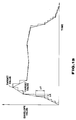
- Fig. 13 illustrates an envelope produced by the envelope process.
- the envelope of one musical tone consists of several steps (segments).
- ⁇ x represents an updating period of the envelope
- ⁇ y the degree of change in the envelope value.
- the envelope process (D1-D7) for each channel performs computation of updating the envelope for each updating time and checks if the step target level is reached. When the target level is reached, the target value is set in the present envelope register (see Fig. 11) and this event is detected in the tone generation process A9 of the main program. Then, envelope data for the next step ( ⁇ x, ⁇ y, the target envelope value) is set in the respective registers.
- step D1 The content of the timer register used for comparison with the computed period ⁇ x of the envelope is incremented for each occurrence of an interruption in step D1.
- the adding/subtracting flag (code bit) of the data ⁇ y a change in the envelope, is checked to see if the envelope is rising or falling in step D3.
- step D4 and D5 the present envelope is subjected to subtraction and addition, respectively.
- step D6 it is determined whether or not the present envelope has reached the target value. If the decision is affirmative, the target level is set to the present envelope. As a result, data of the next envelope step is set in the tone generation process A9 of the main program. If the read present envelope is zero in the process A9, it is treated as the end of tone generation.
- the microcomputer 31 can always grasp the status of the present envelope.
- an envelope is generated in the program-controlled envelope processes (D1-D7), the value of the present envelope is checked in the tone generation process A9 also controlled by the program, and a process according to the checking result is executed.
- This can eliminate the need for an envelope generator which is conventionally hardware, and can thus overcome the otherwise accompanying conventional problems.
- the reason why the program-controlled envelope process is executed particularly in the timer interrupt program will be discussed below referring to Figs. 14 and 15.
- Fig. 14 illustrates part of an envelope generated by a timer interrupt. Assuming that an envelope process is carried out in an ordinary subroutine, the result would be as shown in Fig. 15. If the subroutine for computing an envelope is placed in the main flow, the amount of work to be done varies and the time between subroutines for envelope computation also varies. This results in a change in time for measuring ⁇ x; the updating of time may come earlier on one occasion or may come late on another, so that the slope of the expected envelope cannot be accurately realized. If the envelope process is done in the timer interrupt process, the updating period ⁇ x can be kept constant due to the periodic occurrence of an interrupt, and the expected envelope can be obtained as shown in Fig. 14. Further, since the generated envelope is used in the waveform process within the same interrupting process, waveform generation can be effected in synchronism with changing the envelope.
- waveform data at two adjacent addresses are read out from the waveform ROM 47 using the integer portion of the present address, and the waveform value expected with respect to the present address indicated by (integer portion + decimal point portion) is attained through interpolation.
- the reason for requiring the interpolation is that the interrupt-initiated waveform sampling period is constant and the value of added addresses (pitch data) lies in a certain tone range in view of application to a musical instrument (with a musical instrument which produces only notes, if waveform data is prepared for each note, no interpolation is necessary with an unallowable increase in memory capacity, though).
- pitch data associated with this key, and the waveform start address, waveform end address and waveform loop address of the selected timbre are set in the respective registers of the RAM 44, namely, added address register, start address/present address register, end address register and loop address register.
- Fig. 17 illustrates one example of interpolation waveform data with respect to time.
- white marks indicate waveform data values located at addresses of the waveform ROM, and black marks interpolation values.
- step D8 the present address is added with the added address value to provide a new present address.
- the present address is compared with the end address in step D9. If the present address > the end address, the physical (address) or logical (operational) next address is computed through steps D10 and D11. If the present address ⁇ the end address, the next address is computed through a step D12.
- step D14 the waveform ROM is accessed using the integer portion of the address to acquire the next waveform data.
- the loop address is the address next to the end address from an operational point of view. In the case of Fig.
- the illustrated waveform data is read out repeatedly.
- the waveform data at the loop address as the next address is read out (D13).
- the waveform ROM is accessed using the integer portion of the present address to read out the present waveform data.
- the present waveform value is subtracted from the next waveform value, and the difference is multiplied by the decimal point portion of the present address in step D18.
- the result is added to the present waveform value in step D19 to thereby obtain linear interpolation value of the waveform.
- the linearly-interpolated data is multiplied by the present envelope value to obtain a tone data value of the channel (D20), and the obtained value is added to the content of the waveform adding register to accumulate tone data (D21).
- the control ROM has a size of 112 K bits, RAM 44 5.4 K bits and the control data/waveform ROM 47 (for 100 timbres) 508 K bits; one machine cycle is about 276 nanoseconds with a maximum number of cycles of the interrupt program when invoked being about 150; and the executing period of the interrupting process (tone output sampling period) is about 47 microseconds.
- the microcomputer 31 since the microcomputer 31 performs tone generation under the control of the timer interrupt program, sound source circuit hardware which is essential in the prior art is not necessary, thus resulting in reduction in circuit scale, improvement of the yield, reduction in manufacturing cost and high design freedom. Further, since a process for computing the waveform of a musical tone and a process for computing the envelope of the musical tone are executed by the timer interrupt program which is invoked by an interrupt signal that is accurately issued from the interrupt controller 50 at every tone sampling time, an envelope with the desired characteristic can accurately be generated.
- the microcomputer may be simply replaced with computer means or processing means for the mentioned operations.
- a timer interrupt is issued to output a tone waveform sample for each given time and a musical tone is generated by running an interrupt program.
- a dummy command (NOP command) is set in a program to execute the process in place of the interrupting process at each constant interval of time; this processing will be hereinafter called constant time process.
- NOP command a dummy command
- constant time process Since the time for executing each command of a program is determined by a master clock, a constant time processing program for generating a musical tone during that part of the main program which corresponds to the constant time (see Fig. 18) is inserted as a subroutine.
- Fig. 21 illustrates an example of the above case where a dummy command is put in tone generation process in constant time process.
- the interval T in which an interrupt signal is generated is very stable. This is because that the interrupt signal is produced by a hardware counter in an interrupt controller 50.
- the stability of the signal generation is determined by the stability of a clock generator (typically, a crystal oscillator) though not illustrated.
- the main process is interrupted by this interrupt signal and tone generation process (interrupting process) is executed during the interruption so as to keep the tone generation sampling period constant.
- tone generation process interrupting process
- this technical approach can set the averaged, tone generation sampling period equal to the interrupt signal generation interval T. Nevertheless, the timing at which the interrupting process actually starts may vary as emphasized in Fig. 22. This variation is originated in the program-controlled operation.
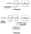
- the microcomputer 31 cannot immediately stop the presently-executing operation, so that the interrupting process starts upon termination of that operation. If the microcomputer 31 is in a process whose interruption is not desirable, the interruption is held until a sequence of operations for this process is completed. Transition to an interrupting process depends on the process which is being performed upon occurrence of an interrupt, so that the tone generation period inevitably becomes unstable. Specifically, the timing of the process executed in step B1 in Fig. 7, i.e., fetching digital tone data from the waveform adding register in the RAM 44 and setting it at the input port of the D/A converter 53, is shifted forward or backward. If the sampling period of the D/A converter 53 is the same as the executing interval of the step B1, a significant distortion would be caused on the signal during D/A conversion. This shortcoming is solved by the third embodiment.
- Fig. 23 illustrates the structure which sets the sampling period of tone generation equal to the conversion period of the D/A converter 53. More specifically, a software-controlled latch 55 is provided as a port of the D/A converter 53, and this latch 55 is controlled by a program control signal from the operation analyzer 48 to supply the output of the latch 55 to a control gate of an associated bit switch in a block 53A (not illustrated; typically, a current-controlled type electronic switch). As the block 53A actually converts a digital signal into an analog signal, it will be called D/A converter hereinafter. In the case of Fig.
- the waveform adding register in the RAM 44 is specified under the control of the operation analyzer 48 while the step B1 in the interrupt program, and newest digital tone data to be stored in the register is fetched on a data bus.
- a program control signal for strobe is supplied to a clock input of the latch 55 from the operation analyzer 48 at a timing where the digital tone data is on the data bus. Then, the data on the data bus is set, and new digital tone data is input to the D/A converter 53A from the latch 55. As shown in Fig. 25A, therefore, digital tone data to be input to the D/A converter 53A is switched at an unstable period due to the program control involved.
- the conversion period (sampling period) of the D/A converter 53A is not significantly stable, large distortion occurs in the converted signal during the conversion.
- the machine cycle of the microcomputer 31 being several tens of nanoseconds or several hundreds of nanoseconds, even a delay of one machine cycle significantly hinders the necessary accuracy of the conversion period for converting a digital signal of an audio-frequency into an analog signal with high fidelity.
- even deviation of the order of nanoseconds causes such distortion that can be audibly sensed by a person.
- An interrupt-controlled latch 56 which is controlled by an interrupt signal or accurate timing signal from the interrupt controller 50, is provided between the software-controlled latch 55 controllable by a program control signal from the operation analyzer 48 and the D/A converter 53A.
- the output of the latch 56 is switched in synchronism with the timing of the interrupt signal. That is, the interrupt signal generating period is the conversion (sampling) period of the D/A converter 53A.
- Fig. 25B illustrates a time chart for the structure shown in Fig. 24.
- the latch 56 which functions by the interrupt signal permits the timing for switching the input data of the D/A converter 53A to be synchronized with the interrupt signal. Because of the presence of the latch 56, the digital tone signal input to the D/A converter 53A is delayed by one period of the interrupt signal on the average. This delay, however, is quite insignificant. For instance, the period of the interrupt signal is 47 microseconds, and such a short period of time cannot be audibly sensed by people. In general, the order of several milliseconds is the audible limit for human beings.
- a waveform generating process is executed by a microcomputer in the above-described embodiments, it may be carried out by a minicomputer.
- the present invention can be worked out irrespective of the size of a computer or a processing system involved, as long as the computer or processor functions under software control.
Landscapes
- Engineering & Computer Science (AREA)
- Physics & Mathematics (AREA)
- Multimedia (AREA)
- Acoustics & Sound (AREA)
- General Engineering & Computer Science (AREA)
- Algebra (AREA)
- General Physics & Mathematics (AREA)
- Mathematical Analysis (AREA)
- Mathematical Optimization (AREA)
- Mathematical Physics (AREA)
- Pure & Applied Mathematics (AREA)
- Microelectronics & Electronic Packaging (AREA)
- Computer Hardware Design (AREA)
- Electrophonic Musical Instruments (AREA)
Claims (11)
- Appareil de traitement de données pour un générateur de signal sonore, comprenant un moyen de calculateur ou de processeur (31), ledit moyen de calculateur ou de processeur comprenant :
un moyen de stockage de programme (41) pour stocker un programme pour générer un ou plusieurs signaux sonores ;
un moyen de commande d'adresse (42, 49) pour commander une adresse dudit moyen de stockage de programme ;
un moyen de stockage de données de tonalité (47) pour stocker des données de tonalité nécessaires à la génération desdits signaux sonores ;
un moyen d'opération arithmétique (45, 46) pour calculer un ou plusieurs signaux sonores conformément aux données de tonalité stockées dans ledit moyen de stockage de données de tonalité ; et
un moyen de commande de fonctionnement (48) pour décoder chaque commande dudit programme stocké dans ledit moyen de stockage de programme et pour commander le fonctionnement dudit moyen de commande d'adresse, dudit moyen de stockage de données de tonalité et dudit moyen d'opération arithmétique, de telle sorte qu'un ou plusieurs signaux sonores puissent être générés en exécutant ledit programme contenu dans ledit moyen de stockage de programme,
caractérisé par un premier moyen de verrouillage (55) pour verrouiller ledit un ou lesdits plusieurs signaux sonores générés par ledit moyen de calculateur ou de processeur (31) en réponse à un signal de commande de programme provenant dudit moyen de calculateur ou de processeur (31) ;
un second moyen de verrouillage (56) pour verrouiller un signal de sortie dudit premier moyen de verrouillage selon un cadencement d'un signal de cadencement d'échantillonnage précis. - Appareil de traitement de données selon la revendication 1, dans lequel ledit moyen de stockage de données de tonalité (47) stocke des données de hauteur de son, des données d'enveloppe et des données de forme d'onde de son d'un type MIC en tant que dites données de tonalité.
- Appareil de traitement de données selon la revendication 1 ou 2, dans lequel ledit moyen de calculateur ou de processeur (31) comprend une puce de circuit intégré munie d'un convertisseur numérique/analogique pour convertir un signal sonore numérique en un signal analogique et d'un port pour recevoir une entrée dudit générateur de signal sonore.
- Appareil de traitement de données selon la revendication 1, 2 ou 3, dans lequel ledit moyen d'opération arithmétique (45, 46) inclut un multiplieur (46) pour calculer lesdits signaux sonores.
- Appareil de traitement de données selon l'une quelconque des revendications précédentes, dans lequel ledit moyen d'opération arithmétique (45, 46) inclut un moyen d'interpolation pour interpoler une valeur de forme d'onde attendue en relation avec une adresse située entre deux adresses adjacentes dudit moyen de stockage de données de tonalité (47).
- Appareil de traitement de données selon la revendication 5, dans lequel ledit moyen d'opération arithmétique (45, 46) lit les données de forme d'onde sonore selon une fréquence supérieure à la fréquence d'échantillonnage d'enregistrement du son original provenant du moyen de stockage de données de tonalité.
- Appareil de traitement de données selon l'une quelconque des revendications précédentes, dans lequel ladite entrée dudit générateur de signal sonore inclut une entrée par touches désignant une hauteur de son desdits signaux sonores qui doivent être générés, une entrée depuis un tableau de commande dudit générateur de signal sonore, une entrée de données de morceau de musique automatique et une entrée pour activer une unité externe.
- Appareil de traitement de données selon l'une quelconque des revendications précédentes, comprenant en outre un moyen de commande d'interruption de minuterie (50) pour générer un signal d'interruption pendant une période d'échantillonnage de tonalité musicale et ainsi, ledit programme permettant de générer un ou plusieurs signaux sonores est recherché dans ledit moyen de stockage de programme par ledit moyen de commande d'adresse qui reçoit ledit signal d'interruption provenant dudit moyen de commande d'interruption de minuterie et une génération desdits signaux sonores est effectuée en exécutant ledit programme recherché.
- Appareil de traitement de données selon l'une quelconque des revendications précédentes, comprenant en outre un moyen de stockage d'opération arithmétique (44) comprenant un certain nombre de registres directement adressables par ledit programme contenu dans ledit moyen de stockage de programme, lesdits registres incluant ceux qui sont utilisés pour une opération arithmétique lors de l'exécution dudit programme pour la génération d'un ou de plusieurs signaux sonores et bloquant exclusivement lesdites données de tonalité,
dans lequel :
ledit moyen d'opération arithmétique (45, 46) exécute des opérations arithmétiques entre lesdits registres dudit moyen de stockage d'opération arithmétique ;
ledit moyen de stockage de données de tonalité est adressable indirectement par l'intermédiaire desdits registres dudit moyen de stockage d'opération arithmétique par ledit programme contenu dans ledit moyen de stockage de programme ; et
ledit moyen de commande d'opération (48) commande en outre le fonctionnement dudit moyen de stockage d'opération arithmétique, lesdits registres dudit moyen de stockage d'opération arithmétique (44) étant utilises pour une opération arithmétique et pour stocker exclusivement lesdites données de tonalité en exécutant lesdits programmes de génération d'une tonalité musicale. - Appareil de traitement de données selon la revendication 8, dans lequel ledit programme qui doit être recherché et exécuté en réponse audit signal d'interruption inclut un sous-programme permettant de calculer une pluralité de signaux de tonalité et un sous-programme permettant de calculer une pluralité d'enveloppes desdits signaux de tonalité musicale, et une génération desdits signaux de tonalité musicale est exécutée sensiblement en synchronisation avec la génération desdites enveloppes desdits signaux de tonalité musicale et ainsi, ladite pluralité de signaux sonores sont générés en multipliant respectivement ladite pluralité de signaux de tonalité musicale par ladite pluralité d'enveloppes.
- Instrument musical électronique comprenant :
un appareil de traitement de données selon l'une quelconque des revendications précédentes et un moyen de génération de tonalité acoustique (35 à 38) pour générer des tonalités musicales sur la base des signaux sonores générés par ledit moyen de calculateur ou de processeur.
Applications Claiming Priority (10)
| Application Number | Priority Date | Filing Date | Title |
|---|---|---|---|
| JP63334158A JP2576613B2 (ja) | 1988-12-29 | 1988-12-29 | 処理装置 |
| JP63334162A JP2576616B2 (ja) | 1988-12-29 | 1988-12-29 | 処理装置 |
| JP63334166A JP2576618B2 (ja) | 1988-12-29 | 1988-12-29 | 処理装置 |
| JP334158/88 | 1988-12-29 | ||
| JP334162/88 | 1988-12-29 | ||
| JP334161/88 | 1988-12-29 | ||
| JP63334163A JP2576617B2 (ja) | 1988-12-29 | 1988-12-29 | 処理装置 |
| JP334166/88 | 1988-12-29 | ||
| JP63334161A JP2576615B2 (ja) | 1988-12-29 | 1988-12-29 | 処理装置 |
| JP334163/88 | 1988-12-29 |
Publications (3)
| Publication Number | Publication Date |
|---|---|
| EP0376342A2 EP0376342A2 (fr) | 1990-07-04 |
| EP0376342A3 EP0376342A3 (en) | 1990-11-28 |
| EP0376342B1 true EP0376342B1 (fr) | 1994-07-27 |
Family
ID=27531219
Family Applications (1)
| Application Number | Title | Priority Date | Filing Date |
|---|---|---|---|
| EP89124128A Expired - Lifetime EP0376342B1 (fr) | 1988-12-29 | 1989-12-29 | Dispositif de traitement de données pour instrument de musique électronique |
Country Status (3)
| Country | Link |
|---|---|
| EP (1) | EP0376342B1 (fr) |
| KR (1) | KR930005221B1 (fr) |
| DE (1) | DE68917113T2 (fr) |
Families Citing this family (6)
| Publication number | Priority date | Publication date | Assignee | Title |
|---|---|---|---|---|
| KR950006029B1 (ko) * | 1990-06-28 | 1995-06-07 | 가시오 게이상기 가부시끼가이샤 | 악음쥬파형 발생장치 |
| JP2705395B2 (ja) * | 1991-10-07 | 1998-01-28 | ヤマハ株式会社 | 電子楽器 |
| JP3267106B2 (ja) * | 1995-07-05 | 2002-03-18 | ヤマハ株式会社 | 楽音波形生成方法 |
| CN1145519A (zh) * | 1995-09-01 | 1997-03-19 | 苏勇 | 音频信号保真变速处理方法 |
| EP1011091B1 (fr) | 1995-09-29 | 2004-04-28 | Yamaha Corporation | Méthode et dispositif pour la génération de son musical |
| JP3975593B2 (ja) | 1999-01-21 | 2007-09-12 | 株式会社ソニー・コンピュータエンタテインメント | 再生音を発生する方法、再生音を発生する電子機器及びエンターテインメント・システム |
Family Cites Families (4)
| Publication number | Priority date | Publication date | Assignee | Title |
|---|---|---|---|---|
| JPS5375919A (en) * | 1976-12-17 | 1978-07-05 | Nippon Gakki Seizo Kk | Electronic instrument |
| GB2013386A (en) * | 1977-09-10 | 1979-08-08 | Fox H M | Electronic sound processing device |
| JPS6145297A (ja) * | 1984-08-09 | 1986-03-05 | カシオ計算機株式会社 | 電子楽器 |
| JPH067323B2 (ja) * | 1984-11-30 | 1994-01-26 | カシオ計算機株式会社 | 電子楽器 |
-
1989
- 1989-12-29 EP EP89124128A patent/EP0376342B1/fr not_active Expired - Lifetime
- 1989-12-29 KR KR8920242A patent/KR930005221B1/ko not_active Expired - Fee Related
- 1989-12-29 DE DE68917113T patent/DE68917113T2/de not_active Expired - Lifetime
Also Published As
| Publication number | Publication date |
|---|---|
| DE68917113T2 (de) | 1995-03-16 |
| EP0376342A2 (fr) | 1990-07-04 |
| DE68917113D1 (de) | 1994-09-01 |
| KR930005221B1 (en) | 1993-06-16 |
| KR900010646A (ko) | 1990-07-09 |
| EP0376342A3 (en) | 1990-11-28 |
Similar Documents
| Publication | Publication Date | Title |
|---|---|---|
| US5319151A (en) | Data processing apparatus outputting waveform data in a certain interval | |
| US5200564A (en) | Digital information processing apparatus with multiple CPUs | |
| JP3198890B2 (ja) | 自動演奏データ処理装置 | |
| US5584034A (en) | Apparatus for executing respective portions of a process by main and sub CPUS | |
| EP0376342B1 (fr) | Dispositif de traitement de données pour instrument de musique électronique | |
| US5728961A (en) | Method and device for executing tone generating processing depending on a computing capability of a processor used | |
| JP2576615B2 (ja) | 処理装置 | |
| JP2576617B2 (ja) | 処理装置 | |
| JP2576614B2 (ja) | 処理装置 | |
| JP2576616B2 (ja) | 処理装置 | |
| JP3658826B2 (ja) | 楽音生成方法 | |
| JP2576613B2 (ja) | 処理装置 | |
| JP2576618B2 (ja) | 処理装置 | |
| JP2950461B2 (ja) | 楽音発生装置 | |
| JPH11202866A (ja) | 楽音発生方法および楽音発生装置 | |
| JP2797138B2 (ja) | 電子楽器用処理装置 | |
| JPH07122796B2 (ja) | 処理装置 | |
| JP2797137B2 (ja) | 電子楽器用処理装置 | |
| JP3116447B2 (ja) | デジタル信号処理プロセッサ | |
| GB2040537A (en) | Digital electronic musical instrument | |
| JPH0460744A (ja) | デジタルマイクロコンピュータ | |
| JPH0460698A (ja) | 楽音波形発生装置 | |
| JP3337450B2 (ja) | 電子楽器 | |
| JP3693046B2 (ja) | 楽音発生装置 | |
| JPH06242779A (ja) | 信号処理装置 |
Legal Events
| Date | Code | Title | Description |
|---|---|---|---|
| PUAI | Public reference made under article 153(3) epc to a published international application that has entered the european phase |
Free format text: ORIGINAL CODE: 0009012 |
|
| AK | Designated contracting states |
Kind code of ref document: A2 Designated state(s): DE FR GB IT |
|
| PUAL | Search report despatched |
Free format text: ORIGINAL CODE: 0009013 |
|
| AK | Designated contracting states |
Kind code of ref document: A3 Designated state(s): DE FR GB IT |
|
| 17P | Request for examination filed |
Effective date: 19901218 |
|
| 17Q | First examination report despatched |
Effective date: 19920302 |
|
| GRAA | (expected) grant |
Free format text: ORIGINAL CODE: 0009210 |
|
| AK | Designated contracting states |
Kind code of ref document: B1 Designated state(s): DE FR GB IT |
|
| REF | Corresponds to: |
Ref document number: 68917113 Country of ref document: DE Date of ref document: 19940901 |
|
| ITF | It: translation for a ep patent filed | ||
| ET | Fr: translation filed | ||
| PLBE | No opposition filed within time limit |
Free format text: ORIGINAL CODE: 0009261 |
|
| STAA | Information on the status of an ep patent application or granted ep patent |
Free format text: STATUS: NO OPPOSITION FILED WITHIN TIME LIMIT |
|
| 26N | No opposition filed | ||
| REG | Reference to a national code |
Ref country code: GB Ref legal event code: IF02 |
|
| PGFP | Annual fee paid to national office [announced via postgrant information from national office to epo] |
Ref country code: FR Payment date: 20081212 Year of fee payment: 20 |
|
| PGFP | Annual fee paid to national office [announced via postgrant information from national office to epo] |
Ref country code: DE Payment date: 20081229 Year of fee payment: 20 |
|
| PGFP | Annual fee paid to national office [announced via postgrant information from national office to epo] |
Ref country code: GB Payment date: 20081224 Year of fee payment: 20 |
|
| PGFP | Annual fee paid to national office [announced via postgrant information from national office to epo] |
Ref country code: IT Payment date: 20081229 Year of fee payment: 20 |
|
| REG | Reference to a national code |
Ref country code: GB Ref legal event code: PE20 Expiry date: 20091228 |
|
| PG25 | Lapsed in a contracting state [announced via postgrant information from national office to epo] |
Ref country code: GB Free format text: LAPSE BECAUSE OF EXPIRATION OF PROTECTION Effective date: 20091228 |