EP0376377A2 - Procédé de mise en place pneumatique d'un film dans un tube - Google Patents
Procédé de mise en place pneumatique d'un film dans un tube Download PDFInfo
- Publication number
- EP0376377A2 EP0376377A2 EP89203222A EP89203222A EP0376377A2 EP 0376377 A2 EP0376377 A2 EP 0376377A2 EP 89203222 A EP89203222 A EP 89203222A EP 89203222 A EP89203222 A EP 89203222A EP 0376377 A2 EP0376377 A2 EP 0376377A2
- Authority
- EP
- European Patent Office
- Prior art keywords
- cross
- line
- winding
- cross wrap
- sheath
- Prior art date
- Legal status (The legal status is an assumption and is not a legal conclusion. Google has not performed a legal analysis and makes no representation as to the accuracy of the status listed.)
- Granted
Links
Images
Classifications
-
- G—PHYSICS
- G02—OPTICS
- G02B—OPTICAL ELEMENTS, SYSTEMS OR APPARATUS
- G02B6/00—Light guides; Structural details of arrangements comprising light guides and other optical elements, e.g. couplings
- G02B6/44—Mechanical structures for providing tensile strength and external protection for fibres, e.g. optical transmission cables
- G02B6/4479—Manufacturing methods of optical cables
- G02B6/4485—Installing in protective tubing by fluid drag during manufacturing
-
- H—ELECTRICITY
- H02—GENERATION; CONVERSION OR DISTRIBUTION OF ELECTRIC POWER
- H02G—INSTALLATION OF ELECTRIC CABLES OR LINES, OR OF COMBINED OPTICAL AND ELECTRIC CABLES OR LINES
- H02G1/00—Methods or apparatus specially adapted for installing, maintaining, repairing or dismantling electric cables or lines
- H02G1/06—Methods or apparatus specially adapted for installing, maintaining, repairing or dismantling electric cables or lines for laying cables, e.g. laying apparatus on vehicle
- H02G1/08—Methods or apparatus specially adapted for installing, maintaining, repairing or dismantling electric cables or lines for laying cables, e.g. laying apparatus on vehicle through tubing or conduit, e.g. rod or draw wire for pushing or pulling
- H02G1/086—Methods or apparatus specially adapted for installing, maintaining, repairing or dismantling electric cables or lines for laying cables, e.g. laying apparatus on vehicle through tubing or conduit, e.g. rod or draw wire for pushing or pulling using fluid as pulling means, e.g. liquid, pressurised gas or suction means
-
- G—PHYSICS
- G02—OPTICS
- G02B—OPTICAL ELEMENTS, SYSTEMS OR APPARATUS
- G02B6/00—Light guides; Structural details of arrangements comprising light guides and other optical elements, e.g. couplings
- G02B6/46—Processes or apparatus adapted for installing or repairing optical fibres or optical cables
- G02B6/50—Underground or underwater installation; Installation through tubing, conduits or ducts
- G02B6/52—Underground or underwater installation; Installation through tubing, conduits or ducts using fluid, e.g. air
Definitions
- the invention relates to a method for blowing a line into an empty envelope, in which the line is drawn off from a supply roll and conveyed into the empty envelope by means of compressed air blown into the empty envelope.
- the invention has for its object to simplify the method of the type mentioned and to enable trouble-free drainage of the line from a supply roll even at high take-off speeds.
- the solution is achieved in that the supply roll consists of a self-supporting cross roll without a roll body.
- the line can contain at least one electrical conductor or at least one optical waveguide (LWL).
- LWL optical waveguide
- a cross wrap used in accordance with the invention can be produced at the end of the line production. It can then be used directly on site without any wrapping measures to blow the line into an empty shell.
- Such a cross wrap forms a self-supporting stable unit without any supporting body and enables the storage of a long line length in a small volume.
- the line can be pulled off without interference, without jamming.
- the required withdrawal forces are particularly low, so that the conveying forces caused by the compressed air are usually sufficient without additional mechanical conveying devices.
- the cross wrap according to the invention can be arranged in a container which can be pressurized with compressed air via a feed opening and has an outlet opening for connecting the empty casing.
- the main advantage here is that the line does not have to be introduced into a container charged with compressed air via an inlet channel to be sealed and therefore causing additional frictional force.
- the cross wrap can be produced with a particularly well-structured structure if the line has a sheath surrounding its conductor, which has a flattened cross-sectional contour widened in the direction of the winding plane when the cross wrap is connected, particularly at the crossing points of the windings.
- a solution that is easy to manufacture is characterized in that the winding is wound with a line whose circular sheath has an elastic modulus of less than 1 GPa.
- the originally circular shell deforms into the desired flat shape during the winding process.
- Materials with a low modulus of elasticity of less than 1 GPa are suitable for this, such as in particular thermoplastic polyurethane or soft polyvinyl chloride.
- the conductor is surrounded by a tubular sheath at a distance. This results in the desired flat cross-sectional contour even when using harder materials for the casing during the winding process.
- a gel-like mass is introduced between the tube-like sheath and the conductor or optical fiber.
- a gel-like mass which has the known advantages allows the desired deformation of the tubular casing to a flat cross-sectional contour.
- Relatively hard materials such as, in particular, polybutylene terephthalate and elastomer-modified polybutylene terephthalate can be used for the plastic casing.
- Polyamides have also proven to be advantageously suitable.
- At least one strain relief element in particular in the form of at least one fiber-like element, to be additionally arranged within the casing, in particular in the case of an optical fiber.
- An advantageous possibility of fixing a line with an optical fiber in its position in the winding consists in that a metal wire which is plastically deformed during the winding process is additionally arranged within the sheath.
- the holding forces of polar materials e.g. polyurethane
- the slope angle of the line relative to a cross-sectional plane of the cross wrap should be as large as possible for reasons of stability, but on the other hand as small as possible to enable the line to be pulled off quickly and without problems.
- the pitch angle of a line relative to a cross-sectional plane of the package in each winding position is in the range from 2 o to 30 o , preferably in the range from 4 o to 10 o .
- a production method which is advantageous for this embodiment of the cross wrap is characterized in that, depending on the respective diameter of the cross wrap achieved during the winding process, the pitch angle is adjusted such that it is in the range from 2 o to 30 o , preferably in the range from 4 o to 10 o .
- the adjustment of the pitch angle makes it possible to produce coils with a high number of layers while observing the abovementioned limits for the pitch angle. This prevents the pitch angle from decreasing steadily with increasing winding diameter, which would make the winding unstable.
- the fiber optic core is wound with a torsion over the entire length.
- a counter-compensating torsion is applied during the manufacture of the roll, so that the line that is pulled off is torsion-free.
- the flat form of the line which is advantageous in terms of winding technology, can be achieved in a particularly simple manner without additional measures by winding it with a multiple line which consists of a plurality of individual lines connected to one another.
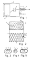
- Fig. 1 the end region of an empty envelope 13 (for example extruded plastic tube or steel tube) is indicated, into which a line 1, for example a coated fiber optic cable or an insulated electrical conductor, is to be blown.
- a container 15 is supplied with compressed air via the supply line 14, in which a container 15 is inserted
- Cross winding 4 is introduced with the required supply of line 1. If necessary, the withdrawal of line 1 into the empty envelope 13 can be supported by conveyor wheels 16.
- the empty envelope is sealed to the outlet connector 17 of the container 15.
- the pitch angle of the turns 1 with respect to a cross-sectional plane of the cross wrap 4 was set in all layers to a value which deviates only slightly from 8 o .
- the ratio of the winding speed and the speed of the axial guidance of the line 1 was changed in constant adaptation, so that the angle was kept within the range from 4 o to 10 o . Such an adjustment can take place continuously. In the preferred exemplary embodiment, this was done in stages after the production of a few winding layers, since a certain fluctuation range of the pitch angle is permitted.
- FIGS. 3, 4 and 5 Different cross-sectional shapes of a fiber-optic line 1 can be seen enlarged in FIGS. 3, 4 and 5 compared to position 3 in FIG. 2.
- the FO 6.7 or 8 have a diameter of about 250 ⁇ m including their plastic coating. They are surrounded by extruded sleeves 9, 10 and 11 respectively.
- a plastically deformable metal wire 13 is arranged in the plastic sleeve 11 parallel to the FO 8. The result is a flattened cross-sectional shape, which facilitates the winding of an even cheese.
- the plastically deformable metal wire 13 also maintains the winding position of the wire according to FIG. 2 against the elastic restoring forces of the optical fiber 8 at reversal points of the winding pitch, even if the surface of the plastic sleeve 11 is relatively smooth and adhesive-free.
- the optical fiber 6 is only surrounded by a particularly soft and not too thin plastic sheath, which is deformed into an elongated cross section similar to FIGS. 2 and 4 during winding of the package, so that it is at least approximately the same good winding results are achieved, as in the case of an elongated cross-sectional shape that was already present.
- plastics with an elastic modulus of less than 1 GPa have proven to be advantageously suitable. That is why thermoplastic polyurethane or soft polyvinyl chloride have been used in particular.
- stiffer shells 10 can be used, since the flexibility of the cross-sectional shape is achieved by a gel-like intermediate layer 12, which additionally prevents the attenuation increases in the optical fiber.
- FIG. 5 shows the cross-sectional shape that arises in the cross wrap. Originally, a circular plastic sheath 12 was extruded around the FO 7 concentrically.
- the cross wrap holds together excellently even without adhesive coating of the wires and can be unwound at high speed without problems.
Landscapes
- Physics & Mathematics (AREA)
- Engineering & Computer Science (AREA)
- Manufacturing & Machinery (AREA)
- General Physics & Mathematics (AREA)
- Optics & Photonics (AREA)
- Light Guides In General And Applications Therefor (AREA)
- Unwinding Of Filamentary Materials (AREA)
- Filamentary Materials, Packages, And Safety Devices Therefor (AREA)
- Electric Cable Installation (AREA)
- Storage Of Web-Like Or Filamentary Materials (AREA)
- Insulated Conductors (AREA)
- Making Paper Articles (AREA)
Applications Claiming Priority (2)
| Application Number | Priority Date | Filing Date | Title |
|---|---|---|---|
| DE3843777 | 1988-12-24 | ||
| DE3843777A DE3843777A1 (de) | 1988-12-24 | 1988-12-24 | Verfahren zum einblasen einer leitung in eine leerhuelle |
Publications (3)
| Publication Number | Publication Date |
|---|---|
| EP0376377A2 true EP0376377A2 (fr) | 1990-07-04 |
| EP0376377A3 EP0376377A3 (fr) | 1991-07-31 |
| EP0376377B1 EP0376377B1 (fr) | 1996-10-02 |
Family
ID=6370174
Family Applications (1)
| Application Number | Title | Priority Date | Filing Date |
|---|---|---|---|
| EP89203222A Expired - Lifetime EP0376377B1 (fr) | 1988-12-24 | 1989-12-18 | Procédé de mise en place pneumatique d'un film dans un tube |
Country Status (5)
| Country | Link |
|---|---|
| US (1) | US5046674A (fr) |
| EP (1) | EP0376377B1 (fr) |
| JP (1) | JP2848879B2 (fr) |
| DE (2) | DE3843777A1 (fr) |
| ES (1) | ES2094121T3 (fr) |
Families Citing this family (12)
| Publication number | Priority date | Publication date | Assignee | Title |
|---|---|---|---|---|
| US5364045A (en) * | 1993-06-07 | 1994-11-15 | Motorola, Inc. | Method and apparatus for dispensing electronic components |
| WO1995023988A1 (fr) * | 1994-03-02 | 1995-09-08 | British Telecommunications Plc | Outil d'installation pour fibre optique |
| US5503370A (en) * | 1994-07-08 | 1996-04-02 | Ctes, Inc. | Method and apparatus for the injection of cable into coiled tubing |
| US5599004A (en) * | 1994-07-08 | 1997-02-04 | Coiled Tubing Engineering Services, Inc. | Apparatus for the injection of cable into coiled tubing |
| NL1001960C2 (nl) * | 1995-12-21 | 1997-06-24 | Nederland Ptt | Werkwijze voor het installeren van een buis of een bundel buizen in een bestaand buisvormig kanaal. |
| DE69707301T2 (de) * | 1996-12-11 | 2002-06-27 | Koninklijke Kpn N.V., Groningen | Verfahren zum einführen eines kabelartigen elements in eine aufgerollte röhre auf einem halter |
| NL1004747C2 (nl) * | 1996-12-11 | 1998-06-15 | Nederland Ptt | Methode en inrichting voor het inbrengen van een kabelvormig element in een op of in een houder opgewonden langgerekte buisvormige omhulling. |
| US6296201B1 (en) * | 2000-01-28 | 2001-10-02 | Lucent Technologies Inc. | Method and apparatus for removing optical fiber |
| DE102007043719B3 (de) * | 2007-09-13 | 2009-07-30 | Atlas Elektronik Gmbh | Verfahren zur Herstellung einer Glasfaserspule |
| US9169351B2 (en) * | 2011-12-22 | 2015-10-27 | Johns Manville | Methods for making reinforced thermoplastic composites |
| CN106298063A (zh) * | 2016-08-05 | 2017-01-04 | 安庆市汇东机械有限责任公司 | 一种储线器 |
| US20190225454A1 (en) * | 2018-01-24 | 2019-07-25 | Milliken & Company | Dispensing system for elongated elements |
Family Cites Families (23)
| Publication number | Priority date | Publication date | Assignee | Title |
|---|---|---|---|---|
| US3079673A (en) * | 1958-06-04 | 1963-03-05 | Reynolds Metals Co | Method of inserting a close-fitting flexible heater element into an armored passage |
| US3156185A (en) * | 1960-12-20 | 1964-11-10 | Hermann Joachim | Triggering device for a movable body |
| DE1209839B (de) * | 1962-05-21 | 1966-01-27 | Land Und Seekabelwerke Ag | Selbsttragende, aus einem Strang gewickelte Spule |
| US3232557A (en) * | 1962-06-29 | 1966-02-01 | Archilithic Co | Control of continuous fiber rovings |
| CH413033A (de) * | 1963-06-21 | 1966-05-15 | Roland Dr Scheuchzer | Vorrichtung zum pneumatischen Einziehen einer Zugschnur in ein Leitungsrohr |
| US3412954A (en) * | 1965-10-28 | 1968-11-26 | Wall Ind Inc | Form stable coreless packages of foamed thermoplastic twine and processes of manufacture |
| US3559917A (en) * | 1967-09-05 | 1971-02-02 | Mackie & Sons Ltd J | Wound package |
| US3785137A (en) * | 1970-10-06 | 1974-01-15 | Goldsworthy Eng Inc | Apparatus and method for producing no-twist center-pull roving packages |
| US3703264A (en) * | 1971-06-30 | 1972-11-21 | Aichilithic Co The | Dispensing of fibrous material |
| US3750058A (en) * | 1971-12-08 | 1973-07-31 | Bell Telephone Labor Inc | Waveguide structure utilizing compliant helical support |
| FR2182381A5 (fr) * | 1972-04-28 | 1973-12-07 | Saint Gobain Pont A Mousson | |
| GB1436319A (en) * | 1972-11-10 | 1976-05-19 | Bicc Ltd | Optical guides |
| JPS5524324B2 (fr) * | 1975-01-11 | 1980-06-28 | ||
| GB1479427A (en) * | 1975-02-05 | 1977-07-13 | Bicc Ltd | Opticle cables |
| DE2551211B2 (de) * | 1975-11-12 | 1977-12-29 | Siemens AG, 1000 Berlin und 8000 München | Optisches kabel mit mehrschichtigem kunststoffmantel |
| US4185796A (en) * | 1976-12-13 | 1980-01-29 | The United States Of America As Represented By The Secretary Of The Army | Fiber optic missile guidance and control |
| DE2825845C2 (de) * | 1978-06-13 | 1985-06-05 | Siemens AG, 1000 Berlin und 8000 München | Optisches Nachrichtenkabel mit verstärktem Kunststoffmantel |
| US4326657A (en) * | 1980-05-19 | 1982-04-27 | The United States Of America As Represented By The Secretary Of The Army | Optical fiber dispenser |
| US4691896C1 (en) * | 1982-11-08 | 2001-05-08 | British Telecomm | Optical fibre transmission line |
| JP2788991B2 (ja) * | 1986-07-16 | 1998-08-20 | ブリティシュ・テレコミュニケーションズ・パブリック・リミテッド・カンパニ | 伝送線路部材の推進力制御装置および伝送線路吹き流し装置 |
| US4726564A (en) * | 1986-09-15 | 1988-02-23 | Lynn Randy R | Pull-line cannister |
| US4696438A (en) * | 1986-10-24 | 1987-09-29 | American Telephone And Telegraph Company At&T Technologies, Inc. | Spool for holding optical fiber |
| US4883337A (en) * | 1988-08-29 | 1989-11-28 | The Charles Stark Draper Laboratory, Inc. | Low strain optical fiber coil |
-
1988
- 1988-12-24 DE DE3843777A patent/DE3843777A1/de not_active Withdrawn
-
1989
- 1989-12-05 US US07/446,508 patent/US5046674A/en not_active Expired - Fee Related
- 1989-12-18 ES ES89203222T patent/ES2094121T3/es not_active Expired - Lifetime
- 1989-12-18 EP EP89203222A patent/EP0376377B1/fr not_active Expired - Lifetime
- 1989-12-18 DE DE58909741T patent/DE58909741D1/de not_active Expired - Fee Related
- 1989-12-21 JP JP1332528A patent/JP2848879B2/ja not_active Expired - Lifetime
Also Published As
| Publication number | Publication date |
|---|---|
| DE3843777A1 (de) | 1990-07-05 |
| DE58909741D1 (de) | 1996-11-07 |
| ES2094121T3 (es) | 1997-01-16 |
| US5046674A (en) | 1991-09-10 |
| JP2848879B2 (ja) | 1999-01-20 |
| EP0376377B1 (fr) | 1996-10-02 |
| JPH02215656A (ja) | 1990-08-28 |
| EP0376377A3 (fr) | 1991-07-31 |
Similar Documents
| Publication | Publication Date | Title |
|---|---|---|
| DE2523738C2 (de) | Optisches Nachrichtenkabel | |
| DE69506705T2 (de) | Faseroptisches kabel mit erweitertem kontraktionsbereich,verfahren und vorrichtung zur herstellung des kabels | |
| DE2701631C2 (de) | Optisch leitendes Element | |
| DE2832441C2 (de) | Lichtleiterkabel sowie Verfahren und Vorrichtung zur Herstellung desselben | |
| EP0376377B1 (fr) | Procédé de mise en place pneumatique d'un film dans un tube | |
| DE2818574C2 (de) | Verfahren zur kontinuierlichen Herstellung von Kabel-Elementen mit optischen Fasern und Vorrichtung zur Durchführung des Verfahrens | |
| DE2922986C2 (fr) | ||
| DE2507649A1 (de) | Optisches kabel fuer nachrichtenuebertragungszwecke | |
| DE69225531T2 (de) | Verfahren und Vorrichtung zur Herstellung eines faseroptischen Kabels | |
| DE4101082C1 (fr) | ||
| DE3109469C2 (fr) | ||
| DE2914217C2 (de) | Kassette zur Aufnahme der Vorratslängen von Lichtleitfasern | |
| DE1810717A1 (de) | Verbesserungen an fiberoptischen Multifibern,an daraus gebildeten Vorrichtungen,und Verfahren zur Herstellung beider | |
| DE69311103T2 (de) | Verfahren und Vorrichtung zum reversierenden Verseilen | |
| DE2701650C2 (de) | Ader für ein optisches Kabel bzw. ein optisches Kabelelement | |
| EP0376379A2 (fr) | Procédé de fabrication d'un câble optique | |
| DE3027743C2 (fr) | ||
| DE102017222107B4 (de) | Verfahren sowie Vorrichtung zur Herstellung einer Leitung | |
| DE3526823A1 (de) | Element mit mehreren lichtwellenleitern | |
| DE69213110T2 (de) | Herstellungsverfahren für ein optisches Kabel aus Hohladern und daraus resultierendes Kabel | |
| EP0258839A2 (fr) | Câble optique et procédé pour sa fabrication | |
| EP1144296A1 (fr) | Dispositif de distribution pour lignes de transmission de donnees, et procede de production d'un tel dispositif de distribution | |
| EP0327164B1 (fr) | Procédé de fabrication d'un câble optique | |
| EP0342663B1 (fr) | Bobine construite avec un guide d'onde optique en forme de câble | |
| EP0228132A2 (fr) | Méthode de fabrication d'un câble optique |
Legal Events
| Date | Code | Title | Description |
|---|---|---|---|
| PUAI | Public reference made under article 153(3) epc to a published international application that has entered the european phase |
Free format text: ORIGINAL CODE: 0009012 |
|
| AK | Designated contracting states |
Kind code of ref document: A2 Designated state(s): DE ES FR GB IT |
|
| PUAL | Search report despatched |
Free format text: ORIGINAL CODE: 0009013 |
|
| AK | Designated contracting states |
Kind code of ref document: A3 Designated state(s): DE ES FR GB IT |
|
| 17P | Request for examination filed |
Effective date: 19920131 |
|
| 17Q | First examination report despatched |
Effective date: 19931011 |
|
| RAP1 | Party data changed (applicant data changed or rights of an application transferred) |
Owner name: ALCATEL KABEL AG & CO. |
|
| GRAG | Despatch of communication of intention to grant |
Free format text: ORIGINAL CODE: EPIDOS AGRA |
|
| GRAH | Despatch of communication of intention to grant a patent |
Free format text: ORIGINAL CODE: EPIDOS IGRA |
|
| GRAH | Despatch of communication of intention to grant a patent |
Free format text: ORIGINAL CODE: EPIDOS IGRA |
|
| GRAA | (expected) grant |
Free format text: ORIGINAL CODE: 0009210 |
|
| ITF | It: translation for a ep patent filed | ||
| AK | Designated contracting states |
Kind code of ref document: B1 Designated state(s): DE ES FR GB IT |
|
| REF | Corresponds to: |
Ref document number: 58909741 Country of ref document: DE Date of ref document: 19961107 |
|
| GBT | Gb: translation of ep patent filed (gb section 77(6)(a)/1977) |
Effective date: 19961025 |
|
| REG | Reference to a national code |
Ref country code: ES Ref legal event code: FG2A Ref document number: 2094121 Country of ref document: ES Kind code of ref document: T3 |
|
| ET | Fr: translation filed | ||
| PLBE | No opposition filed within time limit |
Free format text: ORIGINAL CODE: 0009261 |
|
| STAA | Information on the status of an ep patent application or granted ep patent |
Free format text: STATUS: NO OPPOSITION FILED WITHIN TIME LIMIT |
|
| 26N | No opposition filed | ||
| PGFP | Annual fee paid to national office [announced via postgrant information from national office to epo] |
Ref country code: GB Payment date: 19991112 Year of fee payment: 11 |
|
| PGFP | Annual fee paid to national office [announced via postgrant information from national office to epo] |
Ref country code: FR Payment date: 19991123 Year of fee payment: 11 Ref country code: DE Payment date: 19991123 Year of fee payment: 11 |
|
| PGFP | Annual fee paid to national office [announced via postgrant information from national office to epo] |
Ref country code: ES Payment date: 19991216 Year of fee payment: 11 |
|
| PG25 | Lapsed in a contracting state [announced via postgrant information from national office to epo] |
Ref country code: GB Free format text: LAPSE BECAUSE OF NON-PAYMENT OF DUE FEES Effective date: 20001218 |
|
| GBPC | Gb: european patent ceased through non-payment of renewal fee |
Effective date: 20001218 |
|
| PG25 | Lapsed in a contracting state [announced via postgrant information from national office to epo] |
Ref country code: FR Free format text: LAPSE BECAUSE OF NON-PAYMENT OF DUE FEES Effective date: 20010831 |
|
| REG | Reference to a national code |
Ref country code: FR Ref legal event code: ST |
|
| PG25 | Lapsed in a contracting state [announced via postgrant information from national office to epo] |
Ref country code: DE Free format text: LAPSE BECAUSE OF NON-PAYMENT OF DUE FEES Effective date: 20011002 |
|
| PG25 | Lapsed in a contracting state [announced via postgrant information from national office to epo] |
Ref country code: ES Free format text: LAPSE BECAUSE OF NON-PAYMENT OF DUE FEES Effective date: 20011219 |
|
| REG | Reference to a national code |
Ref country code: ES Ref legal event code: FD2A Effective date: 20020112 |
|
| PG25 | Lapsed in a contracting state [announced via postgrant information from national office to epo] |
Ref country code: IT Free format text: LAPSE BECAUSE OF NON-PAYMENT OF DUE FEES;WARNING: LAPSES OF ITALIAN PATENTS WITH EFFECTIVE DATE BEFORE 2007 MAY HAVE OCCURRED AT ANY TIME BEFORE 2007. THE CORRECT EFFECTIVE DATE MAY BE DIFFERENT FROM THE ONE RECORDED. Effective date: 20051218 |