EP0376417B1 - Connexion à plusieurs broches - Google Patents
Connexion à plusieurs broches Download PDFInfo
- Publication number
- EP0376417B1 EP0376417B1 EP89250106A EP89250106A EP0376417B1 EP 0376417 B1 EP0376417 B1 EP 0376417B1 EP 89250106 A EP89250106 A EP 89250106A EP 89250106 A EP89250106 A EP 89250106A EP 0376417 B1 EP0376417 B1 EP 0376417B1
- Authority
- EP
- European Patent Office
- Prior art keywords
- hook
- bolt connection
- stops
- bolt
- connection according
- Prior art date
- Legal status (The legal status is an assumption and is not a legal conclusion. Google has not performed a legal analysis and makes no representation as to the accuracy of the status listed.)
- Expired - Lifetime
Links
Images


Classifications
-
- B—PERFORMING OPERATIONS; TRANSPORTING
- B66—HOISTING; LIFTING; HAULING
- B66C—CRANES; LOAD-ENGAGING ELEMENTS OR DEVICES FOR CRANES, CAPSTANS, WINCHES, OR TACKLES
- B66C23/00—Cranes comprising essentially a beam, boom, or triangular structure acting as a cantilever and mounted for translatory of swinging movements in vertical or horizontal planes or a combination of such movements, e.g. jib-cranes, derricks, tower cranes
- B66C23/62—Constructional features or details
- B66C23/64—Jibs
- B66C23/70—Jibs constructed of sections adapted to be assembled to form jibs or various lengths
Definitions
- the invention relates to multi-section bolt connections, in particular for crane boom parts which are preferably designed in a lattice construction.
- Such bolt connections are known for example from DE-PS 37 06 301 and are used, among other things, to connect boom sections, in particular lattice tower parts, so-called bolt joints being welded to the belt tubes.
- the connections are usually made in three parts and each consist of a fork piece, a bracket piece and a bolt.
- the respective fork piece with the associated bracket piece When assembling the boom parts or shots, the respective fork piece with the associated bracket piece must first be aligned with its bores, and then a bolt must be inserted or hammered in. At each connection point there are four of these three-part connections, namely two in the upper and two in the lower flange.
- the fourth bolt can often only be inserted or driven in with considerable effort. This does not only result from the manufacturing or mounting tolerances for the fork pieces, given the parts to be connected, such as the boom sections and bracket pieces, but in particular from the fact that there are two degrees of freedom of movement in the vertical boom longitudinal plane for the shots during assembly, since only transverse to the longitudinal axis of the boom by the shape of the fork piece and bracket piece - the latter is to be inserted into the fork piece with its "eyelet" - fixation is given. In this regard, the aligned position must be reached manually in the vertical boom longitudinal plane.
- the bolts in the upper belt level can usually only be reached with the help of a work platform, which increases the assembly effort even further.
- the invention is therefore based on the object of improving a multi-section bolt connection of the type mentioned in such a way that it can be assembled not only faster but also more securely, in particular the necessary insertion or insertion of bolts is facilitated.
- this idea is realized in claim 1.
- the idea of the solution is therefore essentially that the bracket piece in the fork piece in the plane perpendicular to its axis of the bore is almost positively brought to a stop in such a way that the bores are then aligned with the fork piece and bracket piece and the respective bolt can be inserted without difficulty.
- the inventive self-centering limitation of a degree of freedom of movement by at least one pair of stops is preferably by at least one hook-shaped stop of at least one pair of stops (hook stop) achieved, in a further embodiment of the invention for each pair of stops having a hook-shaped stop a thrust block corresponding to the hook or a counter pressure surface belongs.
- the hook-shaped stop or the hook is preferably provided on the bracket side of the connection, while the push block corresponding to the hook or the counter pressure surface is provided on the fork side.
- the hook and push block or counter pressure surface can also be integrated into the bracket piece or fork piece. In any case, an exact fixation of the connection point of the jib parts to be connected is achieved by assigning the stop pairing according to the invention.
- the assembly time can be optimized not least by the fact that the working platform mentioned at the outset, which is necessary to reach the bolts in the upper belt level, is generally eliminated.
- two pairs of stops are expediently provided in the upper chord level of each boom joint.
- An even better fixation of the butt joint can be achieved by additionally providing at least one pair of stops (surface stop) consisting of two flat surfaces, so that in a preferred embodiment two hook stops in the top flange level and two surface stops in the bottom flange level of each boom joint for easy assembly and also take care of disassembly.
- the lattice tower parts can be very easily by means of the hook stops provided in the upper belt level, and preferably one each in the two corners of the upper belt level to be connected in the joint area, that is to say at the ends of the belt tubes to be connected thereby bring into the aligned position of the holes for the bolts to be brought in position that first the hook stops are brought into engagement, the bolts being inserted into the associated fork pieces prior to assembly because of the hook-shaped design of the bracket pieces, that is to say it needs to be in the Upper belt level only to be "hooked in”.
- the third degree of freedom is then finally limited, namely by these surface stops, i.e. In the stretched, aligned position of the lattice tower parts to be connected, the surfaces forming the respective surface stop, which are provided on the fork piece and correspondingly on the bracket piece, then lie against one another in the lower chord plane in such a way that the bolt is now only inserted or effortlessly hammered in needs.
- each stop pair On the respective To provide bracket piece or to form from this in a preferred embodiment, ie the bracket piece itself forms the hook instead of a hole closed on all sides. Accordingly, one surface of each surface stop is preferably formed by a flat end face on the bracket piece and the other surface is provided in the foot of the fork piece of this surface stop.
- the hook or hooks of each stop pair is or are deformed on the end face to form a stop pressure surface which, when assembled, preferably runs essentially vertically and the corresponding counter pressure surface provided in the foot of the fork piece lies flat.
- a further improvement in the transmission of compressive forces in the upper chord plane can be achieved if the flat counter-pressure surface merges from the center of the boom into a concave surface which, in its curvature, matches the outer contour of the hook associated with it, which in the assembled state fits snugly against the outer surface of the hook end , with the hooks pointing away from the middle of the boom.
- the hooks should wrap around the associated bolt by between 90 ° and 180 ° in the assembled state, preferably on the side facing the counterpressure surface when arranged in the top flange level up to above the horizontal diameter of the bolt and with arrangement in the lower chord level to below the horizontal diameter.
- FIG. 1 two interconnected boom sections 1 and 2 are shown with their ends carrying the bolt connections in a side view.
- Fig. 2 which shows a section through the upper belt level, the invention according to a first embodiment consists of normal bolt joints, each formed from a fork piece 3 and a bracket piece 4, whereby to complete the bolt joint connection, each bolt 5 (in the exemplary embodiment shown overall four pieces for this connection point) are required.
- the upper and lower chord tubes 7 and 8 connecting cross struts are designated.
- the embodiment according to FIGS. 1 and 2 has a pair of stops in the upper belt level in a first embodiment of the invention, which is designed as a hook stop and, in the exemplary embodiment shown, consists of one on the upper side of the upper belt tubes 7 in the region of the end of the boom section 2 is welded or otherwise permanently attached to the hook 9, the hook-shaped free end 9a of which extends above the fork side of the section 1 and engages behind a thrust block 11 attached to the top of each top chord tube.
- the invention provides for a further pair of stops in the area of the lower chord tubes, specifically as a flat stop, which consists of a flat end face 12 of the bracket pieces and one with the flattening 12 corresponding and this in the assembled state just lying against the surface 13 in the foot of the fork pieces 3 of the lower flange level.
- a flat stop which consists of a flat end face 12 of the bracket pieces and one with the flattening 12 corresponding and this in the assembled state just lying against the surface 13 in the foot of the fork pieces 3 of the lower flange level.
- FIGS. 3 to 5 A further development of the previously described connection shown in FIGS. 1 and 2 is shown in FIGS. 3 to 5, the hook according to the invention being integrated with the corresponding thrust block in the bow or fork pieces of the upper belt level in such a way that a bolt connection is produced , which are aligned in their outer contours with the outer contours of the stirrup and fork pieces, and thus do not extend beyond the upper edge of the upper chord tubes.
- This stop version is structured as follows: The lower flange level is constructed essentially as in the exemplary embodiment according to FIGS.
- the hook stop in the upper belt level is integrated into the conventional bolt connection.
- the component fulfilling the hook function consists essentially of an upper side T-shaped extension 14 of the bracket piece 15 attached to the upper chord tube 7 of the jib section 2 (see in particular FIG. 5), so that there is an extension (end section that runs perpendicular to the longitudinal axis of the upper chord tubes 7, which are aligned in the assembled state, of the two shots 1 and 2 to be connected of the T-piece), which fits into a corresponding, top-side recess 16 in the foot region of the fork piece 17 shown in broken lines.
- the recess 16 narrows slightly conically towards its base and the T-extension has correspondingly inclined fitting surfaces, of which the bolts 5 not shown in FIG. 5 Receiving holes 18 facing surface 19 represents the hook-shaped stop of the bracket piece according to the invention or takes over its function, while the opposite surface 20 of the recess 16 of the fork piece 17 forms the thrust block or the counter pressure surface.
- this embodiment of the invention aligns the top surfaces of the bolt connection, so that there is a smooth finish to the outside.
- the respective hook stops only serve to make assembly of the jib parts easier and are not designed and provided for power transmissions during operation of the crane; the tensile and compressive forces in the upper chord plane are still transmitted there by the normal bolt joint, but the advantages of the invention which relate to the ease of assembly are fully and reliably achieved.
- the invention is in one Designed in such a way that, in addition to the ease of assembly, there is the additional advantage that, via the bolt joint of the upper belt level, the compressive forces in this plane are also transmitted without bolt loading - in contrast to the previously described exemplary embodiments according to FIGS. 1 to 5 - while the tensile forces are being transmitted be transferred from the hook to the assigned pin.
- the flats 12 and the corresponding counter surfaces 13, which are primarily centering aids for the bolts in the lower flange also transmit compressive forces in this plane without bolt loading.
- FIGS. 6 and 7, show the two ends of the two boom sections 1 and 2 to be connected before they are joined, specifically in FIG. 6 in a side view with their respective upper chord tubes 7 and lower chord tubes 8, while the FIG. 7 shows a top view according to view A in FIG. 6.
- the fork piece 21 is equipped with a counter pressure surface 22 in its foot region.
- the bracket piece of the upper belt level - two at each joint, ie one for each upper belt tube - is designed as a hook 23 which is open at the top; the bolt 5 receiving the bracket piece is not closed on all sides, the top opening being at least as wide as the length of the diameter of the bolt 5.
- the hook 23 is deformed into a stop pressure surface 24 which, like the counter pressure surface 22, with which it corresponds in the assembled state and with which it then lies flat, is aligned substantially vertically and its dimensions are adapted to it.
- a reinforcement 25 extends backwards, which serves to absorb the offset torque in the hook 23.
- the bolt joint is designed in accordance with the exemplary embodiments according to FIGS. 1 to 5, i.e. the bracket piece 4 is provided at the free end with a flattened portion 12 which also extends substantially vertically and corresponds to the counter surface 13 provided in the foot of the fork piece 3.
- the flattened area 12 thus represents the stop pressure surface in the lower flange level, by means of which the bolt centering in the lower flange level is achieved in cooperation with the corresponding counter pressure surface 13.
- the previously described embodiment of the invention is designed as a four-section connection, which leads to the fact that the bolts 5 can be kept smaller in diameter than in a two-section connection, because instead of the two interfaces of the bolts that were previously subject to shear 5 there are now four so that ultimately the entire connection can be made much smaller.
- the design of the fork and bracket pieces is the same as in the previously described exemplary embodiment, so that reference can be made to them and the corresponding parts are provided with the same reference numbers.
- Due to the four-cut nature of the upper belt level in the bracket piece there is of course a double formation of the hooks 23, as can be seen in particular from FIG. 9. These double hooks 23 then engage in the assembled state in the correspondingly double recesses of the associated fork piece 21 with the bolts 5 reaching behind.
- the counter pressure surfaces 22 and 13 and the stop pressure surfaces 24 and 12 are correspondingly doubled.
- Fig. 10 the two boom sections 1 and 2 are shown in an intermediate position during the assembly process, details of the inventive design of the bolt joint with hook stop are shown enlarged in two versions in the lower part.
- the assembly takes place as follows:
- the cantilever parts to be joined are aligned perpendicular to the plane of the drawing by means of the upper flange-side bolt connections via the fork and bracket piece, but hooked in the drawing plane with their longitudinal axes at an angle to one another such that the hook-shaped bracket pieces 23 engage under the respectively assigned bolts 5, as is the case in detail X clearly emerges.
- the hooks 23 are designed in such a way that problem-free hooking of the boom part 2 is ensured, the stop pressure surfaces 24 and the counter pressure surfaces 22 having enough play in this assembly situation for the subsequent alignment movement up to the aligned position of the boom parts or shots according to FIG. 11.
- the stop pressure surfaces 24 of the upper belt level also fit snugly against the counterpressure surfaces 22 corresponding to them, so that, in addition to fixing the position, they are also able to transmit the compressive forces occurring in the upper belt level, since this no longer possible due to the hook 23 opened laterally upwards and is therefore no longer necessary.
- the corresponding stop pressure surfaces 12 and counter pressure surfaces 13 are also in contact with one another and are also able to transmit compressive forces after they have been fixed and fixed during assembly for correct, elongated, aligned alignment of the boom sections 1 to be connected and served 2.
- Fig. 10 two possible variants of the formation of the counter pressure surface 22 in the upper chord-side fork piece are shown as detail X.
- the counter pressure surface 22 is flat in the lower region and adapted to the stop pressure surface 24 in terms of its dimensions and its orientation, while it is towards the top in the example shown above, approximately from the central longitudinal axis of the top flange tube of the boom section 1 towards the rear from the free end is obliquely aligned, whereas
- the counter pressure surface 22 moves away from the middle of the boom above the central longitudinal axis of the upper chord tube of the boom section 1 into a concave surface 27, whose curvature is adapted to the outer contour of the hook associated with it, which fits snugly in the assembled state of the outer surface 27a of the hook end.
- This achieves an extraordinarily favorable contact situation, which ensures that the compressive forces are introduced centrally into the top chord tubes of the weft 1, since force-transmitting surfaces now abut one another both above and below the central longitudinal axi
- the exemplary embodiments according to FIGS. 6 to 10 have the particular advantage that the bolts 5 are generally relieved that on the one hand the hooks on the upper belt side with their stop pressure surfaces 24 in interaction with the counter pressure surfaces 22 and on the other hand the contact surfaces 12 and 13 transmit forces in the contact state, so that the bolt is relieved in these operating states.
- the stop pressure surfaces and counter pressure surfaces in the upper chord as well as in the lower chord level have an additional securing effect and, in particular, relieve the bolts gently in the event of applied compressive forces which are then transmitted by them.
- the different pairs of stops can be attached or combined in the respective special requirements according to the modified form and number.
- the lower flange level in the case of basically hook-shaped bolt connections in the upper flange level.
- the lower chord plane can have two cuts be designed with correspondingly larger bolts 5, but a four-bolt connection according to FIG. 12b, for example, allows the diameter of the bolts 5 to be reduced.
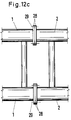
- a flange connection can also be provided in the lower flange plane according to FIG.
- the shots 1 and 2 to be connected are provided at their mutually facing ends with corresponding flanges 28 which are to be connected by means of screws 29.
- the flanges 28 then serve as stops with their free contact surfaces facing one another, and, with a corresponding design, can also perform assembly management and fixing tasks similar to the fork and bracket pieces designed according to the invention, while they then operate both compressive and tensile forces are able to transmit.
Landscapes
- Engineering & Computer Science (AREA)
- Mechanical Engineering (AREA)
- Jib Cranes (AREA)
- Mutual Connection Of Rods And Tubes (AREA)
Claims (13)
- Liaison à boulons à section multiple pour des parties (1,2) de flèche de grue réalisées de préférence sous forme de treillis, dans lesquelles un appariement de butée est à chaque fois associé à un boulon (5) ou à une paire de boulons, et une chape (3) avec une pièce d'étrier (4) pour un boulon (5) est présente dans le plan de la membrure inférieure (8) lorsque les parties (1,2) de flèche de grue sont prêtes au montage,
caractérisée en ce que l'appariement de butée, dans le plan de la membrure supérieure (7), est formé d'une chape (21) à boulon (5) et d'une butée (23) en forme de crochet, un bloc de poussée (11,12) ou une surface de contre-pression (22), correspondant à un crochet (9,14;23) appartient à chaque appariement de butée présentant une butée en forme de crochet, et, dans le plan de la membrure inférieure (8), est prévu au moins un appariement de butée (butée de surface) constitué de deux surfaces planes (12,13). - Liaison à boulons selon la revendication 1,
caractérisée en ce que la butée en forme de crochet est agencée sur l'étrier (4,23), et le bloc de poussée (11) ou la surface de contre-pression (22) est agencé sur la chape (3 ou 21) de la liaison à boulons ou, à chaque fois, intégré(e) dans celui-ci ou celle-ci. - Liaison à boulons selon la revendication 1 ou 2,
caractérisée par une réalisation intégrée du bloc de poussée (20) et du crochet (14) dans la chape (17) ou la pièce d'étrier (15), la structure étant extérieurement alignée (figure 5). - Liaison à boulons selon la revendication 1,
caractérisée par deux appariements de butée dans le plan de la membrure supérieure de chaque partie de flèche. - Liaison à boulons selon la revendication 1,
caractérisée par deux butées à crochet dans le plan de la membrure supérieure et deux butées de surface dans le plan de la membrure inférieure de chaque partie de flèche. - Liaison à boulons selon une ou plusieurs des revendications 1 à 5,
caractérisée en ce que le ou les crochets (9,14,23) de chaque appariement de butée sont prévus sur la pièce d'étrier respective (4,15) ou sont formés à partir de celle-ci (23). - Liaison à boulons selon une ou plusieurs des revendications 1 à 6,
caractérisée en ce qu'une surface de chaque butée de surface est formée par un aplatissement frontal (12) sur la pièce d'étrier (4), et l'autre surface (13) est prévue au pied de la chape (3). - Liaison à boulons selon une ou plusieurs des revendications 1 à 7,
caractérisée en ce que le ou les crochets (23) de chaque appariement de butée sont formés frontalement à une surface de pression de butée (24). - Liaison à boulons selon la revendication 8,
caractérisée en ce que la surface de pression de butée (24), dans l'état monté, s'étend généralement verticalement, et la surface de contre-pression (22) correspondante, prévue au pied de la chape (21), y est adjacente de façon plane. - Liaison à boulons selon la revendication 9 ou 12,
caractérisée en ce que la surface de contre-pression plane (22), au loin du centre de la flèche, se convertit en une surface concave (27) adaptée, en ce qui concerne sa courbure, au contour externe du crochet (23) qui y est associé. - Liaison à boutons selon une ou plusieurs des revendications 1 à 10,
caractérisée en ce que les crochets (23), dans l'état monté, s'éloignent, avec leur ouverture, du centre (26) de la flèche. - Liaison à boutons selon une ou plusieurs des revendications 1 à 11,
caractérisée en ce que les crochets (23), dans l'état monté, entourent le bouton (5) à chaque fois correspondant sur 90° à 180°. - Liaison à boutons selon une ou plusieurs des revendications 1 à 12,
caractérisée en ce que les crochets (23), dans l'état monté, entourent le bouton (5), sur la face en regard de la surface de contre-pression (22), lorsqu'il est agencé dans le plan de la membrure supérieure jusqu'au-dessus de son diamètre horizontal et lorsqu'il est agencé dans le plan de la membrure inférieure jusqu'au-dessous de son diamètre horizontal.
Applications Claiming Priority (2)
| Application Number | Priority Date | Filing Date | Title |
|---|---|---|---|
| DE3842726A DE3842726C3 (de) | 1988-12-19 | 1988-12-19 | Mehrschnittige Bolzenverbindung |
| DE3842726 | 1988-12-19 |
Publications (2)
| Publication Number | Publication Date |
|---|---|
| EP0376417A1 EP0376417A1 (fr) | 1990-07-04 |
| EP0376417B1 true EP0376417B1 (fr) | 1994-03-02 |
Family
ID=6369539
Family Applications (1)
| Application Number | Title | Priority Date | Filing Date |
|---|---|---|---|
| EP89250106A Expired - Lifetime EP0376417B1 (fr) | 1988-12-19 | 1989-12-04 | Connexion à plusieurs broches |
Country Status (5)
| Country | Link |
|---|---|
| US (1) | US5082128A (fr) |
| EP (1) | EP0376417B1 (fr) |
| JP (1) | JP2660240B2 (fr) |
| DE (2) | DE3842726C3 (fr) |
| RU (1) | RU1801180C (fr) |
Families Citing this family (35)
| Publication number | Priority date | Publication date | Assignee | Title |
|---|---|---|---|---|
| DE9013209U1 (de) * | 1990-09-18 | 1990-12-20 | Liebherr-Werk Ehingen Gmbh, 7930 Ehingen | Bolzenverbindung, vorzugsweise für Auslegerzwischenstücke für Kräne |
| US5199586A (en) * | 1991-07-25 | 1993-04-06 | The Manitowoc Company, Inc. | Quick-connect sectional boom members for cranes and the like |
| CA2108958C (fr) * | 1993-01-08 | 1996-12-03 | David J. Pech | Raccord de segments d'anneau |
| DE4402005A1 (de) * | 1994-01-18 | 1995-07-20 | Mannesmann Ag | Ein- oder mehrschnittige Bolzenverbindung für Kran-Auslegerteile |
| DE19544076C1 (de) * | 1995-11-25 | 1997-04-30 | Expo Mart Inc | Bausatz zur Herstellung von Tragwerken aus Tragstangen und Verbindungselementen |
| EP0794149B1 (fr) * | 1996-03-04 | 2004-02-25 | Manitowoc Crane Companies, Inc. | Articulation enlevable pour plier une flèche articulée |
| US6131750A (en) * | 1997-05-28 | 2000-10-17 | Link-Belt Construction Equipment Co | Connection system for boom extension |
| DE29807347U1 (de) | 1998-04-24 | 1998-07-30 | Tyroller Hydraulik Herzberg GmbH, 04916 Herzberg | Anordnung zur Befestigung von Zusatzgeräten, insbesondere von Ladekränen an kleineren Lastkraftfahrzeugen |
| US6213318B1 (en) * | 1999-03-01 | 2001-04-10 | Manitowoc Crane Group, Inc. | Rotatable connection system for crane boom sections |
| FR2853891B1 (fr) * | 2003-04-17 | 2006-05-19 | Potain Sa | Dispositif d'assemblage demontable des elements de fleche d'une grue a tour |
| DE102005006456A1 (de) | 2005-02-12 | 2006-08-24 | Gottwald Port Technology Gmbh | Kranausleger in Gitterbauweise |
| US7850016B2 (en) * | 2005-03-23 | 2010-12-14 | James Trisler | Apparatus for storing lengths of pipe |
| DE202005008602U1 (de) * | 2005-06-02 | 2006-10-19 | Liebherr-Werk Biberach Gmbh | Ausleger |
| DE102006060347B4 (de) * | 2006-12-20 | 2008-09-25 | Liebherr-Werk Ehingen Gmbh | Gitterstück für einen mobilen Großkran und Verfahren zu seinem Aufrichten |
| US8397924B2 (en) | 2008-09-19 | 2013-03-19 | Manitowoc Crane Companies, Llc | Drum frame system for cranes |
| JP2009149438A (ja) | 2007-11-29 | 2009-07-09 | Manitowoc Crane Companies Ltd | クレーンブームセグメント用の接続システム |
| DE202008016876U1 (de) * | 2008-12-19 | 2010-09-23 | Liebherr-Werk Ehingen Gmbh | Drehverbindung |
| ES2374015B1 (es) * | 2009-02-05 | 2012-10-30 | Linden Comansa, S.L. | Grúa torre sin cúspide. |
| DE102009022262A1 (de) * | 2009-05-22 | 2010-11-25 | Terex Demag Gmbh | Winkelverstellung eines Auslegersystems |
| DE202010004584U1 (de) * | 2010-04-06 | 2011-10-05 | Liebherr-Werk Ehingen Gmbh | Gittermastkran und Gittermastausleger |
| JP2011225343A (ja) * | 2010-04-21 | 2011-11-10 | Kobe Steel Ltd | ラチスブーム |
| US8739988B2 (en) * | 2010-09-20 | 2014-06-03 | Manitowoc Crane Companies, Llc | Pinned connection system for crane column segments |
| USD670474S1 (en) * | 2011-06-14 | 2012-11-06 | Eepos Gmbh | Guide rail for mobile crane |
| CN102500939B (zh) * | 2011-11-03 | 2014-10-15 | 常州海杰冶金机械制造有限公司 | 塔式起重机平衡臂的装配方法 |
| CN102556857A (zh) * | 2011-12-12 | 2012-07-11 | 中联重科股份有限公司 | 桁架臂对接结构,具有其的桁架臂以及桁架臂起重机 |
| CN102627229B (zh) * | 2012-04-11 | 2015-03-11 | 中联重科股份有限公司 | 销轴连接结构及其安装和拆卸方法、塔式起重机 |
| EP2746214B1 (fr) | 2012-12-20 | 2016-04-27 | Manitowoc Crane Companies, LLC | Système de connecteur de colonne |
| CN103303819A (zh) * | 2013-07-01 | 2013-09-18 | 张家港市天运建筑机械有限公司 | 塔机臂架下弦 |
| CN104555757A (zh) * | 2013-10-11 | 2015-04-29 | 北汽福田汽车股份有限公司 | 连接臂架及设有该连接臂架的臂架系统和工程设备 |
| CN104512820A (zh) * | 2014-12-19 | 2015-04-15 | 徐州建机工程机械有限公司 | 一种平头塔机起重臂连接的新型结构 |
| DE102017000525B4 (de) * | 2016-02-10 | 2024-02-29 | Liebherr-Werk Ehingen Gmbh | Gitterstückelement und Gitterstück für Kranausleger |
| CA2972085C (fr) * | 2017-06-28 | 2018-05-08 | John Rene Spronken | Dispositif de soulevement ou support d'une charge, et elements et connecteurs destines audit dispositif |
| RU174726U1 (ru) * | 2017-07-04 | 2017-10-30 | Федеральное государственное бюджетное образовательное учреждение высшего образования "Брянский государственный университет имени академика И.Г. Петровского" | Шарнир устройства соединения звеньев крано-манипуляторной установки |
| DE102019110608A1 (de) * | 2019-04-24 | 2020-10-29 | Tadano Demag Gmbh | Fahrzeugkran mit verlängerbarem Abspannmast |
| CN112520596A (zh) * | 2021-01-22 | 2021-03-19 | 郑州科润机电工程有限公司 | 一种塔式起重机水平悬臂式起重臂的节间连接结构 |
Family Cites Families (29)
| Publication number | Priority date | Publication date | Assignee | Title |
|---|---|---|---|---|
| US534507A (en) * | 1895-02-19 | Rod-coupling | ||
| DD74333A (fr) * | ||||
| US1807782A (en) * | 1931-06-02 | of milwaukee | ||
| US608000A (en) * | 1898-07-26 | Erman | ||
| NL193470A (fr) * | ||||
| US1868508A (en) * | 1929-04-12 | 1932-07-26 | William H Stewart | Sectional rod and coupling member therefor |
| US1941952A (en) * | 1931-12-26 | 1934-01-02 | Manitowoc Shipbuilding Corp | Boom construction |
| US2115194A (en) * | 1936-11-17 | 1938-04-26 | Burton George | Coupling for sewer cleaning rods |
| US2446410A (en) * | 1943-11-27 | 1948-08-03 | Kibbey W Couse | Combination pry-and-boom structure |
| US2649210A (en) * | 1949-08-09 | 1953-08-18 | Marchese Anthony | Folding boom crane combination |
| FR1250050A (fr) * | 1959-12-12 | 1961-03-24 | Système de liaison rapide pour éléments de charpentes métalliques ou particulièrement grues | |
| US3080068A (en) * | 1960-12-15 | 1963-03-05 | Alphie O Felkner | Sectional boom for cranes |
| US3085695A (en) * | 1961-03-23 | 1963-04-16 | Carl A Miller | Hinge for crane boom |
| US3250401A (en) * | 1964-12-17 | 1966-05-10 | Bucyrus Erie Co | Self-erecting tower crane with bayonet joints between sections |
| US3323660A (en) * | 1965-09-21 | 1967-06-06 | Northwest Engineering Corp | Lattice boom construction |
| NL6617808A (fr) * | 1966-12-19 | 1968-06-20 | ||
| DE1285150B (de) * | 1967-06-01 | 1968-12-12 | Demag Zug Gmbh | Mobilkran mit einem Grundausleger und einem Zusatzausleger |
| US3511388A (en) * | 1967-09-18 | 1970-05-12 | Manitowoc Co | Pin connection for elongate load supporting boom structure |
| GB1193544A (en) * | 1968-02-28 | 1970-06-03 | Jones Cranes Ltd | Improvements in or relating to Cranes. |
| SU542713A1 (ru) * | 1972-04-30 | 1977-01-15 | Всесоюзный Научно-Исследователький Институт Строительного И Дорожного Машиностроения | Стык секций трехгранной стрелы грузоподъемного крана |
| DE2421456A1 (de) * | 1974-05-03 | 1975-11-06 | Tirre Ohg Maschf Joh | Mehrarmiger ausleger fuer einen kran, insbesondere lkw-ladekran |
| WO1981002036A1 (fr) * | 1980-01-07 | 1981-07-23 | D Jacobson | Membrures extensibles a segments |
| US4316548A (en) * | 1980-03-07 | 1982-02-23 | The Manitowoc Company, Inc. | Concentric ring segment supported lift crane |
| US4358021A (en) * | 1980-03-07 | 1982-11-09 | The Manitowoc Company, Inc. | Separated ring segment dual pivot lift crane |
| US4601402A (en) * | 1980-03-07 | 1986-07-22 | The Manitowoc Company, Inc. | Steerable concentric ring segment supported lift crane |
| US4496262A (en) * | 1982-06-01 | 1985-01-29 | Sangster George G | Linking means |
| JPS61203095A (ja) * | 1985-03-04 | 1986-09-08 | 株式会社神戸製鋼所 | カウンタバランス型クレ−ン |
| US4712697A (en) * | 1986-07-22 | 1987-12-15 | The Marley Cooling Tower Company | Lightweight tower crane boom for conveying pumped concrete |
| DE3706301C1 (en) * | 1987-02-24 | 1987-10-15 | Mannesmann Ag | Connecting sections of a lattice pole in the jib system of a movable crane |
-
1988
- 1988-12-19 DE DE3842726A patent/DE3842726C3/de not_active Expired - Fee Related
-
1989
- 1989-12-04 DE DE89250106T patent/DE58907106D1/de not_active Expired - Fee Related
- 1989-12-04 EP EP89250106A patent/EP0376417B1/fr not_active Expired - Lifetime
- 1989-12-18 RU SU894742744A patent/RU1801180C/ru active
- 1989-12-19 JP JP1329370A patent/JP2660240B2/ja not_active Expired - Lifetime
- 1989-12-19 US US07/453,293 patent/US5082128A/en not_active Expired - Fee Related
Also Published As
| Publication number | Publication date |
|---|---|
| DE3842726C2 (de) | 1995-05-18 |
| US5082128A (en) | 1992-01-21 |
| DE3842726A1 (de) | 1990-06-21 |
| JPH02225294A (ja) | 1990-09-07 |
| DE3842726C3 (de) | 2001-01-18 |
| JP2660240B2 (ja) | 1997-10-08 |
| DE58907106D1 (de) | 1994-04-07 |
| RU1801180C (ru) | 1993-03-07 |
| EP0376417A1 (fr) | 1990-07-04 |
Similar Documents
| Publication | Publication Date | Title |
|---|---|---|
| EP0376417B1 (fr) | Connexion à plusieurs broches | |
| DE69923038T2 (de) | Verbindungsvorrichtung für metallische Gitterelemente | |
| EP1975093A1 (fr) | Chaîne d'alimentation à flexion latérale dotée d'articulations extérieures et intérieures | |
| DE1019678B (de) | Zerlegbare Bruecke mit einem Obergurt und zwei Untergurten | |
| EP0233367A1 (fr) | Niveleuse | |
| DE2614691B2 (de) | Gleiskette | |
| DE2758929A1 (de) | Hubarmanordnung | |
| DE69818750T2 (de) | Leichter Wagenheber | |
| DE3130953C3 (de) | Zweiteiliges Kratzeisen für Mittelkettenförderer | |
| EP0155227B1 (fr) | Chaîne antidérapante | |
| DE3313402A1 (de) | Kupplung zur verbindung von aneinanderstossenden staeben in gitter- und/oder gestellstrukturen | |
| DE2214025A1 (de) | Loesbare schnellverbindung | |
| DE1944723B2 (fr) | ||
| EP1935834B1 (fr) | Elément télescopique | |
| EP1620661B1 (fr) | Joint de chaine | |
| DE102024115379B4 (de) | Längsteilbares Gitterstück | |
| DE2821647C3 (de) | Kettenverbindungsglied | |
| DE19708099A1 (de) | Gliederkette mit Pfeilkopf | |
| WO2019121634A1 (fr) | Segment de bras de mât pourvu d'une pièce moulée et procédé de fabrication d'un segment de bras de mât | |
| DE816259C (de) | Mittelpuffer, insbesondere fuer Foerderwagen | |
| EP0066300B1 (fr) | Manille pour chaînes à éléments ronds | |
| DE102018129151B4 (de) | Anbaugerät für eine Arbeitsmaschine | |
| DE2311810A1 (de) | Verbindungsglied fuer vorzugsweise kurzgliedrige lastketten | |
| DE3321647A1 (de) | Biegefeste eckverbindungen | |
| DE2749664A1 (de) | Verbindungs- und sicherungsvorrichtung fuer die foerderanlagen mit oder ohne fuehrungen fuer gewinnungsanlagen insbesondere fuer kohle |
Legal Events
| Date | Code | Title | Description |
|---|---|---|---|
| PUAI | Public reference made under article 153(3) epc to a published international application that has entered the european phase |
Free format text: ORIGINAL CODE: 0009012 |
|
| AK | Designated contracting states |
Kind code of ref document: A1 Designated state(s): BE DE ES FR GB IT NL SE |
|
| 17P | Request for examination filed |
Effective date: 19901227 |
|
| 17Q | First examination report despatched |
Effective date: 19920716 |
|
| GRAA | (expected) grant |
Free format text: ORIGINAL CODE: 0009210 |
|
| AK | Designated contracting states |
Kind code of ref document: B1 Designated state(s): BE DE ES FR GB IT NL SE |
|
| PG25 | Lapsed in a contracting state [announced via postgrant information from national office to epo] |
Ref country code: IT Free format text: LAPSE BECAUSE OF FAILURE TO SUBMIT A TRANSLATION OF THE DESCRIPTION OR TO PAY THE FEE WITHIN THE PRE;WARNING: LAPSES OF ITALIAN PATENTS WITH EFFECTIVE DATE BEFORE 2007 MAY HAVE OCCURRED AT ANY TIME BEFORE 2007. THE CORRECT EFFECTIVE DATE MAY BE DIFFERENT FROM THE ONE RECORDED.SCRIBED TIME-LIMIT Effective date: 19940302 Ref country code: NL Effective date: 19940302 Ref country code: SE Free format text: THE PATENT HAS BEEN ANNULLED BY A DECISION OF A NATIONAL AUTHORITY Effective date: 19940302 Ref country code: FR Free format text: THE PATENT HAS BEEN ANNULLED BY A DECISION OF A NATIONAL AUTHORITY Effective date: 19940302 Ref country code: BE Effective date: 19940302 |
|
| REF | Corresponds to: |
Ref document number: 58907106 Country of ref document: DE Date of ref document: 19940407 |
|
| PG25 | Lapsed in a contracting state [announced via postgrant information from national office to epo] |
Ref country code: ES Free format text: LAPSE BECAUSE OF FAILURE TO SUBMIT A TRANSLATION OF THE DESCRIPTION OR TO PAY THE FEE WITHIN THE PRESCRIBED TIME-LIMIT Effective date: 19940613 |
|
| EN | Fr: translation not filed | ||
| GBT | Gb: translation of ep patent filed (gb section 77(6)(a)/1977) |
Effective date: 19940705 |
|
| NLV1 | Nl: lapsed or annulled due to failure to fulfill the requirements of art. 29p and 29m of the patents act | ||
| PLBI | Opposition filed |
Free format text: ORIGINAL CODE: 0009260 |
|
| PGFP | Annual fee paid to national office [announced via postgrant information from national office to epo] |
Ref country code: ES Payment date: 19941221 Year of fee payment: 6 |
|
| 26 | Opposition filed |
Opponent name: THE MANITOWOC COMPANY, INC. Effective date: 19941202 |
|
| PLAW | Interlocutory decision in opposition |
Free format text: ORIGINAL CODE: EPIDOS IDOP |
|
| APAC | Appeal dossier modified |
Free format text: ORIGINAL CODE: EPIDOS NOAPO |
|
| APAE | Appeal reference modified |
Free format text: ORIGINAL CODE: EPIDOS REFNO |
|
| APAC | Appeal dossier modified |
Free format text: ORIGINAL CODE: EPIDOS NOAPO |
|
| APAC | Appeal dossier modified |
Free format text: ORIGINAL CODE: EPIDOS NOAPO |
|
| PLAW | Interlocutory decision in opposition |
Free format text: ORIGINAL CODE: EPIDOS IDOP |
|
| PGFP | Annual fee paid to national office [announced via postgrant information from national office to epo] |
Ref country code: GB Payment date: 20011206 Year of fee payment: 13 |
|
| REG | Reference to a national code |
Ref country code: GB Ref legal event code: IF02 |
|
| PGFP | Annual fee paid to national office [announced via postgrant information from national office to epo] |
Ref country code: DE Payment date: 20020218 Year of fee payment: 13 |
|
| PG25 | Lapsed in a contracting state [announced via postgrant information from national office to epo] |
Ref country code: GB Free format text: LAPSE BECAUSE OF NON-PAYMENT OF DUE FEES Effective date: 20021204 |
|
| PG25 | Lapsed in a contracting state [announced via postgrant information from national office to epo] |
Ref country code: DE Free format text: LAPSE BECAUSE OF NON-PAYMENT OF DUE FEES Effective date: 20030701 |
|
| GBPC | Gb: european patent ceased through non-payment of renewal fee | ||
| PLBD | Termination of opposition procedure: decision despatched |
Free format text: ORIGINAL CODE: EPIDOSNOPC1 |
|
| PLBM | Termination of opposition procedure: date of legal effect published |
Free format text: ORIGINAL CODE: 0009276 |
|
| STAA | Information on the status of an ep patent application or granted ep patent |
Free format text: STATUS: OPPOSITION PROCEDURE CLOSED |
|
| 27C | Opposition proceedings terminated |
Effective date: 20040815 |
|
| APAH | Appeal reference modified |
Free format text: ORIGINAL CODE: EPIDOSCREFNO |