EP0376434A2 - Gerät zum Erfassen persönlicher Merkmale und zur Identifizierung von Personen - Google Patents
Gerät zum Erfassen persönlicher Merkmale und zur Identifizierung von Personen Download PDFInfo
- Publication number
- EP0376434A2 EP0376434A2 EP89307210A EP89307210A EP0376434A2 EP 0376434 A2 EP0376434 A2 EP 0376434A2 EP 89307210 A EP89307210 A EP 89307210A EP 89307210 A EP89307210 A EP 89307210A EP 0376434 A2 EP0376434 A2 EP 0376434A2
- Authority
- EP
- European Patent Office
- Prior art keywords
- finger
- identifying
- input
- registering
- individualities
- Prior art date
- Legal status (The legal status is an assumption and is not a legal conclusion. Google has not performed a legal analysis and makes no representation as to the accuracy of the status listed.)
- Withdrawn
Links
Images



Classifications
-
- A—HUMAN NECESSITIES
- A61—MEDICAL OR VETERINARY SCIENCE; HYGIENE
- A61B—DIAGNOSIS; SURGERY; IDENTIFICATION
- A61B5/00—Measuring for diagnostic purposes; Identification of persons
- A61B5/117—Identification of persons
- A61B5/1171—Identification of persons based on the shapes or appearances of their bodies or parts thereof
- A61B5/1172—Identification of persons based on the shapes or appearances of their bodies or parts thereof using fingerprinting
-
- G—PHYSICS
- G06—COMPUTING OR CALCULATING; COUNTING
- G06V—IMAGE OR VIDEO RECOGNITION OR UNDERSTANDING
- G06V40/00—Recognition of biometric, human-related or animal-related patterns in image or video data
- G06V40/10—Human or animal bodies, e.g. vehicle occupants or pedestrians; Body parts, e.g. hands
- G06V40/12—Fingerprints or palmprints
- G06V40/1365—Matching; Classification
-
- G—PHYSICS
- G07—CHECKING-DEVICES
- G07C—TIME OR ATTENDANCE REGISTERS; REGISTERING OR INDICATING THE WORKING OF MACHINES; GENERATING RANDOM NUMBERS; VOTING OR LOTTERY APPARATUS; ARRANGEMENTS, SYSTEMS OR APPARATUS FOR CHECKING NOT PROVIDED FOR ELSEWHERE
- G07C9/00—Individual registration on entry or exit
- G07C9/20—Individual registration on entry or exit involving the use of a pass
- G07C9/22—Individual registration on entry or exit involving the use of a pass in combination with an identity check of the pass holder
- G07C9/25—Individual registration on entry or exit involving the use of a pass in combination with an identity check of the pass holder using biometric data, e.g. fingerprints, iris scans or voice recognition
- G07C9/257—Individual registration on entry or exit involving the use of a pass in combination with an identity check of the pass holder using biometric data, e.g. fingerprints, iris scans or voice recognition electronically
Definitions
- the present invention relates to an apparatus for registering individual physical features and an apparatus for identifying an individual.
- the method of identifying an individual by means of the apparatus therefor comprises putting in correct alignment the signal, which is gained by adding up finger-image densities derived from the difference between the contact and noncontact of the finger with a finger rest on which the finger is placed, and an added-up signal preregistered in a dictionary, and comparing the former with the latter.
- This registering process is conducted by computing the square errors of these two added-up signals while one of the signals is being shifted.
- an object of the present invention is to provide an apparatus for having individualities registered for certain and an apparatus for identifying an individual with accuracy.
- an apparatus for registering individualities comprises input means for inputting the same data representing physical features of an individual a plurality of times, comparison means for comparing the data representing the physical features thus input by the input means, and selection means for selecting what should be registered from among the data thus input on the basis of the results of comparison made by the comparison means.
- Fig. 1 shows an embodiment of an apparatus for registering individualities.
- the apparatus for registering individualities is designed to select the distinctive features of a fingerprint in the best condition from among those input five times when the fingerprint is registered.
- the apparatus for registering individualities comprises a right-angled equilateral prism 1, an illuminating means 3, a read means 7 having a television camera 5, a processing unit 11, distinctive feature storage units 13-1,...13-5, a comparison unit 15, a selection unit 17, a registration unit 19, an instruction unit 21, and a control unit 23.
- a finger 9 is placed on the right-angled equilateral prism 1.
- the illuminating means 3 irradiates the right-angled equilateral prism 1.
- the television camera 5 reads the light reflected from the finger 9 via the right-angled equilateral prism 1.
- the processing unit 11 converts the signal sent from the television camera 5 into a binary value, divides the whole finger image into 32 x 32 pieces of blocks, quantizes a representative direction within a fingerprint pattern present in each block into eight directions and extracts the directions thus quantized.
- Fig. 3 shows the definition of the direction codes.
- the distinctive feature storage units 13-1,...13-5 store the signals of the finger 9 read by the television camera 5. At this time, the television camera 5 reads the signal of the finger 9 five times, so that the signal read out once is stored in each of the distinctive feature storage units 13-1,...13-5.
- the comparison unit 15 compares the signals of the finger 9 stored in the distinctive feature storage units 13-1,...13-5.
- the selection unit 17 selects one of the signals to be registered from among those stored in the distinctive feature storage units 13-1,...13-5 according to the results of comparison made by the comparison unit 15.
- the registration unit 19 selects the signal selected by the selection unit 17.
- the instruction unit 21 instructs to place his finger on the right-angled equilateral prism 1.
- the control unit 23 controls each component of the apparatus for registering individualities.
- an input candidate is instructed by the instruction unit 21 to place his finger on the right-angled equilateral prism 1.
- the instructions given by the instruction unit 21 may be displayed on a CRT with characters, given with audio signals, simultaneous use of both or in any other method.
- the candidate places his finger on the right-angled equilateral prism 1 according to the instructions, specifies input timing by pressing an input switch (not shown) and inputs a finger image.
- An alternative arrangement is for the system itself to automatically verify finger placement by detecting changes in the density of the input image, whereby the finger image is automatically input.
- the underside of the right-angled equilateral prism 1 is illuminated by the illuminating means 3. Since the finger pad is uneven, irrespective of the fingerprint, only the convex parts thereof come in contact with the right-angled equilateral prism 1 and light in these parts is not totally reflected but diffuses. Consequently, the light reaching the television camera 5 is reduced. On the other hand, the concave parts of the finger pad will not contact the prism, thus causing the light to be totally reflected, and the light is mostly received by the television camera 5. As a result, a fingerprint image having a contrast corresponding to the unevenness is received by the television camera 5.
- the fingerprint image is input with, e.g., resolution of 16 pcs./mm and a size of 512 x 512 (pixels) and converted into a binary value in the processing unit 11. Subsequently, the whole fingerprint image is divided into 32 x 32 pieces of blocks in the same processing unit 11 and the representative direction within a fingerprint pattern existing in each block is quantized into eight directions in order that direction codes are extracted.
- the direction codes are stored in the distinctive feature storage unit 13-1 as those featuring the fingerprint.
- a fingerprint image is input according to the instructions given by the instruction unit 21 and processed likewise, whereby the features thereof are stored in the second distinctive feature storage unit 13-2.
- distinctive features of the fingerprint are successively stored in the third distinctive feature storage unit 13-3, the fourth distinctive feature storage unit 13-4 and the fifth distinctive feature storage unit 13-5. The distinctive features thus extracted from the input fingerprint five times are thus obtained through the aforementioned process.
- a combination of any given two cases is prepared from the five different kinds of features and then subjected to the identifying process to obtain functions of evaluation.
- a generally accepted practice is to obtain the difference between codes of positions corresponding to the direction codes extracted from the two fingerprint images to be compared first, the differences being squared and added up. In this case, the stronger the two fingerprints resemble, the smaller the value of the function of evaluation becomes. Equation (1) exemplifies the function of evaluation.
- the value of S represents a function of evaluation and fp(i, j), fq(i, j) designate the direction codes of Fp, Fq.
- F1, F2, F3 are estimated as good fingerprints conversely, the best one may be selected, provided one of them is to be selected, by selecting the combination giving the smallest value from among the three kinds of combinations in the group A first and what includes a component giving the smallest value between the two. Assuming the following size relations exist in the values of the group A: S1, 2 > S2, 3 > S1, 3
- F1 and F3 offer themselves as a candidate first and F3 giving a smaller value with respect to F2 is considered as the fingerprint obtained in the best input condition.
- F1 and F3 are selected as what is to be registered. With priority given to the effect of shortening the processing time, an example of selection of any one of F1 and F3 will be shown because whether F1 or F3 does not practically constitute a great difference.
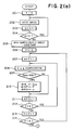
- the value of a parameter k is set at (0) (Step 201).
- An image is subsequently input from the read means 7 (Step 202), with the value of k incremented by one (Step 203), and it is determined if the value of k exceeds 5 (Step 204). In other words, the image at Step 202 is input five times.
- a sufficiently great constant is set at a parameter MIN (Step 205) and (0) is set at a parameter p (Step 206), whereas a parameter q is set at p + 1 (Step 207), whereby S p,q is computed as mentioned above (Step 208).
- Step 209 Whether S p,q is smaller than the parameter MIN is determined (Step 209) and, if it is smaller, S p,q, p and q are set at MIN, MINP and MINQ, respectively (Step 210).
- Step 211 The value of q is subsequently incremented by one (Step 211) and whether the value of q exceeds 6 is determined (Step 212). If the value of q is not greater than 6, the procedure is returned to Step 208, whereas if q is not smaller than 6, the value of p is incremented by one (Step 213).
- Step 214 Whether the value of p exceeds 5 is subsequently determined (Step 214) and, if it is not greater than 5, the procedure is returned to Step 207, whereas if it is not smaller than 5, whether MIN is smaller than St is determined (Step 215).
- St is a preset threshold value.
- FMINP is selected as a registered fingerprint and its distinct features are registered (Step 216). Selection of either FMINP or FMINQ is optional.
- F1- and F3-related functions of evaluation are separately computed so as to select optimum one of F1 and F3 by selecting what has a smaller value.
- the determination is given to the absence of a fingerprint to be registered or difficulty in making selection and inputting is demanded again.
- a candidate is input a plurality of times when physical features such as a fingerprint, etc. are registered and any given two cases are combined and then the combination is subjected to the same processing as what has been applied at the time of identification.
- the functions of evaluation are subsequently computed to estimate fingerprints obtained in poor input condition so that only the good fingerprint can be registered. This results in improvement of identifying accuracy.
- fingerprints as physical features, the length between joints of fingers, the sum obtained by adding up pixel values in the direction perpendicular to the longitudinal direction of the finger, palm prints, voiceprints, retinal patterns, etc.
- Fig. 4 is a block diagram illustrating the configuration of an apparatus for identifying an individual.
- the apparatus for identifying an individual comprises a prismatic right-angled equilateral prism 1 for obtaining a finger image from the difference between the contact and noncontact of a finger 9 placed thereon in parallel to the axial direction therewith, an illuminating means 3 for irradiating the right-angled equilateral prism 1, a television camera 5 for converting the finger image thus obtained into an electrical signal, an A/D converter 25 for converting the electrical signal into digital quantity, an image memory 29 for storing the digital finger image obtained by the A/D converter 25, a control unit 23 forming a nucleus of processing such as identification, and a read/write unit 27 for writing the added-up signal of each person who is identified to an IC card 33 and reading data from the IC card 33.
- a host machine 31 controls switching of a door and sounding of an alarm buzzer in accordance with the signal from the control unit 23. What is controlled by the host machine 33 varies with the security system to which this apparatus for identifying an individual is applied.
- Fig. 6 shows a flowchart of registration.
- the finger is placed on the surface of the prism in such a manner as to satisfy the relation between the finger and the prism as shown in Fig. 5.
- the prism is illuminated from the AA′ B′ B side and photographed from the AA′ C′ C side to obtain a finger image (Step 1801).
- An added-up signal is extracted by adding up the densities of the finger image in the direction perpendicular to the longitudinal direction of the finger (Step 1802). Subsequently, the added-up signal is registered in a dictionary (IC card 33) (Step 1803).
- Fig. 7 shows a flowchart of identification.
- the inputting of the finger image and the extraction of the added-up signal in Steps 1091 and 1902 follow the same process as that in the case of registration.
- the added-up signal preregistered in the dictionary is read out (Step 1903) and the added-up signal read from the dictionary is put in correct alignment with what is obtained from the input image (Step 1904).
- S(m) represents a parameter indicating consistency of A(i+m) and Ad(i), i.e., the smaller the value of S(m), the greater the consistency.
- the correct alignment is deemed complete at the position of M where the value of S(m) is minimized while making m change within a predetermined range; the then value of S(M) is made the result of identification (Step 1905).
- Step 1906 The resulting decision is sent to the host machine 31 (Step 1907), where processing is conducted in accordance with the results of decision.
- the prism is illuminated from the AA′ B′ B side in Fig. 5, it may be illuminated from the AA′ C′ C side used for photographing.
- the added-up signal obtained by adding up the densities of the finger image in the direction perpendicular to the longitudinal direction of the finger, the length of the portion partitioned with the joint of the finger, the length of the finger, etc.
Landscapes
- Engineering & Computer Science (AREA)
- Health & Medical Sciences (AREA)
- Life Sciences & Earth Sciences (AREA)
- Physics & Mathematics (AREA)
- Human Computer Interaction (AREA)
- General Physics & Mathematics (AREA)
- Animal Behavior & Ethology (AREA)
- Public Health (AREA)
- Medical Informatics (AREA)
- Molecular Biology (AREA)
- Surgery (AREA)
- Pathology (AREA)
- General Health & Medical Sciences (AREA)
- Heart & Thoracic Surgery (AREA)
- Veterinary Medicine (AREA)
- Biophysics (AREA)
- Biomedical Technology (AREA)
- Multimedia (AREA)
- Theoretical Computer Science (AREA)
- Collating Specific Patterns (AREA)
Applications Claiming Priority (2)
| Application Number | Priority Date | Filing Date | Title |
|---|---|---|---|
| JP330918/88 | 1988-12-29 | ||
| JP63330918A JPH02178780A (ja) | 1988-12-29 | 1988-12-29 | 個人特徴登録装置および個人認証装置 |
Publications (1)
| Publication Number | Publication Date |
|---|---|
| EP0376434A2 true EP0376434A2 (de) | 1990-07-04 |
Family
ID=18237922
Family Applications (1)
| Application Number | Title | Priority Date | Filing Date |
|---|---|---|---|
| EP89307210A Withdrawn EP0376434A2 (de) | 1988-12-29 | 1989-07-17 | Gerät zum Erfassen persönlicher Merkmale und zur Identifizierung von Personen |
Country Status (2)
| Country | Link |
|---|---|
| EP (1) | EP0376434A2 (de) |
| JP (1) | JPH02178780A (de) |
Families Citing this family (1)
| Publication number | Priority date | Publication date | Assignee | Title |
|---|---|---|---|---|
| JP4477258B2 (ja) * | 2001-03-30 | 2010-06-09 | セコム株式会社 | 指紋照合装置 |
-
1988
- 1988-12-29 JP JP63330918A patent/JPH02178780A/ja active Pending
-
1989
- 1989-07-17 EP EP89307210A patent/EP0376434A2/de not_active Withdrawn
Also Published As
| Publication number | Publication date |
|---|---|
| JPH02178780A (ja) | 1990-07-11 |
Similar Documents
| Publication | Publication Date | Title |
|---|---|---|
| US5974163A (en) | Fingerprint classification system | |
| US4047154A (en) | Operator interactive pattern processing system | |
| US4805224A (en) | Pattern matching method and apparatus | |
| JP3065104B2 (ja) | 指紋一致装置 | |
| KR930002348B1 (ko) | 지문검증의 미뉴시어(minutia) 데이타 추출 | |
| US4151512A (en) | Automatic pattern processing system | |
| JP3975248B2 (ja) | ニューラルネットワーク分類を使用する生物測定認識 | |
| EP1183638B1 (de) | Verfahren und vorrichtung zur erzeugung eines zusammengesetzten fingerabdruckbildes | |
| EP0470530A2 (de) | Verfahren zur Prüfung von Fingerabdrücken | |
| EP0043988B1 (de) | Verfahren zur Analyse gespeicherter Bildeinzelheiten | |
| JP2001510921A (ja) | 被験者のアイデンティティーを自動的に検証するためのシステム及び方法 | |
| GB2050026A (en) | Device for extracting a density as one of a number of pattern features extracted for each feature point of a streaked pattern | |
| US7035441B2 (en) | Check for fingerprints | |
| US5261008A (en) | Fingerprint verification method | |
| US7133542B2 (en) | Fingerprint verification device and fingerprint verification method | |
| EP0715275B1 (de) | Automatisches Fingerabdruckidentifizierungssystem mit Verfahren und Vorrichtung zum Vergleichen von Fingerabdrücken | |
| US5995641A (en) | Fingerprint identification device and method of using same | |
| US6961738B1 (en) | Information processing device and information processing method using fingerprint identification | |
| EP1150608B1 (de) | System und verfahren zur überprüfung von fingerabdrücken | |
| EP0376434A2 (de) | Gerät zum Erfassen persönlicher Merkmale und zur Identifizierung von Personen | |
| US20060120578A1 (en) | Minutiae matching | |
| US6275601B1 (en) | Fingerprinting judging method | |
| EP1295242B1 (de) | Prüfung von fingerabdrücken | |
| JP2866461B2 (ja) | 指紋照合装置 | |
| EP0347671B1 (de) | Gerät zum Fingervergleichen und Bildmusterverarbeitung |
Legal Events
| Date | Code | Title | Description |
|---|---|---|---|
| PUAI | Public reference made under article 153(3) epc to a published international application that has entered the european phase |
Free format text: ORIGINAL CODE: 0009012 |
|
| 17P | Request for examination filed |
Effective date: 19890802 |
|
| AK | Designated contracting states |
Kind code of ref document: A2 Designated state(s): DE FR GB |
|
| STAA | Information on the status of an ep patent application or granted ep patent |
Free format text: STATUS: THE APPLICATION HAS BEEN WITHDRAWN |
|
| 18W | Application withdrawn |
Withdrawal date: 19910515 |
|
| R18W | Application withdrawn (corrected) |
Effective date: 19910515 |