EP0376580A2 - Procédé pour la mesure acoustique de l'épaisseur d'éléments tubulaires - Google Patents
Procédé pour la mesure acoustique de l'épaisseur d'éléments tubulaires Download PDFInfo
- Publication number
- EP0376580A2 EP0376580A2 EP89313256A EP89313256A EP0376580A2 EP 0376580 A2 EP0376580 A2 EP 0376580A2 EP 89313256 A EP89313256 A EP 89313256A EP 89313256 A EP89313256 A EP 89313256A EP 0376580 A2 EP0376580 A2 EP 0376580A2
- Authority
- EP
- European Patent Office
- Prior art keywords
- tubular goods
- transducer
- casing
- investigated
- wall thickness
- Prior art date
- Legal status (The legal status is an assumption and is not a legal conclusion. Google has not performed a legal analysis and makes no representation as to the accuracy of the status listed.)
- Granted
Links
Images



Classifications
-
- G—PHYSICS
- G01—MEASURING; TESTING
- G01B—MEASURING LENGTH, THICKNESS OR SIMILAR LINEAR DIMENSIONS; MEASURING ANGLES; MEASURING AREAS; MEASURING IRREGULARITIES OF SURFACES OR CONTOURS
- G01B17/00—Measuring arrangements characterised by the use of infrasonic, sonic or ultrasonic vibrations
- G01B17/02—Measuring arrangements characterised by the use of infrasonic, sonic or ultrasonic vibrations for measuring thickness
-
- E—FIXED CONSTRUCTIONS
- E21—EARTH OR ROCK DRILLING; MINING
- E21B—EARTH OR ROCK DRILLING; OBTAINING OIL, GAS, WATER, SOLUBLE OR MELTABLE MATERIALS OR A SLURRY OF MINERALS FROM WELLS
- E21B47/00—Survey of boreholes or wells
- E21B47/006—Detection of corrosion or deposition of substances
-
- E—FIXED CONSTRUCTIONS
- E21—EARTH OR ROCK DRILLING; MINING
- E21B—EARTH OR ROCK DRILLING; OBTAINING OIL, GAS, WATER, SOLUBLE OR MELTABLE MATERIALS OR A SLURRY OF MINERALS FROM WELLS
- E21B47/00—Survey of boreholes or wells
- E21B47/08—Measuring diameters or related dimensions at the borehole
- E21B47/085—Measuring diameters or related dimensions at the borehole using radiant means, e.g. acoustic, radioactive or electromagnetic
-
- G—PHYSICS
- G01—MEASURING; TESTING
- G01V—GEOPHYSICS; GRAVITATIONAL MEASUREMENTS; DETECTING MASSES OR OBJECTS; TAGS
- G01V1/00—Seismology; Seismic or acoustic prospecting or detecting
- G01V1/40—Seismology; Seismic or acoustic prospecting or detecting specially adapted for well-logging
- G01V1/44—Seismology; Seismic or acoustic prospecting or detecting specially adapted for well-logging using generators and receivers in the same well
- G01V1/48—Processing data
- G01V1/50—Analysing data
Definitions
- the present invention relates to methods for acoustically measuring wall thickness of tubular goods such as well casing, production tubing, pipelines and the like, wherein the presence of corrosion on the tubular goods can be determined.
- casing In oil and natural gas wells, casing is set into the well borehole. In the borehole, the casing is subjected to corrosive elements which act on the casing by reducing the casing wall thickness. Cement, which has been forced into the annulus between the casing and the surrounding strata, protects the outer surface of the casing from corrosion. But occasionally the bond between the cement and the casing is unsatisfactory, wherein the outer surface of the casing is exposed to corrosive elements. Furthermore, casing is typically cemented only for portions of its length, leaving exposed portions.
- Corrosion and wear reduces the wall thickness of the casing, so by measuring the wall thickness, the presence or absence of corrosion can be inferred. Once corrosion has been detected on the casing, the situation can be evaluated and a decision can be made on whether or not to take corrective action, which corrective action is time consuming and expensive. In order to properly evaluate whether to take corrective action, the wall thickness of the corroded area, the extent of corrosion, and the location of the corrosion are factors which are considered.
- U.S. Pat. No. 4,255,798 discloses an ultrasonic logging apparatus for evaluating the bond between the cement and the casing.
- the apparatus also determines the wall thickness of the casing for corrosion detection purposes.
- One version of the logging apparatus utilizes a single fixed transducer and a rotating reflector.
- the transducer has a bandwidth of 300 KHz - 600 KHz, in order to excite the fundamental resonance of the casing wall and determine wall thickness.
- the relatively low bandwidth limits the resolution of the logging apparatus in determining casing wall thickness. Walls thinner than about 5mm are unresolvable. It is frequently desired to resolve thinner walls.
- the presence of the acoustical window in the path of the acoustic return causes distortion of the acoustic return, further limiting the resolution.
- the acoustical window could be impedance matched to reduce distortion, however varying conditions downhole, including mud weights and temperatures, make impedance matching of the acoustic return impractical.
- the method of the present invention provides an acoustical transducer means inside of the tubular goods which are to be investigated.
- the transducer means has a resonant frequency greater than 1MHz and is directly exposed to fluids in the investigated tubular goods.
- the transducer means is rotatable so as to scan 360 degrees of the circumference of the investigated tubular goods.
- the transducer means is excited to generate an acoustic waveform, which is directed to a portion of the investigated tubular goods.
- the transducer means then receives the resulting acoustic return.
- the acoustic return includes a reverberation portion which occurs as a result of the generated acoustic waveform reverberating inside of the investigated tubular goods portion.
- the reverberation portion is selected from the acoustic return, and the harmonic frequency content of the reverberation portion is determined.
- the frequency difference between two adjacent harmonic frequencies is determined and the wall thickness of the investigated portion is determined from the
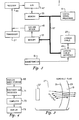
- FIGs. 1 and 2 there is shown a schematic longitudinal cross-sectional view of a cased well borehole 11, showing an ultrasonic logging apparatus 13 located therein, and supporting surface equipment 15, with which the method of the present invention, in accordance with a preferred embodiment, can be practiced.
- Both corrosion 28A and wear 28B reduce the wall thickness of the casing 19.
- the logging apparatus 13 and the method of the present invention measure wall thickness, from which the presence of corrosion or wear can be inferred.
- 162,771 filed March 1, 1988 which is owned by the assignee of the present invention, shows and describes a logging apparatus having a rotatable transducer portion and an exposed transducer, which is essentially identical to the logging apparatus shown and described herein.
- the disclosure of U.S. patent application Serial No. 162,771, filed March 1, 1988 is incorporated by reference into this disclosure.
- the transducer 37 can scan the entire circumference of the casing wall.
- the logging apparatus is centered along the longitudinal axis of the casing by centralizers 39.
- the transducer 37 generates an acoustic waveform which is directed to the casing wall 19.
- the interaction of the generated acoustic waveform with the casing wall produces an acoustic return.
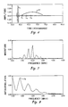
- the acoustic return is made up of a reflection portion E O , where the generated acoustic waveform is reflected off of the inner surface 21 of the casing wall, and a reverberation portion E1,E2,E3 ..., where the generated acoustic waveform reverberates inside of the casing wall between the inner and outer surfaces 21,23.
- the surface equipment 15 includes a logging cable interface 59, similar to the downhole logging cable interface 49.
- the data received from the logging apparatus 13 is sent to a receiver 61 from the logging cable interface 59, where it is filtered and amplified.
- the receiver 61 then sends the data to the analog mass storage unit 63, where the data is stored to await subsequent processing.
- the analog mass storage unit 63 can be, for example, a tape unit.
- the receiver 61 also sends the data to an amplitude sample and hold unit 65, so that the amplitude of the acoustic return can be monitored on the display 67 by an operator.
- the display 67 can also display an entire acoustic return.
- the next step involves taking the fast Fourier transform of the windowed time series, in order to obtain the frequency spectrum of the time series.
- the magnitude spectrum (see Fig. 7) is determined from the frequency spectrum by squaring the complex time series of the frequency spectrum and then determining the square root of the real portion of the squared complex time series.
- the power spectrum could be used, which is determined from the real portion of the squared complex time series.
- the magnitude spectrum is filtered by excluding time samples which lie outside of the transducer bandwidth (about 1.0MHz to 2.7MHz in Fig. 7).
- An alternative method for finding the frequency difference between harmonic frequencies can be used in lieu of autocorrelation.
- the digitized acoustic return time series is first squared. Then, the frequency spectrum is determined from the squared time series. Before squaring the time series, the time series is filtered to reduce noise.
- processing equipment can be brought on-site to the borehole to allow processing.
- the downhole electronics portion can be modified to allow downhole or real-time processing.
Landscapes
- Physics & Mathematics (AREA)
- Life Sciences & Earth Sciences (AREA)
- Engineering & Computer Science (AREA)
- Geology (AREA)
- Mining & Mineral Resources (AREA)
- Environmental & Geological Engineering (AREA)
- Geophysics (AREA)
- General Life Sciences & Earth Sciences (AREA)
- General Physics & Mathematics (AREA)
- Fluid Mechanics (AREA)
- Geochemistry & Mineralogy (AREA)
- Electromagnetism (AREA)
- Acoustics & Sound (AREA)
- Remote Sensing (AREA)
- Length Measuring Devices Characterised By Use Of Acoustic Means (AREA)
- Geophysics And Detection Of Objects (AREA)
Applications Claiming Priority (2)
| Application Number | Priority Date | Filing Date | Title |
|---|---|---|---|
| US07/291,684 US4912683A (en) | 1988-12-29 | 1988-12-29 | Method for acoustically measuring wall thickness of tubular goods |
| US291684 | 1988-12-29 |
Publications (3)
| Publication Number | Publication Date |
|---|---|
| EP0376580A2 true EP0376580A2 (fr) | 1990-07-04 |
| EP0376580A3 EP0376580A3 (fr) | 1991-09-04 |
| EP0376580B1 EP0376580B1 (fr) | 1993-08-18 |
Family
ID=23121381
Family Applications (1)
| Application Number | Title | Priority Date | Filing Date |
|---|---|---|---|
| EP89313256A Expired - Lifetime EP0376580B1 (fr) | 1988-12-29 | 1989-12-19 | Procédé pour la mesure acoustique de l'épaisseur d'éléments tubulaires |
Country Status (3)
| Country | Link |
|---|---|
| US (1) | US4912683A (fr) |
| EP (1) | EP0376580B1 (fr) |
| CA (1) | CA2005553A1 (fr) |
Cited By (1)
| Publication number | Priority date | Publication date | Assignee | Title |
|---|---|---|---|---|
| RU2614193C1 (ru) * | 2015-12-10 | 2017-03-23 | Открытое акционерное общество НПФ "Геофизика" (ОАО НПФ "Геофизика") | Скважинный акустический сканер |
Families Citing this family (31)
| Publication number | Priority date | Publication date | Assignee | Title |
|---|---|---|---|---|
| US5072388A (en) * | 1990-01-31 | 1991-12-10 | Union Oil Company Of California | Lined casing inspection method |
| JPH05306923A (ja) * | 1992-04-30 | 1993-11-19 | Takenaka Komuten Co Ltd | 面の三次元計測方法及び計測装置 |
| US5358040A (en) * | 1992-07-17 | 1994-10-25 | The Kinley Corporation | Method and apparatus for running a mechanical roller arm centralizer through restricted well pipe |
| US5491668A (en) * | 1994-05-13 | 1996-02-13 | Western Atlas International, Inc. | Method for determining the thickness of a casing in a wellbore by signal processing pulse-echo data from an acoustic pulse-echo imaging tool |
| US5942687A (en) * | 1998-04-01 | 1999-08-24 | The United States Of America As Represented By The Secretary Of The Navy | Method and apparatus for in situ measurement of corrosion in filled tanks |
| GB9812465D0 (en) * | 1998-06-11 | 1998-08-05 | Abb Seatec Ltd | Pipeline monitoring systems |
| US6131659A (en) * | 1998-07-15 | 2000-10-17 | Saudi Arabian Oil Company | Downhole well corrosion monitoring apparatus and method |
| NO312567B2 (no) | 1999-05-27 | 2002-05-27 | Halfwave As | Fremgangsmate ved maling av materialtykkelsesfordeling |
| US6308562B1 (en) * | 1999-12-22 | 2001-10-30 | W-H Energy Systems, Inc. | Technique for signal detection using adaptive filtering in mud pulse telemetry |
| US6661737B2 (en) * | 2002-01-02 | 2003-12-09 | Halliburton Energy Services, Inc. | Acoustic logging tool having programmable source waveforms |
| US7082822B2 (en) * | 2002-04-05 | 2006-08-01 | Vetco Gray Inc. | Internal riser inspection device and methods of using same |
| WO2004081525A2 (fr) * | 2003-03-07 | 2004-09-23 | Technical Industries, Inc. | Procede d'inspection d'articles metalliques tubulaires |
| US20060067162A1 (en) * | 2004-09-29 | 2006-03-30 | Blankinship Thomas J | Ultrasonic cement scanner |
| US7656747B2 (en) * | 2005-07-22 | 2010-02-02 | Halliburton Energy Services, Inc. | Ultrasonic imaging in wells or tubulars |
| US20090151456A1 (en) * | 2007-12-18 | 2009-06-18 | Baker Hughes Incorporated | Downhole tool damage detection system and method |
| WO2009126888A2 (fr) * | 2008-04-10 | 2009-10-15 | Services Petroliers Schlumberger | Procédé pour caractériser une formation géologique traversée par un forage |
| US8725477B2 (en) * | 2008-04-10 | 2014-05-13 | Schlumberger Technology Corporation | Method to generate numerical pseudocores using borehole images, digital rock samples, and multi-point statistics |
| US9175559B2 (en) * | 2008-10-03 | 2015-11-03 | Schlumberger Technology Corporation | Identification of casing collars while drilling and post drilling using LWD and wireline measurements |
| US8311788B2 (en) | 2009-07-01 | 2012-11-13 | Schlumberger Technology Corporation | Method to quantify discrete pore shapes, volumes, and surface areas using confocal profilometry |
| US20120136577A1 (en) * | 2009-08-05 | 2012-05-31 | Dennis Edward Dria | Systems and methods for monitoring corrosion in a well |
| US7975541B2 (en) * | 2009-12-16 | 2011-07-12 | General Electric Company | Folding ultrasonic borehole imaging tool |
| US9328606B2 (en) * | 2011-01-06 | 2016-05-03 | Schlumberger Technology Corporation | Method and device to measure perforation tunnel dimensions |
| KR101541978B1 (ko) * | 2013-12-31 | 2015-08-04 | 한국원자력연구원 | 배관 감육 검사장치 및 검사방법 |
| JP6672810B2 (ja) * | 2016-01-13 | 2020-03-25 | 株式会社大林組 | 超音波孔壁測定器 |
| AU2016396055B2 (en) * | 2016-03-03 | 2022-12-08 | Halliburton Energy Services, Inc. | Casing thickness estimation by frequency correlation |
| US10174604B2 (en) * | 2016-05-24 | 2019-01-08 | Weatherford Technology Holdings, Llc | Ultrasonic cement and casing thickness evaluation |
| AU2017297405B2 (en) | 2016-07-12 | 2019-10-24 | U.S. Steel Tubular Products, Inc. | Methods and systems for measurement and inspection of tubular goods |
| WO2018194596A1 (fr) * | 2017-04-19 | 2018-10-25 | Halliburton Energy Services, Inc. | Système, procédé et dispositif de surveillance d'un paramètre en fond de trou |
| GB2599878B (en) * | 2019-07-02 | 2022-12-28 | Baker Hughes Oilfield Operations Llc | Method and apparatus for determining a tubular thickness using a pulse echo waveform signal |
| US11397081B2 (en) * | 2019-07-02 | 2022-07-26 | Baker Hughes Oilfield Operations Llc | Method and apparatus for determining a tubular thickness using a pulse echo waveform signal |
| US20250354480A1 (en) * | 2024-05-20 | 2025-11-20 | Baker Hughes Oilfield Operations Llc | Casing thickness determination from pulse-echo ultrasonic measurements |
Family Cites Families (9)
| Publication number | Priority date | Publication date | Assignee | Title |
|---|---|---|---|---|
| US2825044A (en) * | 1949-08-02 | 1958-02-25 | Peterson Glen | Method of and apparatus for investigating subterranean strata |
| US3369626A (en) * | 1965-10-23 | 1968-02-20 | Mobil Oil Corp | Methods of and apparatus for producing a visual record of physical conditions of materials traversed by a borehole |
| US4255798A (en) * | 1978-05-30 | 1981-03-10 | Schlumberger Technology Corp. | Method and apparatus for acoustically investigating a casing and cement bond in a borehole |
| EP0075997A3 (fr) * | 1981-09-25 | 1985-05-22 | Sigma Research, Inc. | Appareil de forage |
| US4587641A (en) * | 1984-02-07 | 1986-05-06 | Shell Oil Company | Downhole fracture analysis |
| US4733380A (en) * | 1984-12-26 | 1988-03-22 | Schlumberger Technology Corporation | Apparatus and method for acoustically investigating a casing set in a borehole |
| US4709357A (en) * | 1985-08-14 | 1987-11-24 | Gearhart Industries, Inc. | Method and apparatus for acoustically investigating a borehole casing cement bond |
| US4780858A (en) * | 1986-12-29 | 1988-10-25 | Shell Oil Company | Borehole televiewer mudcake monitor |
| FR2629586B1 (fr) * | 1988-03-30 | 1992-01-03 | Cezus Co Europ Zirconium | Procede de controle ultrasonore de l'epaisseur de placage d'un tube metallique, dispositif correspondant et application a des tubes en alliage de zr plaque |
-
1988
- 1988-12-29 US US07/291,684 patent/US4912683A/en not_active Expired - Lifetime
-
1989
- 1989-12-14 CA CA002005553A patent/CA2005553A1/fr not_active Abandoned
- 1989-12-19 EP EP89313256A patent/EP0376580B1/fr not_active Expired - Lifetime
Cited By (1)
| Publication number | Priority date | Publication date | Assignee | Title |
|---|---|---|---|---|
| RU2614193C1 (ru) * | 2015-12-10 | 2017-03-23 | Открытое акционерное общество НПФ "Геофизика" (ОАО НПФ "Геофизика") | Скважинный акустический сканер |
Also Published As
| Publication number | Publication date |
|---|---|
| US4912683A (en) | 1990-03-27 |
| EP0376580B1 (fr) | 1993-08-18 |
| EP0376580A3 (fr) | 1991-09-04 |
| CA2005553A1 (fr) | 1990-06-29 |
Similar Documents
| Publication | Publication Date | Title |
|---|---|---|
| EP0376580B1 (fr) | Procédé pour la mesure acoustique de l'épaisseur d'éléments tubulaires | |
| US5491668A (en) | Method for determining the thickness of a casing in a wellbore by signal processing pulse-echo data from an acoustic pulse-echo imaging tool | |
| US4255798A (en) | Method and apparatus for acoustically investigating a casing and cement bond in a borehole | |
| US5874676A (en) | Method and apparatus for acoustically investigating a casing with a swept frequency pulse | |
| US9645269B2 (en) | Ultrasonic imaging in wells or tubulars | |
| US4928269A (en) | Determining impedance of material behind a casing in a borehole | |
| EP1040251B1 (fr) | Methode pour determiner l'impedance auto-calibree de la cimentation du tubage | |
| US4685092A (en) | Method and apparatus for the acoustic inspection of a borehole fitted with casing | |
| US5644550A (en) | Method for logging behind casing | |
| US20040095847A1 (en) | Acoustic devices to measure ultrasound velocity in drilling mud | |
| US4703427A (en) | Method for evaluating the quality of cement surrounding the casing of a borehole | |
| US10358905B2 (en) | Ultrasonic logging methods and apparatus for measuring cement and casing properties using acoustic echoes | |
| US7755973B2 (en) | Ultrasonic logging methods and apparatus for automatically calibrating measures of acoustic impedance of cement and other materials behind casing | |
| CN1950720B (zh) | 一种地层地震勘测方法 | |
| EP0513718A2 (fr) | Dispositif de détection de signaux pour téléviseur de puits | |
| CA1129066A (fr) | Methode et dispositif acoustiques d'examen d'un cuvelage, et raccord de cuvelage cimente dans un forage | |
| US4930109A (en) | Method and apparatus of measuring ultrasonic time travel information obtained from logging operations in a well borehole | |
| GB2308190A (en) | Acoustic reflection borehole logging apparatus | |
| WO2022011294A1 (fr) | Appareil de diagraphie et son procédé d'utilisation | |
| US4899144A (en) | Method of transmitting ultrasonic amplitude & time travel information over a logging cable | |
| Katahara et al. | Detection Of External Pipe Defects With A Modified Borehole Televiewer |
Legal Events
| Date | Code | Title | Description |
|---|---|---|---|
| PUAI | Public reference made under article 153(3) epc to a published international application that has entered the european phase |
Free format text: ORIGINAL CODE: 0009012 |
|
| AK | Designated contracting states |
Kind code of ref document: A2 Designated state(s): FR GB |
|
| 17P | Request for examination filed |
Effective date: 19901220 |
|
| PUAL | Search report despatched |
Free format text: ORIGINAL CODE: 0009013 |
|
| AK | Designated contracting states |
Kind code of ref document: A3 Designated state(s): FR GB |
|
| 17Q | First examination report despatched |
Effective date: 19921123 |
|
| GRAA | (expected) grant |
Free format text: ORIGINAL CODE: 0009210 |
|
| AK | Designated contracting states |
Kind code of ref document: B1 Designated state(s): FR GB |
|
| ET | Fr: translation filed | ||
| PGFP | Annual fee paid to national office [announced via postgrant information from national office to epo] |
Ref country code: GB Payment date: 19931203 Year of fee payment: 5 |
|
| PGFP | Annual fee paid to national office [announced via postgrant information from national office to epo] |
Ref country code: FR Payment date: 19931221 Year of fee payment: 5 |
|
| PLBE | No opposition filed within time limit |
Free format text: ORIGINAL CODE: 0009261 |
|
| STAA | Information on the status of an ep patent application or granted ep patent |
Free format text: STATUS: NO OPPOSITION FILED WITHIN TIME LIMIT |
|
| 26N | No opposition filed | ||
| PG25 | Lapsed in a contracting state [announced via postgrant information from national office to epo] |
Ref country code: GB Effective date: 19941219 |
|
| GBPC | Gb: european patent ceased through non-payment of renewal fee |
Effective date: 19941219 |
|
| PG25 | Lapsed in a contracting state [announced via postgrant information from national office to epo] |
Ref country code: FR Effective date: 19950831 |
|
| REG | Reference to a national code |
Ref country code: FR Ref legal event code: ST |