EP0376754A2 - Blattabtrennvorrichtung - Google Patents
Blattabtrennvorrichtung Download PDFInfo
- Publication number
- EP0376754A2 EP0376754A2 EP89313706A EP89313706A EP0376754A2 EP 0376754 A2 EP0376754 A2 EP 0376754A2 EP 89313706 A EP89313706 A EP 89313706A EP 89313706 A EP89313706 A EP 89313706A EP 0376754 A2 EP0376754 A2 EP 0376754A2
- Authority
- EP
- European Patent Office
- Prior art keywords
- sheet
- roller
- rollers
- feed
- paper sheet
- Prior art date
- Legal status (The legal status is an assumption and is not a legal conclusion. Google has not performed a legal analysis and makes no representation as to the accuracy of the status listed.)
- Granted
Links
Images


Classifications
-
- B—PERFORMING OPERATIONS; TRANSPORTING
- B26—HAND CUTTING TOOLS; CUTTING; SEVERING
- B26D—CUTTING; DETAILS COMMON TO MACHINES FOR PERFORATING, PUNCHING, CUTTING-OUT, STAMPING-OUT OR SEVERING
- B26D1/00—Cutting through work characterised by the nature or movement of the cutting member or particular materials not otherwise provided for; Apparatus or machines therefor; Cutting members therefor
- B26D1/01—Cutting through work characterised by the nature or movement of the cutting member or particular materials not otherwise provided for; Apparatus or machines therefor; Cutting members therefor involving a cutting member which does not travel with the work
- B26D1/02—Cutting through work characterised by the nature or movement of the cutting member or particular materials not otherwise provided for; Apparatus or machines therefor; Cutting members therefor involving a cutting member which does not travel with the work having a stationary cutting member
-
- B—PERFORMING OPERATIONS; TRANSPORTING
- B65—CONVEYING; PACKING; STORING; HANDLING THIN OR FILAMENTARY MATERIAL
- B65H—HANDLING THIN OR FILAMENTARY MATERIAL, e.g. SHEETS, WEBS, CABLES
- B65H35/00—Delivering articles from cutting or line-perforating machines; Article or web delivery apparatus incorporating cutting or line-perforating devices, e.g. adhesive tape dispensers
- B65H35/10—Delivering articles from cutting or line-perforating machines; Article or web delivery apparatus incorporating cutting or line-perforating devices, e.g. adhesive tape dispensers from or with devices for breaking partially-cut or perforated webs, e.g. bursters
-
- Y—GENERAL TAGGING OF NEW TECHNOLOGICAL DEVELOPMENTS; GENERAL TAGGING OF CROSS-SECTIONAL TECHNOLOGIES SPANNING OVER SEVERAL SECTIONS OF THE IPC; TECHNICAL SUBJECTS COVERED BY FORMER USPC CROSS-REFERENCE ART COLLECTIONS [XRACs] AND DIGESTS
- Y10—TECHNICAL SUBJECTS COVERED BY FORMER USPC
- Y10T—TECHNICAL SUBJECTS COVERED BY FORMER US CLASSIFICATION
- Y10T225/00—Severing by tearing or breaking
- Y10T225/30—Breaking or tearing apparatus
- Y10T225/35—Work-parting pullers [bursters]
-
- Y—GENERAL TAGGING OF NEW TECHNOLOGICAL DEVELOPMENTS; GENERAL TAGGING OF CROSS-SECTIONAL TECHNOLOGIES SPANNING OVER SEVERAL SECTIONS OF THE IPC; TECHNICAL SUBJECTS COVERED BY FORMER USPC CROSS-REFERENCE ART COLLECTIONS [XRACs] AND DIGESTS
- Y10—TECHNICAL SUBJECTS COVERED BY FORMER USPC
- Y10T—TECHNICAL SUBJECTS COVERED BY FORMER US CLASSIFICATION
- Y10T83/00—Cutting
- Y10T83/525—Operation controlled by detector means responsive to work
- Y10T83/533—With photo-electric work-sensing means
Definitions
- the present invention relates to a continuous paper sheet tearing-up or cutting apparatus provided with a pair of a upper infeed or feed-in roller and a lower infeed or feed-in roller, and another pair of a upper roller and a lower roller rotating at a rotary speed higher than that of the former pair of rollers, so that the difference between the feeding or advancing speeds of the continuous paper sheet fed through the former roller pair of a low-speed and the latter pair of a high-speed tears the paper sheet.
- the continuous paper sheet is always held or nipped by a pair of upper feed-in roller and a lower feed-in roller, and another pair of upper and lower high speed rollers.
- Such conventional apparatus of the second kind holds or nips the continuous paper sheet only at the instant of tearing-up it by means of both the pair of rollers.
- the pair of the upper and lower feed-in rollers always holds the continuous paper sheet and the another pair of high speed upper and lower rollers nips the sheet only at the instant of tearing-up operation.
- the inventor improved the conventional continuous paper tearing-up apparatus of the second kind and also the modification of the apparatus.
- the gaps between the upper rollers and the lower rollers correspondingly increase or decrease, so that it has been difficult to tear-up the continuous paper sheet through the right or precise position of the sheet, even when the separation function of both pairs of rollers is correctly carried out.
- the tearing-up size of the continuous paper sheet is measured and the sheet is set uncorrectly on the sheet measurement mechanism, it is impossible to precisely measure the tearing-up size. If the tearing-up position of the paper sheet is determined according to the wrong measurement result, any precise control of the aparting functions of each pair of rollers doesn't enable to tear-up the paper sheet from its correct position or part.
- the present invention has been accomplished to solve the shortcomings resided in the conventional continuous paper sheet tearing-up apparatus of the second kind. So, it is the first purpose of the present invention is to provide a coninuous paper sheet tearing-up apparatus for precisely measuring the tearing-up size of the continous paper sheet and controlling the aparting operation of the pair of the upper and the lower feed-in rollers and the other pair of the upper and the lower high speed rollers.
- It is the second purpose of the present invention is to provide a continuous paper sheet tearing-up apparatus enabling to set the gaps between the upper and the lower feed-in rollers, and between the upper and the lower high speed rollers at the instant of tearing-up.
- It is the third purpose is to provide a continuous paper sheet tearing-up apparatus for correcting any error, if any, in the tearing-up size measured of the sheet paper in order to tear-up the continuous paper sheet at its correct position.
- It is the fourth purpose is to provide a continuous paper sheet tearing-up apparatus which is made permitted to measure the tearing-up size only when the paper sheet is correctly set at its predetermined position.
- It is the fifth purpose is to provide a compact continuous paper sheet tearing-up apparatus enabling to carry up a correct tearing-up operation.
- the continuous paper sheet tearing-up apparatus has a pair of the feed-in rollers and another pair of high speed rollers, both the pairs being separated along the horizontal direction and the rollers respectively in the same pair being arranged so as to approach each other and apart from the opponent along their vertical direction, a blade situated between the pair of feed-in rollers and another pair of high speed rollers, a paper sheet size measurement device for measuring at least the long side of the folded continuous paper sheet through, for example, an optical means, and an approach timing control device for controlling according to the measurement result a timing of the sheet nipping operations of the pair of feed-in rollers and another pair of high speed rollers along the vertical direction, and the approaching or nipping movements, respectively of both the pair of feed-in rollers and another pair of high speed rollers at the tearing-up time of the continuous paper sheet give a difference in the paper transfer speed and the blade is applied to the paper sheet so as to tear-up it at the same time.
- the high tearing-up precision of the paper sheet is attained by automatically measuring the long side or the length of the folded paper sheet and controlling the nipping timing of the pair of the upper and the lower feed-in rollers and another pair of the upper and the lower high speed rollers approaching vertically.
- the continuous paper sheet tearing-up apparatus has a pair of feed-in rollers, another pair of high speed rollers, a blade, an input means for manually or automatically using various sensors inputting the information of a thickness of the continuous paper sheet to be torn, and a nipping-gap control means for controlling the vertical distances between the pair of feed-in rollers and another pair of high speed rollers.
- a nipping-gap control means for controlling the vertical distances between the pair of feed-in rollers and another pair of high speed rollers.
- the continuous paper sheet tearing-up apparatus provides with a pair of the upper and the lower feed-in rollers rotating at the predetermined speed, another pair of the upper and the lower high speed rollers rotating at the speed higher than the predetermined speed, a sheet size measurement device for measuring at least the length of the paper sheet folded in a shape of zig-zag, a standard size setting portion for setting previously a plurality of standard sizes of the continuous paper sheet, and a size adjusting portion for correcting the size of the paper sheet measured by the sheet size measurement device to a standard size nearing to and on the basis of the standard size set by the standard size setting portion so as to set the tearing-up position of the continuous paper sheet to be torn by the pairs of the feed-in rollers and the high speed rollers based on the standard size of the paper sheet corrected in the size adjusting portion.
- the error can be corrected on the basis of the standard size previously inputted and the tearing-up position of the continuous paper sheet is set enabling to tear-up the sheet always at the exact position.
- the continuous paper sheet tearing-up apparatus has a pair of the upper and the lower feed-in rollers, respectively rotating at the predetermined speed, a pair of the upper and the lower high speed rollers, respectively rotating at a speed higher than the predetermined one above, a sheet size measurement device for measuring at least the distance or length of the continuous paper sheet folded in a zig-zag and positioned on a stand of the paper sheet, a detecting device for dispatching a placing signal when the folded paper sheet is placed on the stand at the predetermined position, and a measurement control portion for issuing size measurement ordering signals to the sheet size measurement device, in order to set the tearing-up position of the continuous paper sheet torn by the pair of the feed-in rollers and another pair of high speed rollers based on the sheet size signals from the sheet size measurement device. It is noted that when the continuous paper sheet folded is not placed on the stand at the predetermined position, no measurement of the sheet throug
- the continuous paper sheet tearing-up apparatus has a pair of the upper and the lower feed-in rollers rotating at the predetermined speed and nipping the sheet at least at the tearing-up instant, a feeding portion for transferring or feeding the continuous paper sheet, a pair of the upper and the lower high speed rollers rotating at the speed higher than the pair of the feed-in rollers and approaching each other at the tearing instant so as to nip the continuous paper sheet running through the rollers in order to tear-up the paper sheet using the speed difference of the high speed rollers from the feed-in rollers, a sheet edge detection portion for detecting the front edge of sheet transferred to that position, a tearing-up size input portion, for example a sheet size measurement apparatus, for manually or automatically inputting the tearing-up size of the continuous paper sheet and a control means for controlling the approaching operation of the pair of the upper and the lower high speed rollers according to the signals from the sheet edge detection portion, a tearing-up size signal
- the continuous paper sheet tearing-up apparatus of the present invention has the feeding portion having a sheet transfer function, it is possible to transfer the continuous paper sheet without installation of the transfer device, such as a tractor mechanism and the like. Control of each high speed rollers carried out on the basis of a transfer length of the continuous paper sheet fed through the feeding portion and the tearing-up size enables the continuous paper sheet tearing-up apparatus to carry out a correct tearing-up operation.
- the continuous paper sheet 1 to be teared-up to the unit sheet 1a is placed on the placing stand 3 at its predetermined position.
- the paper sheet 1 is folded through the perforations for bending and tearing-up the sheet in a shape of zig-zag and placed on the stand 3.
- the stand has a sheet size measurement device therein for measuring the width and the length of the folded sheet, or these distance of the width and the length of the unit sheet 1a.
- the continuous paper sheet 1 has marginal portions 5 and 5 formed at the both sides along the longitudinal direction of the sheet, being bounded by tearing-up perforations 4 and 4. In the marginal portions, there are a plurality of marginal holes 6 and 6 separated uniformly along the axial direction of the sheet.
- the stand 3 has a ceiling plate 3a on which the continuous paper sheet 1 is placed. There are, on the ceiling plate 3a, a long light transparent plate 7 extending along the width direction of the continuous sheet and measuring the width of the unit paper sheet 1a, and another long light transparent or transmitting plate 8 extending along the direction perpendicular to the direction of the light transparent plate 7 and measuring the length or depth of the unit paper sheet 1a along its continuous or extending direction. As shown in Fig 4, at the position corresponding to the light transparent plate 7 formed in the ceiling plate 3a, a rotary shaft 11 rotatably supported on the support plates 9 and 10, respectively fixed in the stand 3 extends.
- a phototube 12 having a rotation preventor (not shown) is fixed to the rotary shaft 11.
- a driving motor 13 fixed thereto.
- a slit plate 14 fixed thereto.
- a slit direction device 15 fixed to a supporting plate 10.
- the mechanism or construction mentioned above measures the width of the unit sheet 1.
- a mechanism for measuring a depth of the unit sheet 1a is placed, which mechanism having a phototube 18 and is similar to that measuring the width of the unit sheet 1a as described above.
- the same reference numerals with affixes "a" are applied to the respective construction parts corresponding to the parts of the width measurement mechanism above and a detailed explanation for the depth measurement mechanism is omitted.
- the width and the depth of the unit sheet 1a are measured by rotation volumes of the rotary shafts 11 and 11a of each phototubes 12 and 18.
- the rotation volumes are changed to the passing number of slits of equal pitches of beams from the phototubes 12 and 18, and then the passing number is detected by the slit detection mechanisms 15 and 15a.
- the sheet size signal detected is sent to the size controlling portion of a CPU 19 through a measurement controll portion C shown in Fig 1.
- a sensor S1 for detecting the continuous paper sheet 1 correctly placed on the predetermined position of the ceiling plate 3a is installed at the position along a wall plate (not shown) of the continuous paper sheet treating apparatus.
- a pair of sensors S2 and S2 for detecting the continuous paper sheet 1 wrongly placed on the ceiling plate 3a are installed at these longitudinal ends of the light transmitting plate 7.
- the detection apparatus S consisting of the central sensor S1 and two side sensors S2 and S2 is adapted to dispatch a placement signal when the continuous paper sheet 1 is placed at the predetermined position. In consequence. the placement signal is issued when the sensor S1 is ON and these sensors S2 and S2 are OFF.
- a size measurement order signal is issued from the measurement control portion C to the sheet measurement size apparatus.
- a sheet size signal from the slit detection devices 15 and 15a of the sheet measurement size apparatus is sent to the size control portion through the measurement control portion C.
- the size control portion compares the inputted measurement value to the standard size set and sustained in the standard size setting portion in the CPU 19 in order to correct it to the nearest standard size.
- the standard size setting portion has the width standard sizes of the unit sheet 1a in the unit of 1/10 inch and the depth standard sizes of the unit sheet 1a in the unit of 1/2 inch. The number of the width and the depth standard sizes are suitably determined and set in the setting portion.
- the continuous paper sheet 1 placed on the stand 3 is pulled or drawn out upwardly and guided on a guide plate 49.
- the marginal holes 6 and 6 formed at both the margins of the paper sheet 1 are engaged with trancting pins of the tractor 20 driven by a main motor 21.
- the paper sheet 1 is fed rightwardly on the sheet of Fig 1.
- the transfer or feeding speed of the paper sheet 1 is detected through a detector 23 installed in the tractor encoder 22 for detecting the number of rotation of the tractor 20 and the detected speed signal is sent to the CPU 19.
- a slitter 24 installed near the rearward end of the tractor 20 cuts off the margins 5 and 5 from the sheet 1 through its perforations 4 and 4, the sheet 1 is further sent along the same direction, and it is supplied to a tearing-up apparatus.
- the two wheels of the tractor 20 are controlled or moved by a lunction of the gear 41 to which a driving force of the sub motor 40 is transferred and the distance between these wheels are determined.
- the slitter 24 is moved together with the tractor 20.
- the motor 40 is driven and controlled by a control signal from the CPU 19, which control signal being attained by correcting the resultant width distance of the unit sheet 1a measured by the sheet size measurement apparatus.
- the opposing distance between the wheels of the tractor 20 is set at that value narrower than the width of the continuous paper sheet 1 measured by the phototube 12 by 0.5 inch, so that the marginal holes 6 and 6 placed inside from the longitudinal edges of the paper sheet by 0.25 inch are matched to the tractor pins.
- a set of sheet thickness detectors 25a and 25b for detecting the sheet thickness according to the light transmitting volume at the three steps of "thin", “middle” and “thick” are placed opposedly along the vertical line sandwiching the traveling route of the continuous paper sheet 1, dispatching a detection signal to be sent to the CPU 19.
- These sheet thickness detectors 25a and 25b construct an input means for inputting information of the paper sheet thickness of the continuous paper sheet 1.
- a blade 28 to be applied to the perforations 2 extending along the depth direction (see Fig 6) so as to bent and tear-up the continuous paper sheet 1, and a sheet edge detector 29 of a high reflection type for detecting the front edges of the sheet.
- the detector 29 outputs detection signals to the CPU 19.
- each rotary shaft 30 and 31 of the lower feed-in roller 26b and the upper high speed roller 27a are supported eccentrcially by bearings 32 and 33.
- Rotary shafts (not shown), respectively installed at the centres of the bearings 32 and 33 are born rotatably at the machine frame (not shown).
- an endless belt 36 is wound around a driving plate 35 fixed to an output shaft of a motor 34 and these bearings 32 and 33.
- the pulse motor 34 is connected to the CPU 19 functioning or controlling the approach timing, and its output shaft rotates by the predetermined volume along the predetermined direction by a driving control signal according to the depth standard size corrected in the size control portion of the CPU 19. Accordingly, also the driving plate 35 rotates along the same direction and by the same volume as these of the output shaft. The rotation is transferred to respective bearings 32 and 33 through the endless belt 36. Owing to the rotation of the bearings 32 and 33 around shafts (not shown), the rotary shafts 30 and 31 rotate in an arc shape along the same direction.
- a stacker device for sequentially stacking the unit sheets 1a cut.
- This stacker device has an elevatable table 36 on which the unit paper sheets 1a are placed.
- a conveying guide belt 37 is placed at a suitable position, which belt having two thin belts (one belt is shown) running in parallel and along a circular route in order to pull-in the unit sheets 1a.
- the sheet pull-in speed of the thin belts in higher than the sheet push-out speed of the tearing-up apparatus.
- a stopper 39 movable along the advancing direction of the unit sheets and on which the front edges of the unit sheets 1a are hit, and a stacked sheet volume delecting divice 38 for detecting the position or level of the uppermost or top unit sheet 1a of the heap of unit sheets on the elevatable table 36 and issuing a detection signal for lowering the table 36 when the detected level becomes higher than the predetermined one to the CPU 19 are installed on the tearing-up apparatus as shown in Fig 10.
- the conveying guide belt 37 has a pair of driving rolls 50 on which the thin belt is wound and the rolls have projections on their peripheries, so that a part of the thin belt intermittently is pushed down by the projections.
- the conveying guide belt 37 can firmly engage with unit sheets 1 to convey it and the unit sheet 1a strikes with the stopper, so that the unit sheet 1a is always lightly and smoothly stacked on the elevatable table 36.
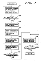
- the continuous sheet 1 is placed on the placement table 3 in a manner of the predetermined folded condition at the predetermined position of the table 3 and a measurement operation of the sheet size is carried out.
- the measurement operation is explained with reference to Fig 7, together with the control operation of the CPU 19.
- the sensors S1, S2, and S2 sense or detect the heaping position of the continuous sheet 1 determining that the position is the predetermined one or not (Step 101).
- a size measurement order signal is issued from the measurement control portion C and the driving motors 13 and 13a are driven.
- the rotary shafts 11 and 11a are driven in order to move phototubes 12 and 18 along respective rotary shafts 11 and 11a (Step 103).
- the moving or travelling volume or distance measured from the instant that light of the phototube 12 to be passed through the light transparent plate 7 is interrupted by the continuous paper sheet 1 to the instant that light of the phototube again passes through the light transparent plate 7 corresponds to the width of the continuous paper sheet 1.
- the number of slits corresponding to the moving distance above is counted in the slit detection apparatus 15 from the instant of interrupting the light to other instant of re-transmitting the light.
- the counted number is replaced by the moving distance of the phototube 12 and used as a width deterction signal which is outputted to the size control portion of the CPU 19 (Step 104).
- the size measurement portion of the CPU 19 compares the width detection signal to the width standard size previously set in the standard size setting portion in order to correct it to similar width standard size (Step 105).
- a width detection signal corresponding to, for example, 3.24 inch is issued
- the width standard size with a unit of 1/10 inch is set in the standard size setting portion, so that it is said the size of 3.24 inch is placed between 3.2 inch and 3.3 inch and it is corrected to 3.2 inch similar to 3.24.
- the CPU 19 sent a drive control signal based on or according to the corrected value to the motor 40 (Step 106) and the distance between the wheels of the tractor 20 is controlled through the gear 41 so as to be match to the width of the continuous paper sheet 1 (Step 107).
- the slit number corresponding to the moving distance from the movement starting instant to the light transmitting instant is counted from the movement starting instant to the light passing instant. Then, the counted number or the corresponding moving distance is added to the distance from the position of the phtotube 18 to the position of the edge of the continuous paper sheet 1 at its initial position. The resultant sum is outputted to the size control portion of the CPU 19 as a depth detection signal of the continuous sheet 1 (Step 104).
- the size control portion compares the depth detection signal to the depth standard size previously set in the standard size setting portion in order to correct it to the similar or nearest depth standard size (Step 105).
- a depth detection signal corresponding to 4.25 inch is outputted, because the depth standard size is set by units of 1/2 inch in the standard size setting portion, the size of 4.25 inch is said to be placed at the mid point between 4.0 inch and 4.5 inch. Raising the number, it is corrected to 4.5 inch.
- the CPU 19 sends a drive control signal according to the corrected number of 4.5 inch to a driving motor (not shown) for adjusting the position of the stopper 39 of the stacker device (Step 108) and the position of the stopper 39 is adjusted so as to fit to the depth of the unit sheet 1a (Step 109).
- the depth detection signal previously corrected is stored in a memory of the CPU 19.
- the continuous paper sheet 1 heaped on the stand 3 is pulled up and reachs the tractor 20 having two opposing wheels of a controlled separation distance through the guide plate 49.
- the marginal holes 6 and 6 of the continuous paper sheet 1 are engaged with the tractor pins planted on the tractor 20 and then the main motor 21 is driven.
- the continuous paper sheet 1 is transferred to the right on the sheet of Fig 1 and the marginal portions or margins 5 and 5 are cut off by the slitter 24 at the transit instant of the moving sheet.
- the transfer speed of the sheet 1 is detected by the detector 23 and the result is sent to the CPU 19.
- the thickness of the continuous paper sheet 1 detected when it passes through the sheet thickness detectors 25a and 26b and the result of the detection signal is sent to the CPU 19.
- the vertical gaps of the upper and the lower feed-in rollers 26a and 26b and of the upper and the lower high speed rollers 27a and 27b are controlled by the CPU 19 treating the detection signal.
- the gap controlling process of the CPU 19 will be described with reference to Fig 8 and Fig 9.
- the axis of abscissa of the graph in Fig 9 shows the time starting from the instant of the continuous sheet edge detection.
- the sheet thickness detectors 25a and 25b detect the thickness (Step 201).
- an on-off timing of the pulse motor 34 is set to a 12-pulse timing (Step 203).
- a drive signal is outputted to the pulse motor 34 at the instant earlier than the standard timing (in case of "middle” thickness) by a time of 2 pulses, which standard timing starts at the timing the sheet edge detection signal from the detector 29 inputs to the CPU 19.
- the standard timing in case of "middle" thickness corresponds to the sheet traveling or transfer speed and the depth of the unit sheet 1a.
- Another drive signal for returning the pulse motor stops at the instant later than the standard timing above by a time of 2 pulses. Consequently, the gap between the rollers at the instant the continuous sheet 1 reaches the upper and the lower rollers 26a, 26b and 27a, 27b is set to be narrower than the standard timing of the "middle" thickness.
- the on-off timing of the pulse motor 34 is set of a 10-pulse timing (Step 205) of the standard one.
- the CPU outputs a drive signal to the pulse motor 34 at the timing according to the depth of the unit sheet 1a and the sheet traveling speed.
- the standard gap of these upper and lower rollers equals to that obtained when the continuous paper sheet 1 reaches respective rollers 26a, 26b and 27a, 27b.
- Step 207 the on-off timing of the pulse motor 34 is set at a 8-pulse timing (Step 207).
- the 8-pulse timing it is apparent from Fig 9 that, starting at the instant the sheet edge detection signal from the sheet edge detector 29 inputs to the CPU 19, a drive signal is outputted from the CPU 19 to the pulse motor at the instant later than the standard timing (in case of "middle") according to the depth of the unit sheet 1a and the sheet traveling speed. While, the returning drive signal is stopped at the instant earlier than the standard timing by a time of 2 pulses. In consequence, the gap attained at the time the continuous sheet 1 reaches respective rollers 26a, 26b and 27a, 27b is set wider than that of the standard timing (in case of "middle").
- the thickness of the continuous paper sheet 1 is detected, then the front edge of the sheet is detected by the sheet edge detector 29, and information of the front edge detection signal inputs to the CPU 19.
- the CPU 19 receives the front edge detection signal, the CPU 19 outputs a drive signal to the pulse motor 34 at a suitable timing determined according to the traveling speed, the corrected depth detection signal, and the thickness detection signal, respectively inputted to the CPU. Consequently, when the paper sheet 1 reaches the tearing-up position suitable to the depth corrected, both gaps between respective pairs of the upper and the lower feed-in rollers 26a,26b of the upper and the lower high speed rollers 27a, 27b become suitable to the actual thickness of the traveling sheet.
- the perforations 2 through which the continuous sheet is bent and torn are tensed and so pulled as to be torn by functions of respective pairs of rollers have a blade 28 applied thereto and the continuous sheet 1 is cut into the unit sheets 1a.
- the unit paper sheets 1a cut are heapped one by one on the elevatable table 36 through the conveying guide belt 37.
- the position of the stopper 39 is already adjusted so as to be fitted to the depth of the unit sheets 1a, so that the sheet conveying motion to the table is done smoothly.
- the level of the top unit sheet 1a of the heap becomes higher than that of the predetermined position, it is detected by a sheet stack volume detector 38, the resultant detection signal is sent to the CPU 19, the elevatable table 36 downs by the determined height in order to carry out always a smooth stacking operation.
- Fig 10 shows another preferred embodiment of the continuous paper sheet tearing-up apparatus of the present invention, in which there is not tractor 20, and the transfer of the continuous paper sheet 1 is done by a feeding or in-feed portion having a sheet transfer function.
- the feeding portion includes a pair of the upper and the lower feed-in rollers, respectively apartable and approacheable along their vertical direction. Usually those opposed rollers are arranged with a gap of about 1 to 1.5 mm.
- the feeding rollers 56a and 56b respectively have three dents or concaves 42a, 42b, 42c, 43a, 43b and 43c formed thereon as shown in Fig 12 so as to be separated along the longitudinal directions of the rollers 56a and 56b.
- a pair of curved or inverted J-shaped oscillating arms 45a and 45b are attached or installed in the concaves 42a and 42b of the upper feed-in roller 56a.
- the oscillating arms 45a and 45b have two rotable transfer rolls 44a and 44b at their ends. Respective other ends of the curved oscillating arms 45a and 45b are oscillatably held by a supporting rod 46 fixed to a machine frame (not shown).
- the oscillating arms 45a and 45b are adapted to be pressed so as to osciallate clockwise on the sheet of Fig 11 due to a compression or contraction force of the springs 48a and 48b arranged between the fixing plate 47 attached to the machine frame and parts adjacent to both other end of the oscillating arms.
- the transfer rolls 44a and 44b supported at the ends of the oscillating arms rotatably contact with the outer periphery of the lower feed-in roller 56b.
- the continuous paper sheet 1 is not cut, it is transferred by the operation of the lower feed-in roller 56b and the transfer rolls 44a and 44b.
- respective transfer rolls 44a and 44b enter into the corresponding concaves 42a and 42b of the upper feed-in roller 56a against the compression forces of the springs 48a and 48b.
- a transferred volume of the continuous paper sheet 1 or a transfer speed of the sheets through the feeding portion is detected by the detector 52 installed in a feeding roller encoder 51 for detecting the rotation number of the feed-in roller 56a and the resultant speed detection signal is sent to the CPU 19.
- the feed-in rollers 56a, 56b and the high speed rollers 27a, 27b are driven by the main motor 21 through a driving force transmitting mechanism (not shown).
- any types of the continuous paper sheets 1 having margines 5 and 5 as described in the first embodiment and or not having them as these margines are cut off from the sheet may be used.
- the continuous paper sheet 1 has each marginal portions 5 and 5, they are transferred without using these marginal portions 5 and 5.
- the sheet size measurement device structures a tearing-up size inputting portion.
- the continuous sheet 1 is pulled up one by one or gradually, led to between the feed-in rollers 56a and 56b through the guide plate 49, and nipped between the transfer rolls 44a, 44b and the lower feed-in roller 26a. Then, the main motor 21 is driven to transfer the continuous paper sheet 1.
- the following operation of the apparatus is the same as that of the first embodiment and its explanation is omitted.
- the second embodiment of the present invention there is no need to install any transfer mechanism for the continuous sheet 1 particularly, so that it is possible advantageously to simplify the construction of the whole construction of the continuous paper sheet tearing-up apparatus and to make it compact. Also, it is possible to construct the feed-in rollers 56a and 56b so as to always hold or nip the continuous paper sheet 1. In the case above, there is no need to install the transfer rolls 49a and 49b. It is also possible to input a tearing-up size of the sheet by manual operations, such as button pressing and the like.
- the feeding portion provided with feed-in rollers 56a and 56b described in the preferred second embodiment above in place of the feed-in rollers 26a and 26b used in the first embodiment of the present invention.
- the sheet transferred volume through the feeding portion or the sheet travelling speed through the feeding portion are not detected through the rotation number of the feed-in rollers 56a and 56b and it is delected by using the detector 23 existed on the tractor encoder 22 so as to detect the rotation number of the tractor 20 having the same driving source as that of the first embodiment (see Fig 1).
- the continuous paper sheet 1 usable in the third embodiment of the present invention includes the kinds of the sheet having marginal portions 5 and 5 and not having the marginal portions. That is, it is possible to transfer not only the continuous paper sheet 1 by using the marginal portions 5 and 5 adapted to be engaged with the tractor 20, but also by not using them eccept the feeding portion.
- the present invention is not limited to respective embodiments mentioned above. It is not necessary to joint always operatively the control of the vertical gaps between the feed-in rollers 26a, 26b, 56a, 56b and the high speed rollers 27a and 27b to the detection of the sheet thickness. It is not limited to the pulse motor 34 of the driving source for narrowing the vertical gaps of the rollers. Further, it is possible to transfer the continuous paper sheet 1 by rollers and the like in place of the tractor 20. It is not always necessary to carry out the measurement of the width of the continuous paper sheet 1. The measurement of the width can be done by using some elements other than the phototubes 12 and 18, and various constructions of the sheet size measurement device can be used in the sheet tearing-up apparatus according to the present invention.
- the continuous paper sheet can be torn correctly and precisely at the desired position of the sheet, because the width of the sheet folded is measured and respective pairs of the upper and the lower feed-in rollers and of the upper and the lower high speed rollers approach or move along the vertical direction on the basis of the measurement result.
- the continuous paper sheet can be precisely torn from the desired position, because that the vertical gaps of the pairs of the upper and the lower feed-in rollers and of the upper and the lower high speed rollers are controlled according to the sheet thickness.
- the continuous paper sheet can be always and precisely torn from the desired position even though any error is generated in the sheet measurement, because the sheet tearing-up position on the sheet to be torn by respective pairs of the upper and the lower feed-in rollers and of the upper and the lower high speed rollers is determined and set according to the result which is obtained by measuring the depth of the continuous paper sheet and correcting the measured depth to the standard size.
- the size of the continuous paper sheet can be measured always precisely and the paper sheet can be torn correctly from the desired position always without tearing-up it from the wrong or erroneous position, because a detecting mechanism confirms that the continuous sheet is placed on the placement stand at the predetermined position when the size of the continuous paper sheet is measured.
- the sheet tearing-up position is set by approaching the upper and the lower high speed rollers mutually according to the transfer volume and the torn size of the continuous paper sheet and the sheet edge detection signal, so that the continuous paper sheet is correctly torn from the desired position.
- the feeding portion has a transfer function, any error due to the difference in the transfer volumes of the feeding portion and another transfer device is not generated and it becomes possible to always correctly tear-up the sheet from the desired position.
- a particular or different transfer device is not need to install, the construction of the continuous paper sheet treating apparatus is simplified and made compact.
Landscapes
- Life Sciences & Earth Sciences (AREA)
- Forests & Forestry (AREA)
- Engineering & Computer Science (AREA)
- Mechanical Engineering (AREA)
- Perforating, Stamping-Out Or Severing By Means Other Than Cutting (AREA)
- Folding Of Thin Sheet-Like Materials, Special Discharging Devices, And Others (AREA)
- Controlling Rewinding, Feeding, Winding, Or Abnormalities Of Webs (AREA)
Applications Claiming Priority (10)
| Application Number | Priority Date | Filing Date | Title |
|---|---|---|---|
| JP335370/88 | 1988-12-29 | ||
| JP335369/88 | 1988-12-29 | ||
| JP63335369A JP2724486B2 (ja) | 1988-12-29 | 1988-12-29 | 連続用紙切断装置 |
| JP33537188A JP2652230B2 (ja) | 1988-12-29 | 1988-12-29 | 連続用紙切断装置 |
| JP63335370A JP2724487B2 (ja) | 1988-12-29 | 1988-12-29 | 連続用紙切断装置 |
| JP335371/88 | 1988-12-29 | ||
| JP23264/89 | 1989-02-01 | ||
| JP1023264A JPH02205496A (ja) | 1989-02-01 | 1989-02-01 | 連続用紙切断装置 |
| JP82710/89 | 1989-03-31 | ||
| JP1082710A JP2899888B2 (ja) | 1989-03-31 | 1989-03-31 | 連続用紙切断装置 |
Publications (3)
| Publication Number | Publication Date |
|---|---|
| EP0376754A2 true EP0376754A2 (de) | 1990-07-04 |
| EP0376754A3 EP0376754A3 (en) | 1990-12-27 |
| EP0376754B1 EP0376754B1 (de) | 1995-12-06 |
Family
ID=27520521
Family Applications (1)
| Application Number | Title | Priority Date | Filing Date |
|---|---|---|---|
| EP19890313706 Expired - Lifetime EP0376754B1 (de) | 1988-12-29 | 1989-12-29 | Blattabtrennvorrichtung |
Country Status (6)
| Country | Link |
|---|---|
| US (1) | US5104022A (de) |
| EP (1) | EP0376754B1 (de) |
| KR (1) | KR0123890B1 (de) |
| AU (1) | AU637592B2 (de) |
| CA (1) | CA2006908C (de) |
| DE (1) | DE68925026T2 (de) |
Cited By (7)
| Publication number | Priority date | Publication date | Assignee | Title |
|---|---|---|---|---|
| GB2249543A (en) * | 1990-11-09 | 1992-05-13 | Fmc Corp | Separator/folder bag machine |
| AU657281B2 (en) * | 1990-11-09 | 1995-03-09 | Fmc Corporation | Separator/folder bag machine |
| WO1996016889A1 (en) * | 1994-11-30 | 1996-06-06 | Moore Business Forms, Inc. | Non-quadrate linerless label construction, methods of use and application, and apparatus |
| GB2370832A (en) * | 2000-11-10 | 2002-07-10 | Roland Man Druckmasch | Web cutting apparatus |
| US9371209B2 (en) | 2012-05-01 | 2016-06-21 | C.G. Bretting Manufacturing Co., Inc. | Single path single web single-fold interfolder and methods |
| US10449746B2 (en) | 2016-06-27 | 2019-10-22 | C. G. Bretting Manufacturing Co., Inc. | Web processing system with multiple folding arrangements fed by a single web handling arrangement |
| EP3732996A1 (de) * | 2019-05-03 | 2020-11-04 | Packaging Progressions, Inc. | Separator von vorperforiertem substrat und einführvorrichtung für vorperforiertes substrat für lebensmittelherstellungslinie |
Families Citing this family (9)
| Publication number | Priority date | Publication date | Assignee | Title |
|---|---|---|---|---|
| US5235882A (en) * | 1992-05-26 | 1993-08-17 | Rabourn William B | Device for trimming and cutting computer printer paper |
| US5735443A (en) * | 1993-09-08 | 1998-04-07 | Moore Business Forms Inc | Single part burster |
| US5540369A (en) * | 1993-12-07 | 1996-07-30 | Moore Business Forms, Inc. | Detaching linerless labels |
| DE19540148C1 (de) * | 1995-10-27 | 1997-04-24 | Windmoeller & Hoelscher | Vorrichtung zum Abtrennen von Zetteln von einer kontinuierlich geförderten Zettelbahn |
| AU772208B2 (en) * | 2000-10-06 | 2004-04-22 | Northfield Corporation | Web Burster/inserter |
| US7540125B2 (en) * | 2007-03-26 | 2009-06-02 | Northfield Corporation | Bursting apparatus and method |
| US7650731B2 (en) * | 2007-06-26 | 2010-01-26 | Carol Joyce Witt | Belt tensioner for coupon insertion apparatus |
| US9182706B1 (en) * | 2014-04-29 | 2015-11-10 | Hewlett-Packard Indigo B. V. | Method and system for adjusting a gap between rollers of a printer in accordance with a media or image length |
| US9336466B2 (en) * | 2014-09-08 | 2016-05-10 | Fuji Xerox Co., Ltd. | Printing apparatus including a moving guiding portion |
Family Cites Families (10)
| Publication number | Priority date | Publication date | Assignee | Title |
|---|---|---|---|---|
| US4022364A (en) * | 1974-09-16 | 1977-05-10 | Uarco Incorporated | Burster |
| US4397410A (en) * | 1978-07-07 | 1983-08-09 | Swingline Inc. | Burster |
| US4261497A (en) * | 1979-01-18 | 1981-04-14 | Pitney Bowes Inc. | Bursting apparatus |
| US4269341A (en) * | 1979-11-05 | 1981-05-26 | Uarco Incorporated | Stationery burster |
| DE3218304A1 (de) * | 1982-05-14 | 1983-11-17 | Systemform Datenbelege GmbH, 8210 Prien | Vorrichtung zum abtrennen von endlosformularsaetzen o.dgl. |
| US4529114A (en) * | 1983-09-09 | 1985-07-16 | Moore Business Forms, Inc. | Form burster |
| GB8500402D0 (en) * | 1984-01-09 | 1985-02-13 | Pitney Bowes Inc | Bursting machine |
| US4688708A (en) * | 1984-01-09 | 1987-08-25 | Pitney Bowes Inc. | Bursting machine |
| US4674378A (en) * | 1985-09-27 | 1987-06-23 | U.S. Amada Limited | Shearing machine |
| US4716799A (en) * | 1986-08-12 | 1988-01-05 | Syntech International, Inc. | Ticket dispensing machine and method |
-
1989
- 1989-12-28 US US07/458,379 patent/US5104022A/en not_active Expired - Lifetime
- 1989-12-29 EP EP19890313706 patent/EP0376754B1/de not_active Expired - Lifetime
- 1989-12-29 KR KR1019890020126A patent/KR0123890B1/ko not_active Expired - Fee Related
- 1989-12-29 CA CA 2006908 patent/CA2006908C/en not_active Expired - Lifetime
- 1989-12-29 AU AU47385/89A patent/AU637592B2/en not_active Expired
- 1989-12-29 DE DE68925026T patent/DE68925026T2/de not_active Expired - Lifetime
Cited By (15)
| Publication number | Priority date | Publication date | Assignee | Title |
|---|---|---|---|---|
| GB2249543A (en) * | 1990-11-09 | 1992-05-13 | Fmc Corp | Separator/folder bag machine |
| AU657281B2 (en) * | 1990-11-09 | 1995-03-09 | Fmc Corporation | Separator/folder bag machine |
| ES2069453A1 (es) * | 1990-11-09 | 1995-05-01 | Fmc Corp | Maquina separadora/plegadora de bolsas. |
| GB2249543B (en) * | 1990-11-09 | 1995-05-17 | Fmc Corp | Separator/folder bag machine |
| CN1061010C (zh) * | 1994-11-30 | 2001-01-24 | 穆尔商用表格有限公司 | 非四边形无衬标签的使用方法 |
| US5573621A (en) * | 1994-11-30 | 1996-11-12 | Moore Business Forms, Inc. | Non-quadrate linerless label construction, methods of use and application |
| WO1996016889A1 (en) * | 1994-11-30 | 1996-06-06 | Moore Business Forms, Inc. | Non-quadrate linerless label construction, methods of use and application, and apparatus |
| GB2370832A (en) * | 2000-11-10 | 2002-07-10 | Roland Man Druckmasch | Web cutting apparatus |
| GB2370832B (en) * | 2000-11-10 | 2004-01-21 | Roland Man Druckmasch | Variable folding apparatus |
| US6820869B2 (en) | 2000-11-10 | 2004-11-23 | Man Roland Druckmaschinen Ag | Variable folder |
| US9371209B2 (en) | 2012-05-01 | 2016-06-21 | C.G. Bretting Manufacturing Co., Inc. | Single path single web single-fold interfolder and methods |
| US10464774B2 (en) | 2012-05-01 | 2019-11-05 | C.G. Bretting Manufacturing Co., Inc. | Single path single web single-fold interfolder and methods |
| US10449746B2 (en) | 2016-06-27 | 2019-10-22 | C. G. Bretting Manufacturing Co., Inc. | Web processing system with multiple folding arrangements fed by a single web handling arrangement |
| EP3732996A1 (de) * | 2019-05-03 | 2020-11-04 | Packaging Progressions, Inc. | Separator von vorperforiertem substrat und einführvorrichtung für vorperforiertes substrat für lebensmittelherstellungslinie |
| US11377245B2 (en) | 2019-05-03 | 2022-07-05 | Pacproinc, Llc | Pre-perforated substrate separator and insertion device for food preparation line and pre-perforated substrate |
Also Published As
| Publication number | Publication date |
|---|---|
| CA2006908C (en) | 2000-01-25 |
| EP0376754A3 (en) | 1990-12-27 |
| EP0376754B1 (de) | 1995-12-06 |
| CA2006908A1 (en) | 1990-06-29 |
| DE68925026T2 (de) | 1996-07-04 |
| AU637592B2 (en) | 1993-06-03 |
| AU4738589A (en) | 1990-07-05 |
| KR900009226A (ko) | 1990-07-02 |
| US5104022A (en) | 1992-04-14 |
| DE68925026D1 (de) | 1996-01-18 |
| KR0123890B1 (ko) | 1997-12-26 |
Similar Documents
| Publication | Publication Date | Title |
|---|---|---|
| EP0376754A2 (de) | Blattabtrennvorrichtung | |
| US4971304A (en) | Apparatus and method for combined deskewing and side registering | |
| EP0393589B1 (de) | Kontinuierliches Papierausgabegerät | |
| US6071223A (en) | System for directing a leading edge of continuous form paper onto a stack | |
| EP0565633B1 (de) | Blattzufuhreinrichtung | |
| US5213318A (en) | Signature gatherer with light detector misfeed sensors | |
| EP0604201B1 (de) | Universelle Führungsvorrichtung für eine Kuvertiermaschine | |
| GB2137597A (en) | Process and apparatus for separating laminated sheets from a web | |
| US4613124A (en) | Single sheet feeding | |
| US5749456A (en) | Stack transport device | |
| JP2652230B2 (ja) | 連続用紙切断装置 | |
| JP3492796B2 (ja) | 紙葉類搬送装置 | |
| JP3343174B2 (ja) | シュレッダの給紙装置 | |
| JP2724487B2 (ja) | 連続用紙切断装置 | |
| JP2899888B2 (ja) | 連続用紙切断装置 | |
| JP2849644B2 (ja) | 連続用紙切断装置 | |
| US4726578A (en) | Paper-folding apparatus | |
| JP2724486B2 (ja) | 連続用紙切断装置 | |
| JP2548230B2 (ja) | シート給送装置 | |
| JP2535365B2 (ja) | 画像形成装置 | |
| JP2900074B2 (ja) | 連続用紙切断装置 | |
| JP3610474B2 (ja) | 紙葉類搬送装置 | |
| JP2903777B2 (ja) | 給紙装置 | |
| JPH08131861A (ja) | シュレッダの給紙装置 | |
| JPH05294552A (ja) | フィルム折畳装置 |
Legal Events
| Date | Code | Title | Description |
|---|---|---|---|
| PUAI | Public reference made under article 153(3) epc to a published international application that has entered the european phase |
Free format text: ORIGINAL CODE: 0009012 |
|
| AK | Designated contracting states |
Kind code of ref document: A2 Designated state(s): DE FR GB IT |
|
| PUAL | Search report despatched |
Free format text: ORIGINAL CODE: 0009013 |
|
| AK | Designated contracting states |
Kind code of ref document: A3 Designated state(s): DE FR GB IT |
|
| 17P | Request for examination filed |
Effective date: 19910219 |
|
| 17Q | First examination report despatched |
Effective date: 19930119 |
|
| GRAA | (expected) grant |
Free format text: ORIGINAL CODE: 0009210 |
|
| ITF | It: translation for a ep patent filed | ||
| AK | Designated contracting states |
Kind code of ref document: B1 Designated state(s): DE FR GB IT |
|
| REF | Corresponds to: |
Ref document number: 68925026 Country of ref document: DE Date of ref document: 19960118 |
|
| ET | Fr: translation filed | ||
| PLBE | No opposition filed within time limit |
Free format text: ORIGINAL CODE: 0009261 |
|
| STAA | Information on the status of an ep patent application or granted ep patent |
Free format text: STATUS: NO OPPOSITION FILED WITHIN TIME LIMIT |
|
| 26N | No opposition filed | ||
| REG | Reference to a national code |
Ref country code: GB Ref legal event code: IF02 |
|
| PGFP | Annual fee paid to national office [announced via postgrant information from national office to epo] |
Ref country code: FR Payment date: 20081212 Year of fee payment: 20 |
|
| PGFP | Annual fee paid to national office [announced via postgrant information from national office to epo] |
Ref country code: DE Payment date: 20081229 Year of fee payment: 20 |
|
| PGFP | Annual fee paid to national office [announced via postgrant information from national office to epo] |
Ref country code: GB Payment date: 20081224 Year of fee payment: 20 |
|
| PGFP | Annual fee paid to national office [announced via postgrant information from national office to epo] |
Ref country code: IT Payment date: 20081229 Year of fee payment: 20 |
|
| REG | Reference to a national code |
Ref country code: GB Ref legal event code: PE20 Expiry date: 20091228 |
|
| PG25 | Lapsed in a contracting state [announced via postgrant information from national office to epo] |
Ref country code: GB Free format text: LAPSE BECAUSE OF EXPIRATION OF PROTECTION Effective date: 20091228 |