EP0377247A1 - Appareil d'examen radiologique à force de réglage auxiliaire - Google Patents
Appareil d'examen radiologique à force de réglage auxiliaire Download PDFInfo
- Publication number
- EP0377247A1 EP0377247A1 EP89203285A EP89203285A EP0377247A1 EP 0377247 A1 EP0377247 A1 EP 0377247A1 EP 89203285 A EP89203285 A EP 89203285A EP 89203285 A EP89203285 A EP 89203285A EP 0377247 A1 EP0377247 A1 EP 0377247A1
- Authority
- EP
- European Patent Office
- Prior art keywords
- examination apparatus
- ray examination
- transverse arms
- rotation
- supporting shaft
- Prior art date
- Legal status (The legal status is an assumption and is not a legal conclusion. Google has not performed a legal analysis and makes no representation as to the accuracy of the status listed.)
- Granted
Links
- 238000005381 potential energy Methods 0.000 claims description 10
- 230000007935 neutral effect Effects 0.000 abstract 1
- 230000005855 radiation Effects 0.000 description 4
- 230000006835 compression Effects 0.000 description 2
- 238000007906 compression Methods 0.000 description 2
- 238000006073 displacement reaction Methods 0.000 description 2
- 230000000694 effects Effects 0.000 description 1
Images
Classifications
-
- A—HUMAN NECESSITIES
- A61—MEDICAL OR VETERINARY SCIENCE; HYGIENE
- A61B—DIAGNOSIS; SURGERY; IDENTIFICATION
- A61B6/00—Apparatus or devices for radiation diagnosis; Apparatus or devices for radiation diagnosis combined with radiation therapy equipment
- A61B6/44—Constructional features of apparatus for radiation diagnosis
- A61B6/4429—Constructional features of apparatus for radiation diagnosis related to the mounting of source units and detector units
- A61B6/447—Constructional features of apparatus for radiation diagnosis related to the mounting of source units and detector units the source unit or the detector unit being mounted to counterpoise or springs
Definitions
- the invention relates to an X-ray examination apparatus, comprising a supporting shaft and a holder which comprises two side arms and two transverse arms which are pivotably interconnected so as to form a parallelogram, the transverse arms intersecting the supporting shaft and being connected to the supporting shaft so as to be rotatable about a respective rotary shaft extending transversely of the supporting shaft, an X-ray source and X-ray detector being secured to opposite ends of the side arms so as to face one another.
- An apparatus described therein has the drawback that during various adjustment movements of the holder a comparatively high counterforce must be overcome in the drive mechanism of the holder, notably in order to reach extreme positions with respect to an object to be irradiated. Notably for angular adjustment, achieved by rotation of the transverse arms about the rotary shafts, the counterforces may become comparatively high.
- the counterforce is caused inter alia by friction in the drive mechanism of the holder, but notably by deformation and/or displacement of leads accommodated therein, for example for the X-ray source and the X-ray detector.
- an apparatus of the kind set forth in accordance with the invention is characterized in that the X-ray examination apparatus includes an auxiliary force element for storing potential energy upon rotation of the transverse arms in a first direction of rotation and for delivering the potential energy to the X-ray examination apparatus upon rotation of the transverse arms in a second direction of rotation.
- an auxiliary force element such as a pulling mass or a resilient element
- the adjusting force which is usually to be delivered by hand is substantially reduced, notably in cases where such force would be greatest in the absence of a compensating element. Because the adjusting force to be externally applied is reduced, the adjustment of any safety stops can be more sensitive and the force to be applied can be more homogeneous over an entire range.
- US 3,770,955 discloses an X-ray examination apparatus which comprises a parallelogram-shaped holder with two transverse arms, each of which is rotatable about a rotary shaft.
- the rotation of the transverse arms is realized by a hydraulic system which comprises a cylinder, one end of which is connected to one of the transverse arms.
- the hydraulic system delivers the work required for rotation of the transverse arms to the X-ray apparatus and clearly constitutes a principal force element and not an auxiliary force element. No potential energy is stored in the cylinder 18.
- the cited Patent Specification does not disclose that the cylinder 18 must deliver a force which varies along a displacement path of the holder and that this problem can be solved by using an auxiliary force element.
- An embodiment of an X-ray examination apparatus in accordance with the invention is characterized in that the auxiliary force element delivers the potential energy as a force which presses the transverse arms in the second direction of rotation and exhibits an extreme value in a perpendicular position of the transverse arms and the supporting shaft.
- the rotation of the transverse arms about the rotary shafts requires a force which, for a first direction of rotation, for example from a position in which the transverse arms enclose an angle of 90 o with respect to the supporting shaft to a position where the transverse arms extend substantially parallel to the supporting shaft, deviates from the force required for backrotation in a direction of rotation which opposes the first direction of rotation.
- the force exerted on the transverse arms by the auxiliary force element is not constant but has a maximum value in one of the extreme positions of the transverse arms, that is to say a position in which an angle enclosed with respect to the supporting shaft amounts to 90 o or a position in which this angle is comparatively small.
- a constant external force has the advantage that the manual adjustment of the X-ray examination apparatus can be realized in an attractive manner and also enables sensitive adjustment of any protection devices in the drive mechanism.
- the auxiliary force element is formed by a resilient element having a moment which is adjustable with respect to the rotary shafts, so that the auxiliary force element occupies only little space and can be readily integrated in an X-ray examination apparatus.
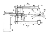
- the sole Figure of the drawing shows an X-ray examination apparatus, comprising a column 4 which is arranged on a base 2, a control panel 8 and a rotary supporting shaft 10 being arranged on an upper part 6 of said column.
- a free end 12 of the supporting shaft 10 supports a parallelogram-shaped holder 14 with a first transverse arm 16, a second transverse arm 18, a first side arm 20 and a second side arm 22.
- the transverse arms 16 and 18 are rotatable about rotary shafts 40 and 41.
- An X-ray source 24 and an X-ray detector 26 are accommodated at free ends of the side arms 20 and 22.
- a radiation vector 25 which emanates from the X-ray source 24, preferably an X-ray tube, irradiates an object 30 arranged on a supporting table 28 and is incident on the X-ray detector 26, for example an X-ray image intensifier tube or an X-ray film cassette.
- an angulation can be imparted to the radiation vector 25 by rotation of the transverse arms 16 and 18, which angulation covers a range as denoted by the radiation vector directions 251 and 252.
- the radiation vector 25 customarily extends through an isocentre 32 which is situated substantially centrally within the object to be examined, and the extreme directions 251 and 252 enclose an angle of, for example 120 o .
- a tension spring 38 is arranged between points of attachment 34 and 36 in the apparatus shown.
- a connecting line between the points of attachment 34 and 36 intersects the rotary shaft 40.
- the active force to be delivered by the spring can be optimized over the adjusting range.
- the resilient element can be accommodated in a parallelogram arm which is usually constructed as a pipe.
- the counterforce of the drive mechanism is delivered mainly by compression or in any case deformation of leads 44 and 46 for the X-ray source 24 and the X-ray detector 2, respectively, in the present embodiment.
- These leads are preferably mounted so that they closely adjoin the drive mechanism in order to prevent disturbing loops.
- the leads can be mounted so as to comprise even smaller loops for motion and can be arranged, if desired, in hollow spaces of the system of arms of the drive mechanism.
- an adjustment can be realized so that the external force to be applied is substantially constant throughout an adjusting range.
- the constant force can still be substantially lower than the maximum force otherwise required in the extreme zones of the adjusting range.
- auxiliary force in accordance with the invention can also be used for other adjustments where an increasing counterforce is experienced, for example the rotation of a C-arm and the like.
Landscapes
- Health & Medical Sciences (AREA)
- Life Sciences & Earth Sciences (AREA)
- Medical Informatics (AREA)
- Engineering & Computer Science (AREA)
- Radiology & Medical Imaging (AREA)
- Biomedical Technology (AREA)
- Biophysics (AREA)
- Nuclear Medicine, Radiotherapy & Molecular Imaging (AREA)
- Optics & Photonics (AREA)
- Pathology (AREA)
- Physics & Mathematics (AREA)
- High Energy & Nuclear Physics (AREA)
- Heart & Thoracic Surgery (AREA)
- Molecular Biology (AREA)
- Surgery (AREA)
- Animal Behavior & Ethology (AREA)
- General Health & Medical Sciences (AREA)
- Public Health (AREA)
- Veterinary Medicine (AREA)
- Apparatus For Radiation Diagnosis (AREA)
Applications Claiming Priority (2)
| Application Number | Priority Date | Filing Date | Title |
|---|---|---|---|
| NL8900028A NL8900028A (nl) | 1989-01-06 | 1989-01-06 | Roentgen onderzoek apparaat met hulpinstelkracht. |
| NL8900028 | 1989-01-06 |
Publications (2)
| Publication Number | Publication Date |
|---|---|
| EP0377247A1 true EP0377247A1 (fr) | 1990-07-11 |
| EP0377247B1 EP0377247B1 (fr) | 1994-11-02 |
Family
ID=19853913
Family Applications (1)
| Application Number | Title | Priority Date | Filing Date |
|---|---|---|---|
| EP89203285A Expired - Lifetime EP0377247B1 (fr) | 1989-01-06 | 1989-12-21 | Appareil d'examen radiologique à force de réglage auxiliaire |
Country Status (5)
| Country | Link |
|---|---|
| US (1) | US4964150A (fr) |
| EP (1) | EP0377247B1 (fr) |
| JP (1) | JPH02224743A (fr) |
| DE (1) | DE68919202T2 (fr) |
| NL (1) | NL8900028A (fr) |
Cited By (2)
| Publication number | Priority date | Publication date | Assignee | Title |
|---|---|---|---|---|
| EP0988829A1 (fr) * | 1998-09-21 | 2000-03-29 | Oec Medical Systems, Inc. | Ensemble d'équilibrage pour un bras support, utilisant un ressort à gaz |
| RU2325117C2 (ru) * | 2006-07-13 | 2008-05-27 | Федеральное государственное образовательное учреждение высшего профессионального образования Санкт-Петербургский государственный университет (СПбГУ) | Топометрическая система с функцией томографии |
Families Citing this family (5)
| Publication number | Priority date | Publication date | Assignee | Title |
|---|---|---|---|---|
| US8229196B2 (en) * | 2003-08-18 | 2012-07-24 | Rigaku Corporation | Method of detecting specific polymer crystal |
| JP4458513B2 (ja) * | 2003-08-18 | 2010-04-28 | 株式会社リガク | 特定高分子結晶の評価装置 |
| JP4113063B2 (ja) * | 2003-08-18 | 2008-07-02 | 株式会社リガク | 特定高分子結晶の検出方法 |
| WO2010108146A2 (fr) | 2009-03-20 | 2010-09-23 | Orthoscan Incorporated | Appareil mobile d'imagerie |
| US9125611B2 (en) | 2010-12-13 | 2015-09-08 | Orthoscan, Inc. | Mobile fluoroscopic imaging system |
Citations (5)
| Publication number | Priority date | Publication date | Assignee | Title |
|---|---|---|---|---|
| US3770955A (en) * | 1970-09-17 | 1973-11-06 | Hitachi Roentgen | Tomographic apparatus |
| US3892967A (en) * | 1973-12-10 | 1975-07-01 | Measurex Corp | Apparatus for radiological examination of a subject through a solid angle |
| DE2659444B1 (de) * | 1976-12-29 | 1978-01-05 | Siemens Ag | Tragarmkonstruktion mit Federgewichtsausgleich |
| DE3416823A1 (de) * | 1983-06-06 | 1984-12-06 | Friedhelm 8000 München Kreuzer | Stativ mit einem zur hoehenverstellung schenkbaren ausleger |
| EP0129361A2 (fr) * | 1983-06-16 | 1984-12-27 | Orion-Yhtymä Oy | Bras de support orientable dans différentes positions |
-
1989
- 1989-01-06 NL NL8900028A patent/NL8900028A/nl not_active Application Discontinuation
- 1989-12-21 DE DE68919202T patent/DE68919202T2/de not_active Expired - Fee Related
- 1989-12-21 EP EP89203285A patent/EP0377247B1/fr not_active Expired - Lifetime
- 1989-12-29 JP JP1344982A patent/JPH02224743A/ja active Pending
- 1989-12-29 US US07/459,049 patent/US4964150A/en not_active Expired - Fee Related
Patent Citations (5)
| Publication number | Priority date | Publication date | Assignee | Title |
|---|---|---|---|---|
| US3770955A (en) * | 1970-09-17 | 1973-11-06 | Hitachi Roentgen | Tomographic apparatus |
| US3892967A (en) * | 1973-12-10 | 1975-07-01 | Measurex Corp | Apparatus for radiological examination of a subject through a solid angle |
| DE2659444B1 (de) * | 1976-12-29 | 1978-01-05 | Siemens Ag | Tragarmkonstruktion mit Federgewichtsausgleich |
| DE3416823A1 (de) * | 1983-06-06 | 1984-12-06 | Friedhelm 8000 München Kreuzer | Stativ mit einem zur hoehenverstellung schenkbaren ausleger |
| EP0129361A2 (fr) * | 1983-06-16 | 1984-12-27 | Orion-Yhtymä Oy | Bras de support orientable dans différentes positions |
Cited By (2)
| Publication number | Priority date | Publication date | Assignee | Title |
|---|---|---|---|---|
| EP0988829A1 (fr) * | 1998-09-21 | 2000-03-29 | Oec Medical Systems, Inc. | Ensemble d'équilibrage pour un bras support, utilisant un ressort à gaz |
| RU2325117C2 (ru) * | 2006-07-13 | 2008-05-27 | Федеральное государственное образовательное учреждение высшего профессионального образования Санкт-Петербургский государственный университет (СПбГУ) | Топометрическая система с функцией томографии |
Also Published As
| Publication number | Publication date |
|---|---|
| US4964150A (en) | 1990-10-16 |
| JPH02224743A (ja) | 1990-09-06 |
| DE68919202D1 (de) | 1994-12-08 |
| EP0377247B1 (fr) | 1994-11-02 |
| DE68919202T2 (de) | 1995-05-18 |
| NL8900028A (nl) | 1990-08-01 |
Similar Documents
| Publication | Publication Date | Title |
|---|---|---|
| EP0203647B1 (fr) | Commande de direction pour un appareil de thérapie radiographique | |
| EP2271263B1 (fr) | Système de positionnement de source et/ou de détecteur | |
| EP1485024B1 (fr) | Appareil de radiographie equipe d'un detecteur de rayons x a position reglable | |
| US5436958A (en) | Adjustable collimator | |
| EP0377247B1 (fr) | Appareil d'examen radiologique à force de réglage auxiliaire | |
| US6155713A (en) | X-ray diagnostic apparatus having an X-ray generating portion and an X-ray detecting portion independent of each other | |
| US5173803A (en) | Pivoting device for supporting frames for optical observation equipment | |
| US10816132B2 (en) | Counterbalancing mechanism and stabilizer design and method for counterbalancing and stabilizing a load | |
| CA1292813C (fr) | Support asymetrique de radiographie | |
| US4649560A (en) | Digital X-ray stand | |
| US3829701A (en) | Radiation collimator | |
| US20050111626A1 (en) | Collimator, X-ray irradiator, and X-ray apparatus | |
| US4318538A (en) | Counterbalanced support | |
| KR20000023316A (ko) | 형광영상을 위한 가스스프링 역균형 l자형아암조립체 | |
| JPH08266556A (ja) | 回転角によって決まる回転モーメントを平衡させるための補正装置及びそのような補正装置を有する医療用スタンド | |
| US6789942B2 (en) | C-arm x-ray apparatus with mechanically adjustable brake | |
| EP1037557B1 (fr) | Systeme d'imagerie medicale avec mechanisme de mouvement | |
| US7158292B2 (en) | Apparatus for retaining an optical viewing device | |
| US6132087A (en) | Medical apparatus having a carrying device for at least one component | |
| US6733177B2 (en) | Friction ring for improved orbital balance of C-arm x-ray apparatus | |
| US4885761A (en) | Gravity actuated X-ray scanner | |
| US5170420A (en) | Radiological apparatus for mammographic examinations | |
| JP3746136B2 (ja) | X線診断装置 | |
| US5388141A (en) | X-ray apparatus comprising an apparatus section which is pivotable about a horizontal pivotal axis | |
| US4176278A (en) | Panoramic dental radiography employing intraoral radiation source and image intensifying means |
Legal Events
| Date | Code | Title | Description |
|---|---|---|---|
| PUAI | Public reference made under article 153(3) epc to a published international application that has entered the european phase |
Free format text: ORIGINAL CODE: 0009012 |
|
| AK | Designated contracting states |
Kind code of ref document: A1 Designated state(s): DE FR GB IT |
|
| 17P | Request for examination filed |
Effective date: 19901219 |
|
| 17Q | First examination report despatched |
Effective date: 19930317 |
|
| GRAA | (expected) grant |
Free format text: ORIGINAL CODE: 0009210 |
|
| AK | Designated contracting states |
Kind code of ref document: B1 Designated state(s): DE FR GB IT |
|
| REF | Corresponds to: |
Ref document number: 68919202 Country of ref document: DE Date of ref document: 19941208 |
|
| ITF | It: translation for a ep patent filed | ||
| ET | Fr: translation filed | ||
| ITPR | It: changes in ownership of a european patent |
Owner name: CAMBIO RAGIONE SOCIALE;PHILIPS ELECTRONICS N.V. |
|
| REG | Reference to a national code |
Ref country code: FR Ref legal event code: CD |
|
| PLBE | No opposition filed within time limit |
Free format text: ORIGINAL CODE: 0009261 |
|
| STAA | Information on the status of an ep patent application or granted ep patent |
Free format text: STATUS: NO OPPOSITION FILED WITHIN TIME LIMIT |
|
| 26N | No opposition filed | ||
| PGFP | Annual fee paid to national office [announced via postgrant information from national office to epo] |
Ref country code: GB Payment date: 19951130 Year of fee payment: 7 |
|
| PGFP | Annual fee paid to national office [announced via postgrant information from national office to epo] |
Ref country code: FR Payment date: 19951220 Year of fee payment: 7 |
|
| PGFP | Annual fee paid to national office [announced via postgrant information from national office to epo] |
Ref country code: DE Payment date: 19960223 Year of fee payment: 7 |
|
| PG25 | Lapsed in a contracting state [announced via postgrant information from national office to epo] |
Ref country code: GB Effective date: 19961221 |
|
| GBPC | Gb: european patent ceased through non-payment of renewal fee |
Effective date: 19961221 |
|
| PG25 | Lapsed in a contracting state [announced via postgrant information from national office to epo] |
Ref country code: FR Effective date: 19970829 |
|
| PG25 | Lapsed in a contracting state [announced via postgrant information from national office to epo] |
Ref country code: DE Effective date: 19970902 |
|
| REG | Reference to a national code |
Ref country code: FR Ref legal event code: ST |
|
| PG25 | Lapsed in a contracting state [announced via postgrant information from national office to epo] |
Ref country code: IT Free format text: LAPSE BECAUSE OF NON-PAYMENT OF DUE FEES;WARNING: LAPSES OF ITALIAN PATENTS WITH EFFECTIVE DATE BEFORE 2007 MAY HAVE OCCURRED AT ANY TIME BEFORE 2007. THE CORRECT EFFECTIVE DATE MAY BE DIFFERENT FROM THE ONE RECORDED. Effective date: 20051221 |