EP0377472A2 - Véhicule en miniature avec une augmentation de la traction par moyen magnétique - Google Patents
Véhicule en miniature avec une augmentation de la traction par moyen magnétique Download PDFInfo
- Publication number
- EP0377472A2 EP0377472A2 EP90100235A EP90100235A EP0377472A2 EP 0377472 A2 EP0377472 A2 EP 0377472A2 EP 90100235 A EP90100235 A EP 90100235A EP 90100235 A EP90100235 A EP 90100235A EP 0377472 A2 EP0377472 A2 EP 0377472A2
- Authority
- EP
- European Patent Office
- Prior art keywords
- vehicle
- magnets
- armature
- track
- chassis
- Prior art date
- Legal status (The legal status is an assumption and is not a legal conclusion. Google has not performed a legal analysis and makes no representation as to the accuracy of the status listed.)
- Withdrawn
Links
- 230000004907 flux Effects 0.000 claims abstract description 40
- 239000000463 material Substances 0.000 claims description 11
- 239000004020 conductor Substances 0.000 claims description 7
- 230000008878 coupling Effects 0.000 claims description 5
- 238000010168 coupling process Methods 0.000 claims description 5
- 238000005859 coupling reaction Methods 0.000 claims description 5
- 238000004804 winding Methods 0.000 claims description 4
- 239000000696 magnetic material Substances 0.000 claims description 3
- 230000008093 supporting effect Effects 0.000 claims description 3
- 230000009977 dual effect Effects 0.000 abstract 1
- 239000000725 suspension Substances 0.000 description 7
- 230000000717 retained effect Effects 0.000 description 5
- 230000001133 acceleration Effects 0.000 description 4
- 230000000712 assembly Effects 0.000 description 3
- 238000000429 assembly Methods 0.000 description 3
- 230000007246 mechanism Effects 0.000 description 3
- 230000004048 modification Effects 0.000 description 3
- 238000012986 modification Methods 0.000 description 3
- 229910001369 Brass Inorganic materials 0.000 description 2
- CWYNVVGOOAEACU-UHFFFAOYSA-N Fe2+ Chemical compound [Fe+2] CWYNVVGOOAEACU-UHFFFAOYSA-N 0.000 description 2
- XEEYBQQBJWHFJM-UHFFFAOYSA-N Iron Chemical compound [Fe] XEEYBQQBJWHFJM-UHFFFAOYSA-N 0.000 description 2
- 230000009471 action Effects 0.000 description 2
- 239000010951 brass Substances 0.000 description 2
- 238000010276 construction Methods 0.000 description 2
- 239000002184 metal Substances 0.000 description 2
- 229910052751 metal Inorganic materials 0.000 description 2
- 241000270281 Coluber constrictor Species 0.000 description 1
- JJLJMEJHUUYSSY-UHFFFAOYSA-L Copper hydroxide Chemical compound [OH-].[OH-].[Cu+2] JJLJMEJHUUYSSY-UHFFFAOYSA-L 0.000 description 1
- 229910000831 Steel Inorganic materials 0.000 description 1
- 238000007792 addition Methods 0.000 description 1
- 239000000853 adhesive Substances 0.000 description 1
- 230000001070 adhesive effect Effects 0.000 description 1
- 230000000694 effects Effects 0.000 description 1
- OQZCSNDVOWYALR-UHFFFAOYSA-N flurochloridone Chemical compound FC(F)(F)C1=CC=CC(N2C(C(Cl)C(CCl)C2)=O)=C1 OQZCSNDVOWYALR-UHFFFAOYSA-N 0.000 description 1
- 239000003292 glue Substances 0.000 description 1
- 238000005286 illumination Methods 0.000 description 1
- 229910052742 iron Inorganic materials 0.000 description 1
- 238000003475 lamination Methods 0.000 description 1
- 230000009834 selective interaction Effects 0.000 description 1
- 239000010959 steel Substances 0.000 description 1
- 238000006467 substitution reaction Methods 0.000 description 1
Images


Classifications
-
- A—HUMAN NECESSITIES
- A63—SPORTS; GAMES; AMUSEMENTS
- A63H—TOYS, e.g. TOPS, DOLLS, HOOPS OR BUILDING BLOCKS
- A63H18/00—Highways or trackways for toys; Propulsion by special interaction between vehicle and track
- A63H18/12—Electric current supply to toy vehicles through the track
-
- A—HUMAN NECESSITIES
- A63—SPORTS; GAMES; AMUSEMENTS
- A63H—TOYS, e.g. TOPS, DOLLS, HOOPS OR BUILDING BLOCKS
- A63H18/00—Highways or trackways for toys; Propulsion by special interaction between vehicle and track
- A63H18/16—Control of vehicle drives by interaction between vehicle and track; Control of track elements by vehicles
- A63H2018/165—Means to improve adhesion of the vehicles on the track, e.g. using magnetic forces
Definitions
- This invention relates, generally, to miniature electrical vehicles which ride on a track that includes electric power rails and, more particularly, to an improved electric motor arrangement for such a vehicle with an advantageous magnet structure which provides magnetic attraction between the vehicle and the power rails so as to increase the traction of the vehicle against the track.
- the prior art includes a plurality of electrically powered miniature vehicles usually in the form of automobile race cars, which ride on a track.
- the track is usually fabricated of a type of plastic and includes at least a pair of power rails embedded in the track.
- the power rails are electrically conductive, typically of metal such as brass or the like, and are used to provide electrical power to the vehicle.
- Miniature vehicles of this general type have been successfully manufactured and marketed in the past. These vehicles include magnets which form the stator of the electrical motor. The electrical power is supplied to the rotor or armature of the motor via a commutator which receives electrical power from the rails via contacts or "shoes" mounted on the vehicle. The armature is typically positioned horizontally between the North/South poles of the magnets.
- the weight of the car prevents further improvements. That is, as weight is reduced, traction is reduced. On the other hand, as weight is increased, acceleration and speed are reduced.
- This patent is directed to an electric motor arrangement, in a miniature vehicle, which provides increased traction without increasing the weight of the vehicle.
- the permanent magnets of the motor extend downwardly from the vehicle in close proximity to the power rails and exert an attractive force between the rails and the magnets. The attractive force increases the normal force on the car on the track and improves the traction thereof.
- U.S. Patent No. 4,031,661 - MINIATURE VEHICLE WITH MAGNETIC ENHANCEMENT OF TRACTION - R. Bernhard This patent is directed to an electrically operated miniature vehicle for use on a track which has magnetic material embedded in it. More specifically, this device includes a miniature vehicle with a pair of magnets oriented in compartments at opposite sides of the vehicle on either side of the armature. A flux collector associated with each magnet is disposed between the magnet and a side wall of the vehicle and includes a pair of tabs at the upper end which engages the top of a side wall of the vehicle and a flange at its bottom which extends under the magnet. This flange supports the magnet within the vehicle and in close proximity to the power rails, and also enchances the magnetic force applied to the rails.
- This invention relates to an electrically powered toy vehicle of the type frequently referred to as a slot car racer.
- the arrangment of the vehicle is, for the most part, conventional.
- the magnets are mounted so that the North-South axis is disposed in the vertical direction thus yielding greater down force on the rails of the conventional track. More particularly, the N/S axis of the magnets is substantially normal to the track surface. This arrangement permits the magnets to be used within the motor and to provide an optimum magnetic down force over a broader face of the magnet.
- the guide pin which is used to maintain the car on the track is modified to provide a "live axle". That is, the wheels are mounted to the opposite ends of a common axle which is retained in the vehicle by a modified guide pin. This arrangement permits the wheels to be independently and interdependently positioned on the track.
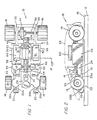
- a miniature, electrically-powered vehicle designated generally by the reference numeral 10.
- the vehicle 10 is constructed to ride over the surface of a continuous track 12 (See Figure 2) on its front wheels 14 and its rear or driving wheels 16.
- Electric power for the vehicle is provided by a pair of continous, parallel, electrical rails 18 (see Figure 2) which are embedded in track 12.
- the rails 18 may, if desired, protrude above track 12.
- the rails 18 are made of a material which is attracted by a "magnetic" material, typically, but not limited to, steel.
- a pair of pick-up shoes 20 extend downwardly from the bottom of the vehicle 10.
- Track 12 also includes a continuous slot 15 therein (see Figure 4) which is parallel to and between rails 18.
- the slot 15 is intended to receive a guide pin 22 which extends downwardly from the front of the vehicle 10.
- the vehicle 10 includes a supporting chassis 24 and a body 26, of any desired configuration, which is fitted to the chassis.
- Chassis 24 is, typically, made of a sturdy plastic material which is lightweight and non-magnetic.
- the chassis 24 includes a floor 28 and a number of vertical walls or wall components to which the other elements of the vehicle are mounted.
- each of front wheels 14 is rotatably mounted on a separate and independent axle 30 which extends outwardly from the floor 28 at the front of the vehicle 10.
- Guide pin 22 is also mounted at the front of the vehicle between front wheels 14 by conventional means, e.g. a force fit in a slot in the front end of floor 28.
- Guide pin 22 also extends downwardly below chassis 24 and into the slot 15 in track 12.
- a crown gear 11 is coaxially secured to axle 32 between the wheels 16.
- Axle 32 is journaled in parallel side walls 35 of vehicle 10 in suitable fashion.
- An electric motor is mounted in the chassis 24 and receives electric power from the power rails 18 through shoes 20 and drives wheels 16 to propel the miniature vehicle 10 around the track 12.
- the electric motor includes an armature assembly 36 which forms the rotor of the electric motor and is coaxially mounted on drive shaft 38 which is oriented along the length of the vehicle 10.
- Drive shaft 38 terminates in a coaxially secured pinion 64 which meshes with crown gear 11 to transfer power to rear wheels 16.
- Drive shaft 38 is a journaled in a pair of bearings 40 and 41 which are mounted, respectively, in walls 42 and 44 of chassis 24.
- the bearings 40 and 41 are made of brass to present low friction to the rotation of shaft 38.
- each of bearings 40 and 41 includes a pair of rectangular flanges at its ends which restrain the bearing against axial movement.
- the bearings 40 and 41 are retained in vertical guideways or slots cut in walls 42 and 44, respectively.
- the guideways are slightly narrower than the outside diameter of the respective bearing, but include a detent at the end of the guideways so that the bearings may be pressed down into the guideways and be retained in position therein.
- the armature assembly 36 includes a generally cylindrical core 46 which is, typically, comprised of a plurality of disk-like soft iron laminations (as seen best in fig. 3). As best seen in Figure 4, the core 46 is partly cut away or slotted to form three core segments 46a. A separate winding 47 of insulated wire is wound on each of the core segments 46a in the conventional fashion for miniature electric motors.
- a segmented commutator 48 is coaxially mounted on shaft 38 between bearing 41 and armature 36. The commutator 48 serves as an electrical contact for supplying electrical power to the windings 47. Thus, electrical power is provided from rails 18 to commutator 48 by means of contact shoes 20 and a pair of brush assemblies 49 which include brushes 50.
- the brush assemblies 49 are mounted on floor 28 on either side of commutator 48 and the brush assemblies 49 are retained by means of spring clips 53.
- Spring clips 53 each have a first end 53a retained by a lug 55 protruding upwardly from chassis floor 28.
- a second end 53b of each clip 53 extends down through a hole 28a in floor 28 and is detachably coupled to a first end 20a of one of shoes 20.
- Each of shoes 20 extends towards the front of the vehicle and curves upward over a projection 28b of floor 28 as seen in Figures 1 and 2.
- each shoe 20 is bifurcated and curves downward and over projection 28b so that the bifurcation straddles the projection.
- a spring 51 disposed between the bottom of floor 28 and the top surface of contact shoe 20 keeps the shoe biased for continuous engagement with rail 18 whereby vehicle 10 is continually provided with electric power.
- the stationary or stator component of the electric motor comprises a pair of magnets 52 each mounted in a compartment of chassis 24 on either side of armature 36.
- the compartments are substantially open at the bottom and at the side adjacent to the armature. This permits the magnets to extend through the floor of chassis 24 and to be in close proximity to rails 18 thereby providing an attractive force holding vehicle 10 to track 12.
- Each of magnet compartments is formed by a portion of wall 42, a side wall 56 opposite the armature, a wall 58, and projections which extend normal to walls 42 and 58, respectively. This construction of the vehicle is substantially conventional
- the magnets 52 are identical in configuration and assembly. (As best seen in Figures 1 and 3, each of the magnets 52 conforms to the shape of the compartment 54 in chassis 24.) That is, both magnets 52 have the South pole on the bottom and the North pole at the top or (vice versa). That is, both magnets have the South/North axis vertically aligned (rather than horizontally as in the prior art). While the magnets are generally rectilinear, each magnet 52 may have the inner surface thereof curved to conform to armature 36 in a preferred embodiment.
- Flux bridge 60 preferably made of ferrous sheet material, is mounted to interconnect the magnets 52.
- flux bridge 60 has the ends thereof joined to the upper surface (for example the North pole) of each of the magnets 52.
- the center portion of the flux bridge is curved so that it overpasses the motor, in particular the armature portion, of the vehicle.
- the flux bridge 60 can be made flat without the curved portion, per se.
- the flux bridge 60 has the effect of joining the magnets 52 to provide a more complete flux path for the motor.
- pole pieces 52a extend outwardly from the bottom of the magnets 52 toward the motor. It has been found that pole pieces 52a can provide a considerable increase in the magnetic flux applied to the motor 10 by the magnets 52.
- the particular configuration for the pole pieces 52a shown in Figures 4 is adequate to provide magnetic flux to the motor and, as well provide the broad magnetic flux surface from magnets 52 to the rail 18 and, yet, permit utilization of a smaller magnet. That is, because the the flux bridge 60 covers and contacts most (if not all) of the top surfaces of magnets 52 and is made of a ferrous material, it represents a relatively low reluctance path for magnetic flux or field lines. Thus, those magnetic flux lines which normally emanate from the top or back of magnet 52 and disperse into the space surrounding the vehicle 10 are concentrated in flux bridge 60 and are directed downwardly, in parallel, so as to emanate from the bottom of magnets 52.
- the bottom surfaces (for example, South poles) of magnets 52 are generally disposed above the rails 18, whereby the concentrated field lines which emanate from each magnet 52 are directed to the respective rail 18. This arrangement results in a stronger magnetic attraction than is provided by the horizontally mounted magnets of the prior art even when used with flux collector devices.
- the side mounted magnets 52 have the North/South axis arranged vertically. However, in this embodiment a much lower profile magnet is used. This can be the result of the use of materials with improved magnetic properties, for example. All other known models employ a motor design wherein the North/South axis orientation of the magnets is horizontal thus limiting the magnetic down force available over the rails.
- pole pieces 154 can be provided at the lower surfaces of the magnets 52. These pole pieces, which function akin to the flux collectors of the prior art, are used primarily to redirect the magnetic flux lines from the magnets 152 toward the armature 36. However, the advantages described above relative to the instant invention are realized, as well.
- FIG. 5 there is shown a schematic representation (partially in section) of the front end suspension of miniature electrical vehicles which are known in the art.
- the front wheels 514 are the type which are conventional in the art.
- the wheels 514 are fixed to the chassis 528 of the vehicle by means of suitable mounting means 529.
- the separate and independent axle 530 for each wheel 514 is mounted in the mounting 529.
- a guide pin 550 is also mounted in the chassis 528.
- the chassis 528 includes a groove or snap-in portion in the front thereof. This groove receives the center core 523 of the guide pin 550 which is disposed between the two horizontal plates 524 and 525 of the guide pin 550.
- the dimensions of the snap-in groove and the guide pin components are arranged so that a tight fit is effected so that the depending guide pin 522 can be used to guide the vehicle around the track by depending into slot 515 in the track 12.
- the guide pin mechanism can be adhered to the chassis by means of glue or other suitable adhesive.
- the wheels 514 are mounted to fixed axles and a rigid suspension system is provided. This system permits the vehicles to "jump" off the track with any bumps or warped portions of the track.
- FIG. 6 there shown a new and improved guide pin 600 which is useful for providing another embodiment of the instant invention.
- the new guide pin permits a "live axle” apparatus as described hereinafter.
- the guide pin 600 includes the plates 624 and 625 as well as the guide-plate 661.
- the barrel or core 623 is disposed between the plates 624 and 625.
- the guide pin 600 is similar to the prior art device. However, in the guide pin 600 an additional barrel 659 is provided between the plates 624 and 651.
- the barrels 623 and 659 are of substantially the same diameter. However, in a preferred embodiment, the barrel 659 is taller than the barrel 623.
- the depending guide pin 622 extends below the lower plate of the guide pin as in the case of the prior art.
- the guide pin 600 below plate 624 i.e. from the plate 624 to the bottom of depending guide pin 622 is substantially identical to the guide pin 522 shown in Figure 5.
- the barrel 623 will mate with the groove or slot in the base of the racing car apparatus which is identical to that of the prior art. However, the barrel 659 and plate 661 extend above the chassis 528 of the vehicle, as described hereinafter.
- improved guide pin 600 is mounted into the chassis 528 in the same fashion as in the prior art. However, as noted, the barrel 659 extends above the chassis.
- the vehicle axle 700 referred to as a "live axle" is disposed in vertical slots 701 which are formed in vertical walls 702 on opposite sides of the chassis 528.
- the slots 701 are closed at the bottom but open at the top. These slots have a vertical length substantially equal to the height of the side wall 702. When the axle 700 is placed within these slots, the axle is free to move, vertically, at either end thereof.
- axle 700 is disposed under the plate 661 of guide pin 600 and behind the barrel 659 of pin 600.
- the slots 701 are disposed in the wall 702 in an arrangement relative to the guide pin 600 so that the axle 700 is maintained within the slots 701 and below plate 661.
- the axle 700 is free to move vertically between the plates 651 and 624.
- axle 700 is free to move vertically at either end.
- the relationship between barrel 659, plates 623 and 661 and the vertical length of slots 701 is such that the axle does not become disengaged from side wall 702.
- the "live axle” 700 is permitted to freely move at either end (or both ends if need be). This will permit the vehicle to operate on a track which has become warped, for example.
- the rear wheels of the vehicle are generally not arranged to have such a live axle in order to maintain full contact with the track.
- FIG. 9 there is shown a schematic representation of the arrangement of the guide pin 600 relative to the chassis 528, as well as the side walls 702. Since the bottom portion of pin 600 is mounted substantially perpendicular to chassis 528 and included in the slot or groove in the front thereof, the axle 700 is retained by plate 661 of pin 600 but is free to move, vertically, within slot 701. This arrangement permits a free, live action suspension.
Landscapes
- Toys (AREA)
- Dc Machiner (AREA)
Applications Claiming Priority (2)
| Application Number | Priority Date | Filing Date | Title |
|---|---|---|---|
| US293622 | 1989-01-05 | ||
| US07/293,622 US4940444A (en) | 1989-01-05 | 1989-01-05 | Miniature vehicle with magnetic enhancement of traction |
Publications (2)
| Publication Number | Publication Date |
|---|---|
| EP0377472A2 true EP0377472A2 (fr) | 1990-07-11 |
| EP0377472A3 EP0377472A3 (fr) | 1991-07-17 |
Family
ID=23129836
Family Applications (1)
| Application Number | Title | Priority Date | Filing Date |
|---|---|---|---|
| EP19900100235 Withdrawn EP0377472A3 (fr) | 1989-01-05 | 1990-01-05 | Véhicule en miniature avec une augmentation de la traction par moyen magnétique |
Country Status (3)
| Country | Link |
|---|---|
| US (1) | US4940444A (fr) |
| EP (1) | EP0377472A3 (fr) |
| JP (1) | JPH02264689A (fr) |
Cited By (5)
| Publication number | Priority date | Publication date | Assignee | Title |
|---|---|---|---|---|
| EP0553555A3 (en) * | 1991-12-30 | 1993-10-20 | Refined Ind Co Ltd | Improvements in toy cars |
| ES2119673A1 (es) * | 1996-01-25 | 1998-10-01 | Garzon De La Calle Eduardo | Mejoras introducidas en coches electricos miniatura desplazables sobre pistas con ranuras de guiado. |
| RU2264838C1 (ru) * | 2004-05-26 | 2005-11-27 | Савиновский Виталий Георгиевич | Аттракцион савиновского в.г. |
| WO2005063349A3 (fr) * | 2003-12-23 | 2006-01-26 | Valerio Accerenzi | Vehicule electrique jouet avec poignee amelioree |
| CN100342937C (zh) * | 2002-05-30 | 2007-10-17 | 麦特尔公司 | 玩具车磁耦合装置和含有该磁耦合装置的玩具车 |
Families Citing this family (27)
| Publication number | Priority date | Publication date | Assignee | Title |
|---|---|---|---|---|
| US5268534A (en) * | 1992-03-27 | 1993-12-07 | Gailey Brian L | Braided flattened tube conductor |
| US5342048A (en) * | 1993-02-05 | 1994-08-30 | California R & D Center | Wall mounted slot car track with moving accessories |
| US5752880A (en) * | 1995-11-20 | 1998-05-19 | Creator Ltd. | Interactive doll |
| US5678489A (en) * | 1996-07-08 | 1997-10-21 | Studio Eluceo Ltd. | Electrically-operated moving body travelling on a rail capable of explaining free quadrants described in the mobius theorem |
| DE10003557C2 (de) * | 2000-01-27 | 2001-12-06 | Sts Racing Gmbh | Spielfahrzeug mit verstellbarer Magnethaftung |
| RU2206361C1 (ru) * | 2001-10-18 | 2003-06-20 | Савиновский Виталий Георгиевич | Аттракцион савиновского в.г. |
| RU2210422C1 (ru) * | 2001-11-30 | 2003-08-20 | Савиновский Виталий Георгиевич | Аттракцион савиновского в.г. |
| DE10243150B3 (de) * | 2002-07-25 | 2004-05-06 | Stadlbauer Spiel- Und Freizeitartikel Gmbh | Fahrspielzeug f+r spurgeführte Autorennbahnen |
| US6891101B2 (en) * | 2002-09-30 | 2005-05-10 | George Riach, Jr. | Non-invasive magnetic arrangement for a vehicle and method of use |
| US7770524B1 (en) * | 2002-10-08 | 2010-08-10 | Battat Incorporated | Drive and secure mechanism for toy vehicle and track |
| RU2261748C1 (ru) * | 2003-12-26 | 2005-10-10 | Савиновский Виталий Георгиевич | Аттракцион волшебная трасса савиновского в.г. |
| RU2262973C1 (ru) * | 2004-02-17 | 2005-10-27 | Савиновский Виталий Георгиевич | Автомобиль для аттракциона в.г. савиновского |
| RU2283158C2 (ru) * | 2004-11-09 | 2006-09-10 | Виталий Георгиевич Савиновский | Аттракцион савиновского в.г. (варианты) |
| CN1788821B (zh) * | 2004-12-16 | 2010-08-11 | 马特尔有限公司 | 玩具车 |
| RU2284843C1 (ru) * | 2005-02-07 | 2006-10-10 | Виталий Георгиевич Савиновский | Аттракцион савиновского в.г. (варианты) |
| CA2525022C (fr) * | 2005-06-16 | 2010-07-13 | Jonathan Bedford | Trousse de jeu a ensemble de piste pour vehicule et chariot |
| US7517272B2 (en) * | 2005-06-16 | 2009-04-14 | Jonathan Bedford | Play set with toy vehicle track and carriage |
| WO2007032693A1 (fr) * | 2005-09-16 | 2007-03-22 | Maglevvision Corporation | Véhicule-jouet à lévitation magnétique et son procédé de propulsion |
| WO2007122601A1 (fr) * | 2006-04-23 | 2007-11-01 | Michael Taft | Véhicule d'escalade doté d'une roue adhésive |
| US7946903B2 (en) * | 2006-05-04 | 2011-05-24 | Mattel, Inc. | Wheeled toy vehicles and playsets for use therewith |
| KR101006849B1 (ko) * | 2008-12-31 | 2011-01-12 | 한국철도기술연구원 | 바퀴식 초고속 철도 시스템 |
| US8777689B1 (en) * | 2010-02-13 | 2014-07-15 | Phillip H. Neal | Environmentally-responsive transforming vehicles |
| DE102010008014A1 (de) * | 2010-02-15 | 2011-08-18 | Siemens Aktiengesellschaft, 80333 | Führungssystem für medizinische Anlagen, medizinische Anlage, fahrbare Transportvorrichtung sowie Verfahren |
| US9314705B2 (en) | 2010-08-27 | 2016-04-19 | Mattel, Inc. | Toy track set |
| US20130040533A1 (en) * | 2011-08-12 | 2013-02-14 | Andrew Kevin Miller | Miniature vehicle and set |
| HK1184013A2 (en) * | 2013-06-17 | 2014-01-10 | 雅田国际有限公司 | Toy slot car with protective cover for conductive elements |
| TWM559739U (zh) * | 2017-05-16 | 2018-05-11 | Wang Wen Po | 立體高速軌道車玩具 |
Family Cites Families (15)
| Publication number | Priority date | Publication date | Assignee | Title |
|---|---|---|---|---|
| DE1074463B (de) * | 1960-01-28 | VEB Elektroinstallation Oberlmd Sonneberg (Thur) | Modell Lokomo ive mit Dauermagnet Motor | |
| US3350953A (en) * | 1965-12-20 | 1967-11-07 | Edward R Stewart | Brake-drive assembly for miniature racing cars |
| US3596397A (en) * | 1970-02-13 | 1971-08-03 | Anthony Colletti | Miniature slot car |
| US3690393A (en) * | 1971-03-19 | 1972-09-12 | Donna Kramer | Magnetic wheel |
| US3813812A (en) * | 1973-01-31 | 1974-06-04 | Marvin Glass & Associates | System for operating miniature vehicles |
| US3964206A (en) * | 1975-02-03 | 1976-06-22 | Aurora Products Corporation | Miniature vehicle with magnetic force |
| US4031661A (en) * | 1976-01-19 | 1977-06-28 | Aurora Products Corporation | Miniature vehicle with magnetic enhancement of traction |
| US4429488A (en) * | 1981-10-13 | 1984-02-07 | Wessels John A | Electric vehicle with magnetic attraction to trackway |
| US4386777A (en) * | 1982-03-22 | 1983-06-07 | Aurora Products Canada Limited | Toy vehicle racing game |
| US4479650A (en) * | 1982-04-26 | 1984-10-30 | Hermann Neuhierl | Toy-racing express motor road |
| DE3240712C2 (de) * | 1982-11-04 | 1984-11-08 | Hermann Dipl.-Chem. Dr. 8510 Fürth Neuhierl | Spielfahrzeug mit Magnethaftung für eine Autorennbahn |
| DE3327667C1 (de) * | 1982-11-04 | 1985-02-14 | Hermann Dipl.-Chem. Dr. 8510 Fürth Neuhierl | Elektromotorisch angetriebenes Spielfahrzeug mit Magnethaftung für eine Autorennbahn |
| EP0110386B1 (fr) * | 1982-11-29 | 1988-05-18 | Georg Utz AG | Véhicule-jouet guidé et pouvant rouler sur un tracé conducteur ferromagnétique |
| US4568300A (en) * | 1985-01-15 | 1986-02-04 | Marvin Glass & Associates | Toy team racing set |
| EP0200837A3 (en) * | 1985-05-09 | 1987-01-07 | Sankei Kk | Vehicle |
-
1989
- 1989-01-05 US US07/293,622 patent/US4940444A/en not_active Expired - Fee Related
-
1990
- 1990-01-05 EP EP19900100235 patent/EP0377472A3/fr not_active Withdrawn
- 1990-01-05 JP JP2000910A patent/JPH02264689A/ja active Pending
Cited By (5)
| Publication number | Priority date | Publication date | Assignee | Title |
|---|---|---|---|---|
| EP0553555A3 (en) * | 1991-12-30 | 1993-10-20 | Refined Ind Co Ltd | Improvements in toy cars |
| ES2119673A1 (es) * | 1996-01-25 | 1998-10-01 | Garzon De La Calle Eduardo | Mejoras introducidas en coches electricos miniatura desplazables sobre pistas con ranuras de guiado. |
| CN100342937C (zh) * | 2002-05-30 | 2007-10-17 | 麦特尔公司 | 玩具车磁耦合装置和含有该磁耦合装置的玩具车 |
| WO2005063349A3 (fr) * | 2003-12-23 | 2006-01-26 | Valerio Accerenzi | Vehicule electrique jouet avec poignee amelioree |
| RU2264838C1 (ru) * | 2004-05-26 | 2005-11-27 | Савиновский Виталий Георгиевич | Аттракцион савиновского в.г. |
Also Published As
| Publication number | Publication date |
|---|---|
| JPH02264689A (ja) | 1990-10-29 |
| EP0377472A3 (fr) | 1991-07-17 |
| US4940444A (en) | 1990-07-10 |
Similar Documents
| Publication | Publication Date | Title |
|---|---|---|
| US4940444A (en) | Miniature vehicle with magnetic enhancement of traction | |
| US4386777A (en) | Toy vehicle racing game | |
| US4990117A (en) | Magnetic force-guided travelling toy | |
| US4648610A (en) | Light emitting roller skate wheels | |
| JP2525828B2 (ja) | レ―シング玩具の走行軌道変更装置 | |
| US4031661A (en) | Miniature vehicle with magnetic enhancement of traction | |
| US3159109A (en) | Toy | |
| JPH0433915Y2 (fr) | ||
| US4031660A (en) | Illuminated action toy | |
| US4854909A (en) | Apparatus for transferring a running track of a racing toy | |
| US3964206A (en) | Miniature vehicle with magnetic force | |
| JP2002166064A (ja) | 走行玩具用サスペンション及び走行玩具 | |
| JP2002512500A (ja) | 改良電動機 | |
| US4571204A (en) | Stunt toy device | |
| JP2003230771A (ja) | 走行玩具 | |
| WO2007097899A2 (fr) | Système de déplacement électromagnétique | |
| EP0633045B1 (fr) | Appareillage pour jeu de course | |
| CN201186616Y (zh) | 沿着单轨导轨运行的玩具车 | |
| CA2007345A1 (fr) | Vehicule miniature a traction magnetique amelioree | |
| JPH0639756Y2 (ja) | リニアモーター式軌道走行玩具 | |
| US4570092A (en) | Driving apparatus useful in a movable toy | |
| EP0553555A2 (fr) | Voiture-jouet | |
| EP0105058B1 (fr) | Appareil de mise en marche utilisable dans un jouet mobile | |
| CN219440662U (zh) | 一种儿童磁悬浮列车玩具 | |
| JPH09313744A (ja) | 車両走行玩具 |
Legal Events
| Date | Code | Title | Description |
|---|---|---|---|
| PUAI | Public reference made under article 153(3) epc to a published international application that has entered the european phase |
Free format text: ORIGINAL CODE: 0009012 |
|
| AK | Designated contracting states |
Kind code of ref document: A2 Designated state(s): AT BE CH DE DK ES FR GB IT LI LU NL SE |
|
| PUAL | Search report despatched |
Free format text: ORIGINAL CODE: 0009013 |
|
| AK | Designated contracting states |
Kind code of ref document: A3 Designated state(s): AT BE CH DE DK ES FR GB IT LI LU NL SE |
|
| STAA | Information on the status of an ep patent application or granted ep patent |
Free format text: STATUS: THE APPLICATION IS DEEMED TO BE WITHDRAWN |
|
| 18D | Application deemed to be withdrawn |
Effective date: 19920118 |