EP0377703B1 - Ferrure pour meubles comprenant une pluralite de tiroirs superposes - Google Patents
Ferrure pour meubles comprenant une pluralite de tiroirs superposes Download PDFInfo
- Publication number
- EP0377703B1 EP0377703B1 EP89906705A EP89906705A EP0377703B1 EP 0377703 B1 EP0377703 B1 EP 0377703B1 EP 89906705 A EP89906705 A EP 89906705A EP 89906705 A EP89906705 A EP 89906705A EP 0377703 B1 EP0377703 B1 EP 0377703B1
- Authority
- EP
- European Patent Office
- Prior art keywords
- drawer
- rotary thrust
- angular
- thrust member
- projection
- Prior art date
- Legal status (The legal status is an assumption and is not a legal conclusion. Google has not performed a legal analysis and makes no representation as to the accuracy of the status listed.)
- Expired - Lifetime
Links
Images


Classifications
-
- E—FIXED CONSTRUCTIONS
- E05—LOCKS; KEYS; WINDOW OR DOOR FITTINGS; SAFES
- E05B—LOCKS; ACCESSORIES THEREFOR; HANDCUFFS
- E05B65/00—Locks or fastenings for special use
- E05B65/46—Locks or fastenings for special use for drawers
- E05B65/462—Locks or fastenings for special use for drawers for two or more drawers
- E05B65/463—Drawer interlock or anti-tilt mechanisms, i.e. when one drawer is open, at least one of the remaining drawers is locked
Definitions
- the present invention relates to a fitting according to the preamble of claim 1.
- the switch cam is designed as a pin attached to an arm, the arm being fastened to a rail part which can be extended with the drawer.
- This pin works together with a rotary valve designed as a lever, which can be pivoted into two end positions by means of a tension spring.
- the fork lever is pivoted so that after a relatively short distance the pin attached to the arm comes out of engagement with the fork lever. Since the rotary valve was moved past the dead center, it remains in this position.
- the pin of the arm engages the fork lever. As soon as the dead center has been overcome, the drawer is pulled into the end position by the spring and also held in this position.
- This fitting is designed so that all drawers, for example a storage cabinet or a desk, can be brought into the extended position. For safety reasons, however, only one drawer should be extendable if possible. On the other hand, it is also desired that the drawers remain in the closed position so that the front panel rests against the front of the piece of furniture without any gaps.
- Another disadvantage is the fact that the drawer cannot be moved back into the closed position if the rotary slide valve is inadvertently manually pivoted into the position corresponding to the closed position of the drawer when the drawer is extended.
- the present invention relates to a fitting according to the preamble of claim 1.
- the switch cam is designed as a pin attached to the drawer, which interacts with a rotary slide designed as a fork lever, which in two by means of a tension spring End positions is pivotable.
- the fork lever is pivoted so that after a relatively short distance the pin disengages from the fork lever. Since the rotary valve has been moved past the dead center, it remains in this position.
- the pin engages the fork lever. As soon as the dead center has been overcome, the drawer is pulled into the end position by the spring and also held in this position.
- This fitting is designed so that all drawers, for example a storage cabinet or a desk, can be brought into the extended position. For safety reasons, however, only one drawer should be extendable if possible. On the other hand, it is also desired that the drawers remain in the closed position so that the front panel rests against the front of the piece of furniture without any gaps.
- Another disadvantage is the fact that the drawer cannot be moved back into the closed position if the rotary slide valve is inadvertently manually pivoted into the position corresponding to the closed position of the drawer when the drawer is extended.
- the present invention has for its object to develop a fitting of the type mentioned so that only one of several drawers can be extended, each drawer being pulled into the closed position and held in this position when retracting over a relatively short distance, and that in spite of incorrect operation, each drawer can be brought into the closed position, whereby the inserted drawer should be prevented from springing back if it is retracted at too high a speed or too much force.
- the rotary valve now not only has the task of bringing the drawer to be retracted into the closed position over the last relatively short section to be held, but also to prevent the remaining drawers from being extended when the drawer is extended in cooperation with the blocking rail.
- the rotary valve can therefore be seen in the sense of a drive element for the blocking rail.
- the double function results in a particularly simple construction.
- the fitting in question is referred to in the industry as a self-closing fitting.
- Springback is not only achieved by the spring-loaded rotary valve, but also by the interaction of the rotary rail with the blocking rail, which in turn creates a brake link.
- subclaim 2 it is achieved by the features of subclaim 2 that when the drawer extends, the switching cam moved in synchronism firstly strikes the free edge of the spring bar, thereby moving the entire rotary slide and simultaneously rotating it over a partial distance so that the switching cam disengages from the Rotary valve is coming.
- the rotary valve normally remains in this position.
- retracting the switch cam runs on the stop cam of the rotary valve, whereby the rotary valve is moved back to the starting position against the previous movement while simultaneously rotating in opposite directions.
- the rotary valve remains in its angular position when the drawer is extended, so that there is no need to overcome a dead center, for which purpose the spring force would first have to be increased in an unfavorable manner.
- claim 4 ensure that only a single part is necessary for the guidance of the blocking rail and for the movable mounting of the rotary valve. This simplifies assembly. In addition, only one tool is required if this molded body is designed as a plastic injection molded part. In addition, furniture can subsequently be retrofitted with the fitting in a particularly simple manner, since the molded body can be screwed onto the furniture body. The furniture body itself does not need any additional guides for the blocking rail.
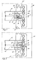
- the fitting shown in the figures is screwed to the inner surface of a side wall 10 of a piece of furniture at the smallest possible distance from the front. Fitting is necessary for each drawer 11 indicated in FIG. 5. It is sufficient for the function if the fitting is provided on one side. 5 that it lies above the drawer 11. This arrangement is advisable since the height of the front panel of a drawer is usually greater than the height of the actual drawer.
- the fitting has a rotary slide 12, which has a hanging pin 13 for a tension spring 14 on the side facing away from the furniture body.
- the other end of the tension spring 14 is suspended from a pin of a shaped body 15, which will be explained in more detail.
- the tension spring 14 is under tension.
- the switching cam 16 is formed on a block 17, which is fixed by means of a fastening bracket 18 to an angled leg of the side wall of the drawer 11.
- a driving pin 19 is attached to the rotary slide valve 12 on the side facing the side wall 10 of the furniture body, the central longitudinal axis of which is aligned with the central longitudinal axis of the hanging pin 13 for the tension spring 14. These central longitudinal axes form the axis of rotation of the rotary slide 12.
- the driving pin 19 penetrates a horizontal guide groove 20 provided in the molded body 15.
- the length of the driving pin 19 is so large that the free end face passes through the guide groove 20 and engages in an angular groove 21 of a blocking rail 22.
- Fig. 6 shows that the locking rail 22 is guided in a guide channel 23.
- the length of the guide groove 20 and the width of the blocking rail 22 are essentially the same.
- the guide groove 20 opens into the guide channel 23.
- the blocking rail has at least as many angular grooves 21 as the furniture contains drawers 11. 3 and 4, however, several angular grooves are provided in order to be able to use the same blocking rails 22 for drawers of different heights. In the partial sections, only the upper and lower angular grooves 21 are used, as will be explained.
- the rotary slide valve 12 On the side facing away from the side wall 10, the rotary slide valve 12 has a stop cam 25 which is offset from its axis of rotation and a spring bar 26 which is at an acute angle to the plane of movement of the rotary slide valve 12.
- the spring bar 26 In the closed position of the drawer 11 shown in Fig. 1, the spring bar 26 is at the same height as the stop cam 25.
- the distance between the mutually facing surfaces of the stop cam 25 and the spring bar 26 is so large that the switching cam 16 in the thereby limited space can intervene.
- the drawer 10 is removed from the furniture moved out, the switching cam 16 moves in synchronism in the direction of arrow E.
- the rotary valve is moved in a synchronous linear movement with simultaneous rotation according to the representations according to FIGS. 1 and 2 counterclockwise.
- Fig. 3 the position of the driving pin 19 of two superposed drawers 11 is shown in the closed position. Due to the linear movement of the rotary valve 12 by the extension of the upper drawer 11, the driving pin 19 lifts the blocking rail 22.
- the angular grooves 21 consist of a vertically extending section and an inclined part standing thereon. The vertical section is close to the long side facing away from the front of the furniture. The sloping section extends essentially over the entire width of the blocking rail 22. If all the drawers 11 are in the closed position, all the driving pins 19 of the rotary slide 12 lie at the apex of the two sections.
- the rotary valve 12 has a guide plate 27, on which the stop cam 25 and the spring bar 26 are molded.
- the guide plate 27 is guided in two vertically superimposed slots of the molded body 15.
- the guide plate 27 In the basic contour, the guide plate 27 is circular so that rotation is possible. However, so that it is better guided in the slots, it has two guide surfaces at right angles to one another on the side facing the front of the furniture.
- a further detent and guide bracket 28 is formed on the guide plate 27 and has a sliding surface that is parallel to the lower guide surface of the guide plate 27. This will make the rotary valve 12 guided perfectly during the linear movement.
- the outer webs delimiting the slots for the guide plate 27 are designed in the form of a circular arc in the area facing the front of the piece of furniture, the center coinciding with the central longitudinal axis of the driving pin 19 of the rotary slide 12, based on the position of the rotary slide 12 shown in FIG. 2 with the drawer 11 pulled out.
- the arcs interact with the stop cams 25 and the detent and guide bracket 28 so that the rotary slide 12 remains in the position shown in FIG. 2 until the switch cam 16 abuts the outer surface of the stop cam 25 .
- the molded body 15 is T-shaped. 5 and 6 that it is composed of two parts 29, 30 with essentially the same basic contour. This makes assembly easier.
- Each part 29, 30 has a groove 31, 32, which in the assembled state form the guide channel 23 for the blocking rail 22.
- the parts are connected to each other on the side facing away from the front of the furniture via a film hinge 33, so that after the insertion of the rotary slide 12 and the tension spring 14, the parts 29, 30 can be folded together for screwing onto the side wall 10. Due to the hinge-like design, a part 29 or 30 can never be lost.
- the angular grooves 21 are formed as openings in the illustrated embodiment.
Landscapes
- Drawers Of Furniture (AREA)
- Undergarments, Swaddling Clothes, Handkerchiefs Or Underwear Materials (AREA)
- Stackable Containers (AREA)
- Medicines That Contain Protein Lipid Enzymes And Other Medicines (AREA)
- Treating Waste Gases (AREA)
- Pharmaceuticals Containing Other Organic And Inorganic Compounds (AREA)
Claims (10)
- Ferrure destinée à un meuble comportant plusieurs tiroirs superposés, pourvue d'une coulisse rotative (12) à ressort équipant chaque tiroir (11), pouvant être déplacée par une came de commutation (16) suivant le mouvement du tiroir (11) et décalée en hauteur par rapport à l'axe de rotation de la coulisse rotative (12), caractérisée en ce qu'entre une paroi latérale (10) du corps du meuble et la paroi latérale du tiroir (11) est prévu un rail de guidage (22) déplaçable dans le sens vertical et s'étendant sensiblement sur toute la hauteur de tous les tiroirs (11), présentant des rainures angulaires (21) en nombre correspondant au nombre des tiroirs (11), constituées chacune d'une partie oblique et d'une partie verticale, en ce qu'un doigt d'entraînement (19) formé sur la coulisse rotative (12) correspondante s'engage dans chaque rainure angulaire (21), en ce que la coulisse rotative (12) est rotative autour de l'axe longitudinal médian du doigt d'entraînement (19), et est coulissante dans la direction de déplacement du tiroir (11) correspondant, de telle sorte qu'en position de fermeture de tous les tiroirs (11), les doigts d'entraînement (19) de toutes les coulisses rotatives (12) se trouvent au point culminant des rainures angulaires (21), afin que, lorsqu'un tiroir (11) est ouvert, le rail de blocage (22) soit amené à se déplacer dans le sens vertical, par le doigt d'entraînement (19) de la coulisse rotative (12) se déplaçant à l'intérieur de la partie oblique de la rainure angulaire (21), ce qui a pour effet que les doigts d'entraînement (19) des coulisses rotatives (12) restantes s'engagent dans les parties verticales des rainures angulaires (21) et bloquent les tiroirs (11).
- Ferrure selon la revendication 1, caractérisée en ce que chaque coulisse rotative (12) présente, sur le côté orienté vers la paroi latérale du tiroir (11), une came de butée (25) et une barrette à ressort (26) oblique et espacée par rapport à cette dernière, la barrette à ressort (26) étant disposée en regard de la face frontale du tiroir (11), et en ce qu'à l'état fermé du tiroir (11), la came de commutation (16) se trouve dans l'interstice limité par la came de butée (25) et la barrette à ressort.
- Ferrure selon la revendication 2, caractérisée en ce que la came de butée (25) est constituée par une came d'enclenchement bloquant la coulisse rotative (12) lorsque le tiroir (11) est ouvert.
- Ferrure selon la revendication 1, caractérisée en ce que chaque coulisse rotative (12) est disposée dans un corps profilé (15) pouvant être fixé sur le corps du meuble, et en ce que ce corps profilé (15) présente un canal de guidage (23) pour le rail de blocage (22).
- Ferrure selon la revendication 1, caractérisée en ce que la coulisse rotative (12) possède une plaque de guidage (27) présentant au moins une surface de guidage, en ce que, sur la plaque de guidage (27) sont formés, du côté orienté vers la paroi latérale du tiroir (11), une autre équerre de guidage et d'enclenchement (28) et un tenon d'accrochage (13), en alignement avec le doigt d'entraînement (19) pour un ressort de traction (14), et en ce que la plaque de guidage (27) est guidée dans deux fentes de guidage prévues dans le corps profilé (15) et superposées verticalement.
- Ferrure selon la revendication 5, caractérisée en ce que les barrettes extérieures limitant la fente de guidage présentent, dans les zones orientées vers la face frontale du tiroir (11), des arcs de cercle, qui, en action conjuguée avec l'équerre de guidage et d'enclenchement (28) et avec la came de butée (25), bloquent la coulisse rotative (12) lorsque le tiroir (11) est ouvert.
- Ferrure selon la revendication 1, caractérisée en ce que la partie verticale de chaque rainure angulaire (21) prévue dans le rail de blocage (22) est située dans la zone de bordure opposée à la face frontale du meuble, et en ce que la partie oblique s'étend sur sensiblement toute la largeur du rail de blocage (22).
- Ferrure selon la revendication 7, caractérisée en ce que les parties formant la rainure angulaire (21) sont orientées pour former un angle d'environ 45°.
- Ferrure selon la revendication 4, caractérisée en ce que le contour de base du corps profilé (15) a une forme de T, ce corps étant formé de deux parties (29, 30) superposables, en ce que chaque partie présente une rainure (31, 32) formant le canal de guidage (23) pour le rail de blocage (22), et en ce que les parties (29, 30) sont reliées l'une à l'autre au moyen d'une charnière à film (33) sur le côté opposé au côté frontal du tiroir (11).
- Ferrure selon la revendication 1, caractérisée en ce que la came de commutation (16) est fixée sur la paroi latérale du tiroir (11) grâce à une équerre de fixation (18).
Priority Applications (2)
| Application Number | Priority Date | Filing Date | Title |
|---|---|---|---|
| EP92114955A EP0529679B1 (fr) | 1988-07-05 | 1989-06-13 | Dispositif de fermeture pour tiroir coulissant dans un meuble |
| AT89906705T ATE92574T1 (de) | 1988-07-05 | 1989-06-13 | Beschlag fuer ein mehrere uebereinander angeordnete schubkaesten aufweisendes moebel. |
Applications Claiming Priority (2)
| Application Number | Priority Date | Filing Date | Title |
|---|---|---|---|
| DE3822678 | 1988-07-05 | ||
| DE3822678A DE3822678A1 (de) | 1988-07-05 | 1988-07-05 | Beschlag fuer ein mehrere uebereinander angeordnete schubkaesten aufweisendes moebel |
Related Child Applications (1)
| Application Number | Title | Priority Date | Filing Date |
|---|---|---|---|
| EP92114955.5 Division-Into | 1992-09-02 |
Publications (2)
| Publication Number | Publication Date |
|---|---|
| EP0377703A1 EP0377703A1 (fr) | 1990-07-18 |
| EP0377703B1 true EP0377703B1 (fr) | 1993-08-04 |
Family
ID=6357970
Family Applications (2)
| Application Number | Title | Priority Date | Filing Date |
|---|---|---|---|
| EP92114955A Revoked EP0529679B1 (fr) | 1988-07-05 | 1989-06-13 | Dispositif de fermeture pour tiroir coulissant dans un meuble |
| EP89906705A Expired - Lifetime EP0377703B1 (fr) | 1988-07-05 | 1989-06-13 | Ferrure pour meubles comprenant une pluralite de tiroirs superposes |
Family Applications Before (1)
| Application Number | Title | Priority Date | Filing Date |
|---|---|---|---|
| EP92114955A Revoked EP0529679B1 (fr) | 1988-07-05 | 1989-06-13 | Dispositif de fermeture pour tiroir coulissant dans un meuble |
Country Status (12)
| Country | Link |
|---|---|
| US (1) | US5040858A (fr) |
| EP (2) | EP0529679B1 (fr) |
| JP (1) | JP2664092B2 (fr) |
| AT (1) | ATE117044T1 (fr) |
| AU (1) | AU613212B2 (fr) |
| CA (1) | CA1323652C (fr) |
| DE (3) | DE3822678A1 (fr) |
| DK (1) | DK170308B1 (fr) |
| ES (1) | ES2013949A6 (fr) |
| FI (1) | FI88533C (fr) |
| RU (1) | RU1800960C (fr) |
| WO (1) | WO1990000661A1 (fr) |
Families Citing this family (40)
| Publication number | Priority date | Publication date | Assignee | Title |
|---|---|---|---|---|
| AT401334B (de) * | 1990-07-31 | 1996-08-26 | Blum Gmbh Julius | Schliessvorrichtung für schubladen |
| US5207781A (en) * | 1989-04-03 | 1993-05-04 | Julius Blum Gesellschaft M.B.H. | Closing device for moving a drawer to a fully inserted position within a furniture body |
| DE9007365U1 (de) * | 1990-06-26 | 1991-07-11 | Karl Lautenschläger GmbH & Co KG Möbelbeschlagfabrik, 6107 Reinheim | Einzugsautomatik für Schubladen-Ausziehführungen |
| AT400219B (de) * | 1991-12-24 | 1995-11-27 | Blum Gmbh Julius | Schliessvorrichtung für schubladen |
| AT400212B (de) * | 1992-05-12 | 1995-11-27 | Svoboda Moebelwerk | Auszugsperre für schubladen |
| US5303994A (en) * | 1992-06-05 | 1994-04-19 | Steelcase Inc. | Drawer interlock |
| US6378963B1 (en) | 1996-11-04 | 2002-04-30 | Drustar, Inc. | Modular drawer system |
| JP3145655B2 (ja) * | 1997-06-12 | 2001-03-12 | 株式会社稲葉製作所 | 引出しの開閉装置 |
| US6254205B1 (en) | 1999-02-02 | 2001-07-03 | Thomas Regout Usa Inc. | Rail assembly with homing device and interlock |
| DE29918558U1 (de) * | 1999-10-21 | 1999-12-23 | Paul Hettich Gmbh & Co., 32278 Kirchlengern | Laufschiene einer Schubkastenführung mit einer Befestigungs- und Höhenjustiervorrichtung |
| US6971729B1 (en) | 2000-05-01 | 2005-12-06 | Accuride International, Inc. | Self-closing slide |
| JP4394327B2 (ja) | 2000-05-01 | 2010-01-06 | アキュライド インターナショナル,インコーポレイテッド | 自動閉止スライド及び自動閉止スライド用機構 |
| US20060082266A1 (en) * | 2000-05-01 | 2006-04-20 | Le Hai D | Self-moving slides and self-moving mechanisms |
| ES2214077B1 (es) * | 2001-05-08 | 2005-06-01 | Talleres Lupiñen, S.L. | Dispositivo de cerrojo de seguridad. |
| US6634726B1 (en) | 2001-05-30 | 2003-10-21 | Snap-On Technologies, Inc. | Multiple drawer cabinet allowing one drawer opened at a time |
| US6722749B1 (en) | 2001-08-14 | 2004-04-20 | Snap-On Technologies, Inc. | Drawer open position controller |
| GB2380516B (en) * | 2001-10-05 | 2005-07-27 | Accuride Int Ltd | Rear interlock |
| CA2389563A1 (fr) * | 2002-06-05 | 2003-12-05 | Rousseau Metal Inc. | Mecanisme de securite pour cabinet |
| ES2220220B1 (es) * | 2003-05-23 | 2006-02-16 | Ojmar, S.A. | Sistema de bloqueo para cajones de muebles. |
| AT413630B (de) * | 2003-07-24 | 2006-04-15 | Fulterer Gmbh | Ausziehsperreinrichtung |
| US7104691B2 (en) | 2003-07-31 | 2006-09-12 | Accuride International, Inc. | Self-moving slide, mechanism for self-moving slide and method for self-moving a slide |
| US7469979B2 (en) * | 2004-03-19 | 2008-12-30 | Steelcase Inc. | Pedestal system |
| US7641296B2 (en) | 2004-11-05 | 2010-01-05 | Accuride International, Inc. | Self-moving mechanism and slide incorporating the same |
| CN100556338C (zh) * | 2004-11-05 | 2009-11-04 | 艾库里德国际有限公司 | 阻尼移动机构及包括该机构的滑动装置 |
| US8016374B2 (en) * | 2005-11-10 | 2011-09-13 | Grass Gmbh | Pull-out slide for drawers and drawer |
| US7481503B2 (en) | 2006-01-19 | 2009-01-27 | Steelcase Inc. | Storage cabinet assembly |
| US7441848B2 (en) * | 2006-01-23 | 2008-10-28 | King Slide Works Co., Ltd. | Automatic homing mechanism for a multi-sectional slide |
| TWI321996B (en) | 2007-02-17 | 2010-03-21 | King Slide Works Co Ltd | Slide assembly having an automatic retractable device |
| US8147010B2 (en) * | 2007-08-09 | 2012-04-03 | King Slide Works Co., Ltd. | Slide assembly having an automatic retractable device |
| DE202007015212U1 (de) * | 2007-11-02 | 2008-01-24 | Anton Schneider Gmbh & Co Kg | Befestigungsvorrichtung für Möbelteile |
| US7600828B2 (en) * | 2007-12-20 | 2009-10-13 | King Slide Works Co., Ltd. | Slide assembly having a homing device |
| DE202009000050U1 (de) * | 2009-01-22 | 2010-06-17 | Paul Hettich Gmbh & Co. Kg | Schließsystem eines ausziehbaren Möbelteils und Möbel |
| DE202009013411U1 (de) | 2009-10-23 | 2011-03-10 | Paul Hettich Gmbh & Co. Kg | Schließsystem eines ausziebaren Möbelteils und Möbel |
| DE102010000326A1 (de) * | 2010-02-05 | 2011-08-11 | Paul Hettich GmbH & Co. KG, 32278 | Schließsystem für ausziehbare Möbelteile und Möbel |
| AT509331B1 (de) | 2010-05-28 | 2011-08-15 | Fulterer Gmbh | Ausziehsperrvorrichtung für mindestens zwei ausziehbare möbelteile |
| AT511116B1 (de) | 2011-03-10 | 2013-01-15 | Fulterer Gmbh | Ausziehsperrvorrichtung |
| AT512306B1 (de) | 2012-01-25 | 2013-07-15 | Fulterer Gmbh | Vorrichtung zur dämpfung der bewegung eines beweglich gelagerten bauteils |
| US9777513B2 (en) * | 2012-01-25 | 2017-10-03 | Fulterer Gesellschaft Mbh | Pull-out device for at least two pull-out furniture parts |
| DE102012109751B4 (de) * | 2012-10-12 | 2023-08-03 | Paul Hettich Gmbh & Co. Kg | Auszugführung eines ausziehbaren Möbelteils und Möbel |
| DE102021108249A1 (de) * | 2021-03-31 | 2022-10-06 | Paul Hettich Gmbh & Co. Kg | Koppelelement, Schließsystem und Möbel |
Family Cites Families (4)
| Publication number | Priority date | Publication date | Assignee | Title |
|---|---|---|---|---|
| DE2717152C3 (de) * | 1977-04-19 | 1981-12-17 | Fa. Louis Leitz, 7000 Stuttgart | Auszugsperre für ein mehrere übereinander angeordnete Schubkästen aufweisendes Möbelstück |
| DE2916245A1 (de) * | 1979-04-21 | 1980-11-06 | 3K Bueromoebel Gmbh | Auszugssperre |
| US4396239A (en) * | 1981-03-10 | 1983-08-02 | Paradyne Corporation | Interlock mechanism |
| FR2514236A1 (fr) * | 1981-10-08 | 1983-04-15 | Roneo Cie | Meuble de classement a tiroirs a dispositif d'appel en fin de course de fermeture des tiroirs |
-
1988
- 1988-07-05 DE DE3822678A patent/DE3822678A1/de not_active Withdrawn
-
1989
- 1989-06-13 EP EP92114955A patent/EP0529679B1/fr not_active Revoked
- 1989-06-13 AT AT92114955T patent/ATE117044T1/de not_active IP Right Cessation
- 1989-06-13 EP EP89906705A patent/EP0377703B1/fr not_active Expired - Lifetime
- 1989-06-13 AU AU37541/89A patent/AU613212B2/en not_active Ceased
- 1989-06-13 DE DE58908888T patent/DE58908888D1/de not_active Revoked
- 1989-06-13 WO PCT/DE1989/000386 patent/WO1990000661A1/fr not_active Ceased
- 1989-06-13 US US07/490,673 patent/US5040858A/en not_active Expired - Lifetime
- 1989-06-13 DE DE8989906705T patent/DE58905164D1/de not_active Expired - Fee Related
- 1989-06-13 JP JP1506107A patent/JP2664092B2/ja not_active Expired - Fee Related
- 1989-07-03 ES ES8902347A patent/ES2013949A6/es not_active Expired - Lifetime
- 1989-07-04 CA CA000604677A patent/CA1323652C/fr not_active Expired - Fee Related
-
1990
- 1990-02-27 DK DK050790A patent/DK170308B1/da not_active IP Right Cessation
- 1990-03-02 RU SU904743274A patent/RU1800960C/ru active
- 1990-03-02 FI FI901097A patent/FI88533C/fi not_active IP Right Cessation
Also Published As
| Publication number | Publication date |
|---|---|
| FI88533B (fi) | 1993-02-15 |
| DE3822678A1 (de) | 1990-01-11 |
| EP0529679A1 (fr) | 1993-03-03 |
| ATE117044T1 (de) | 1995-01-15 |
| JPH03500313A (ja) | 1991-01-24 |
| FI88533C (fi) | 1993-05-25 |
| CA1323652C (fr) | 1993-10-26 |
| DK170308B1 (da) | 1995-07-31 |
| DE58908888D1 (de) | 1995-02-23 |
| DK50790D0 (da) | 1990-02-27 |
| ES2013949A6 (es) | 1990-06-01 |
| AU613212B2 (en) | 1991-07-25 |
| US5040858A (en) | 1991-08-20 |
| AU3754189A (en) | 1990-02-05 |
| JP2664092B2 (ja) | 1997-10-15 |
| FI901097A0 (fi) | 1990-03-02 |
| EP0529679B1 (fr) | 1995-01-11 |
| RU1800960C (ru) | 1993-03-07 |
| DE58905164D1 (de) | 1993-09-09 |
| WO1990000661A1 (fr) | 1990-01-25 |
| DK50790A (da) | 1990-02-27 |
| EP0377703A1 (fr) | 1990-07-18 |
Similar Documents
| Publication | Publication Date | Title |
|---|---|---|
| EP0377703B1 (fr) | Ferrure pour meubles comprenant une pluralite de tiroirs superposes | |
| DE3731667C2 (fr) | ||
| DE19547049C2 (de) | Auszugsperre für übereinander angeordnete Schubladen | |
| EP0606564A1 (fr) | Dispositif de réglage de l'orientation de tiroirs et similaires | |
| EP1500763B1 (fr) | Dispositif pour empêcher l'ouverture simultanée de tiroirs | |
| EP0677634B1 (fr) | Serrure mortaisée, en particulier pour portes de maison, notamment crémone | |
| DE69718853T2 (de) | Dekorplatte mit Vorrichtung zum senkrechten Verschieben längs der geschlossenen Tür eines eingebauten Gerätes | |
| DE4325920A1 (de) | Ausziehsperre für Möbelauszüge | |
| DE2703207C3 (de) | Lüftungsvorrichtung für Räume | |
| DE3429699C2 (de) | Fehlbedienungssperre für Treibstangenbeschläge | |
| DE3335306A1 (de) | Fehlbedienungssperre fuer treibstangenbeschlaege | |
| DE9300260U1 (de) | Verstelleinrichtung zur Ausrichtung eines Schubkastens, Auszuges o.dgl. | |
| DE1759934B1 (de) | Beschlag fuer Schiebetueren | |
| DE2243916A1 (de) | Kippriegel-verschlussbeschlag fuer kipp-schwenkfluegel-fenster und -tueren od. dgl | |
| DE202004001998U1 (de) | Ausziehsperreinrichtung | |
| CH446949A (de) | Treibstangenverschluss | |
| DE3135609A1 (de) | "buerotisch" | |
| DE19534648A1 (de) | Feststellvorrichtung für einen Schwenkflügel | |
| DE1179692B (de) | Abdichtungsvorrichtung fuer Tueren | |
| DE9320014U1 (de) | Verschluß zur zentralen Ver- und Entriegelung | |
| EP0578844B1 (fr) | Table avec plateau de table réglable | |
| DE1559925C3 (de) | Eck-Umschaltgetriebe für die Flügel von Dreh-Kippfenstern od. dgl | |
| DE20012281U1 (de) | Verschluß zur zentralen Ver- und Entriegelung von Auszügen | |
| DE29622589U1 (de) | Zentralverriegelung mit Auszugssperre für Schubladenschränke | |
| EP0672811A1 (fr) | Verrouillage de fausse manoeuvre pour une tringle de commande d'une fenêtre, d'une porte ou similaire |
Legal Events
| Date | Code | Title | Description |
|---|---|---|---|
| PUAI | Public reference made under article 153(3) epc to a published international application that has entered the european phase |
Free format text: ORIGINAL CODE: 0009012 |
|
| 17P | Request for examination filed |
Effective date: 19891229 |
|
| AK | Designated contracting states |
Kind code of ref document: A1 Designated state(s): AT BE CH DE FR GB IT LI NL SE |
|
| 17Q | First examination report despatched |
Effective date: 19920227 |
|
| ITF | It: translation for a ep patent filed | ||
| GRAA | (expected) grant |
Free format text: ORIGINAL CODE: 0009210 |
|
| AK | Designated contracting states |
Kind code of ref document: B1 Designated state(s): AT BE CH DE FR GB IT LI NL SE |
|
| REF | Corresponds to: |
Ref document number: 92574 Country of ref document: AT Date of ref document: 19930815 Kind code of ref document: T |
|
| GBT | Gb: translation of ep patent filed (gb section 77(6)(a)/1977) |
Effective date: 19930810 |
|
| REF | Corresponds to: |
Ref document number: 58905164 Country of ref document: DE Date of ref document: 19930909 |
|
| ET | Fr: translation filed | ||
| PLBE | No opposition filed within time limit |
Free format text: ORIGINAL CODE: 0009261 |
|
| STAA | Information on the status of an ep patent application or granted ep patent |
Free format text: STATUS: NO OPPOSITION FILED WITHIN TIME LIMIT |
|
| 26N | No opposition filed | ||
| EAL | Se: european patent in force in sweden |
Ref document number: 89906705.2 |
|
| REG | Reference to a national code |
Ref country code: GB Ref legal event code: IF02 |
|
| PGFP | Annual fee paid to national office [announced via postgrant information from national office to epo] |
Ref country code: FR Payment date: 20020617 Year of fee payment: 14 |
|
| PGFP | Annual fee paid to national office [announced via postgrant information from national office to epo] |
Ref country code: BE Payment date: 20020620 Year of fee payment: 14 |
|
| PGFP | Annual fee paid to national office [announced via postgrant information from national office to epo] |
Ref country code: CH Payment date: 20020621 Year of fee payment: 14 |
|
| PGFP | Annual fee paid to national office [announced via postgrant information from national office to epo] |
Ref country code: SE Payment date: 20020624 Year of fee payment: 14 |
|
| PG25 | Lapsed in a contracting state [announced via postgrant information from national office to epo] |
Ref country code: SE Free format text: LAPSE BECAUSE OF NON-PAYMENT OF DUE FEES Effective date: 20030614 |
|
| PG25 | Lapsed in a contracting state [announced via postgrant information from national office to epo] |
Ref country code: LI Free format text: LAPSE BECAUSE OF NON-PAYMENT OF DUE FEES Effective date: 20030630 Ref country code: CH Free format text: LAPSE BECAUSE OF NON-PAYMENT OF DUE FEES Effective date: 20030630 Ref country code: BE Free format text: LAPSE BECAUSE OF NON-PAYMENT OF DUE FEES Effective date: 20030630 |
|
| BERE | Be: lapsed |
Owner name: PAUL *HETTICH G.M.B.H. & CO. Effective date: 20030630 |
|
| EUG | Se: european patent has lapsed | ||
| REG | Reference to a national code |
Ref country code: CH Ref legal event code: PL |
|
| PG25 | Lapsed in a contracting state [announced via postgrant information from national office to epo] |
Ref country code: FR Free format text: LAPSE BECAUSE OF NON-PAYMENT OF DUE FEES Effective date: 20040227 |
|
| REG | Reference to a national code |
Ref country code: FR Ref legal event code: ST |
|
| PG25 | Lapsed in a contracting state [announced via postgrant information from national office to epo] |
Ref country code: IT Free format text: LAPSE BECAUSE OF NON-PAYMENT OF DUE FEES Effective date: 20050613 |
|
| PGFP | Annual fee paid to national office [announced via postgrant information from national office to epo] |
Ref country code: NL Payment date: 20060619 Year of fee payment: 18 |
|
| PGFP | Annual fee paid to national office [announced via postgrant information from national office to epo] |
Ref country code: GB Payment date: 20060626 Year of fee payment: 18 |
|
| PGFP | Annual fee paid to national office [announced via postgrant information from national office to epo] |
Ref country code: AT Payment date: 20070622 Year of fee payment: 19 |
|
| PGFP | Annual fee paid to national office [announced via postgrant information from national office to epo] |
Ref country code: DE Payment date: 20070801 Year of fee payment: 19 |
|
| GBPC | Gb: european patent ceased through non-payment of renewal fee |
Effective date: 20070613 |
|
| NLV4 | Nl: lapsed or anulled due to non-payment of the annual fee |
Effective date: 20080101 |
|
| PG25 | Lapsed in a contracting state [announced via postgrant information from national office to epo] |
Ref country code: NL Free format text: LAPSE BECAUSE OF NON-PAYMENT OF DUE FEES Effective date: 20080101 |
|
| PG25 | Lapsed in a contracting state [announced via postgrant information from national office to epo] |
Ref country code: GB Free format text: LAPSE BECAUSE OF NON-PAYMENT OF DUE FEES Effective date: 20070613 |
|
| PG25 | Lapsed in a contracting state [announced via postgrant information from national office to epo] |
Ref country code: DE Free format text: LAPSE BECAUSE OF NON-PAYMENT OF DUE FEES Effective date: 20090101 Ref country code: AT Free format text: LAPSE BECAUSE OF NON-PAYMENT OF DUE FEES Effective date: 20080613 |