EP1500763B1 - Dispositif pour empêcher l'ouverture simultanée de tiroirs - Google Patents
Dispositif pour empêcher l'ouverture simultanée de tiroirs Download PDFInfo
- Publication number
- EP1500763B1 EP1500763B1 EP04016496A EP04016496A EP1500763B1 EP 1500763 B1 EP1500763 B1 EP 1500763B1 EP 04016496 A EP04016496 A EP 04016496A EP 04016496 A EP04016496 A EP 04016496A EP 1500763 B1 EP1500763 B1 EP 1500763B1
- Authority
- EP
- European Patent Office
- Prior art keywords
- locking device
- drawer
- connecting rod
- arrangement according
- interlock arrangement
- Prior art date
- Legal status (The legal status is an assumption and is not a legal conclusion. Google has not performed a legal analysis and makes no representation as to the accuracy of the status listed.)
- Expired - Lifetime
Links
- 238000006073 displacement reaction Methods 0.000 claims description 22
- 238000013016 damping Methods 0.000 claims description 17
- 230000000903 blocking effect Effects 0.000 claims description 16
- 238000000034 method Methods 0.000 claims description 14
- 230000008569 process Effects 0.000 claims description 8
- 230000000694 effects Effects 0.000 claims description 3
- 230000008878 coupling Effects 0.000 claims 1
- 238000010168 coupling process Methods 0.000 claims 1
- 238000005859 coupling reaction Methods 0.000 claims 1
- 238000003780 insertion Methods 0.000 claims 1
- 230000037431 insertion Effects 0.000 claims 1
- 241001295925 Gegenes Species 0.000 description 3
- 230000003750 conditioning effect Effects 0.000 description 3
- 238000010276 construction Methods 0.000 description 2
- 238000009434 installation Methods 0.000 description 2
- 239000000969 carrier Substances 0.000 description 1
- 210000003746 feather Anatomy 0.000 description 1
- 230000005294 ferromagnetic effect Effects 0.000 description 1
- 230000003993 interaction Effects 0.000 description 1
- 230000007257 malfunction Effects 0.000 description 1
- 238000012986 modification Methods 0.000 description 1
- 230000004048 modification Effects 0.000 description 1
Images




Classifications
-
- E—FIXED CONSTRUCTIONS
- E05—LOCKS; KEYS; WINDOW OR DOOR FITTINGS; SAFES
- E05B—LOCKS; ACCESSORIES THEREFOR; HANDCUFFS
- E05B65/00—Locks or fastenings for special use
- E05B65/46—Locks or fastenings for special use for drawers
- E05B65/462—Locks or fastenings for special use for drawers for two or more drawers
- E05B65/463—Drawer interlock or anti-tilt mechanisms, i.e. when one drawer is open, at least one of the remaining drawers is locked
- E05B65/464—Drawer interlock or anti-tilt mechanisms, i.e. when one drawer is open, at least one of the remaining drawers is locked comprising two or more lock elements aligned in end-to-end abutting relation
-
- E—FIXED CONSTRUCTIONS
- E05—LOCKS; KEYS; WINDOW OR DOOR FITTINGS; SAFES
- E05B—LOCKS; ACCESSORIES THEREFOR; HANDCUFFS
- E05B17/00—Accessories in connection with locks
- E05B17/0041—Damping means
Definitions
- a closing push rod is provided which can be raised only by a predetermined displacement, which is traversed when pivoting one of the locking devices, whereupon this uppermost push rod abuts against a stop. A pivoting of one or more other locking devices is thereby blocked. These other locking devices thus lock the extension of another drawer.
- Such Ausziehsperr adopted example, from the EP 1 154 107 A2 known.
- the locking devices are pivotable about vertical axes which coincide with the longitudinal axes of the push rods.
- the locking devices in this case have at least one inclined surface, whereby a projecting in the axial direction of the push rods cam is formed.
- the push rods have a cooperating with the inclined surface of the push rod inclined surface, so that when pivoting the locking device between its base position and its active position an increase in the above the locking device arranged push rod.
- the locking devices are in turn mounted displaceably in height, wherein the locking devices lying above the extended drawer are also raised when extending this lower drawer. Above the uppermost locking device, a stop is provided which limits the displacement of the uppermost locking device upward, so that not several of the locking devices can be pivoted simultaneously into their active position.
- the catch attached to the drawer pivots back the rotary valve and the rotary valve is moved from a tension spring to its starting position withdrawn.
- the locking device performing rotary slide is guided simultaneously displaceable, locked in the active position as a whole and locked in its pivoted position against a provision in its base position, wherein he simultaneously lifts the blocking rail in its displacement in the active position.
- the object of the invention is to provide a Ausziehsperr adopted of the type mentioned, which has a relation to conventional Ausziehsperr respondeden this type improved functionality, with a reliable construction is achieved, which has a long life and is characterized by good operability. According to the invention, this is achieved by a pull-out locking device having the features of patent claim 1.
- a Ausziehsperr rose invention a direct-inducsfunktion for the drawers is integrated, which causes an automatic collection of the respective drawer over the last part of the Einfahrrange the drawer. This prevents a drawer from being retracted completely, which would also prevent it from being pulled out of another drawer.
- a Ausziehsperr contemporary invention further comprises a damping unit, which dampens a method of the carriage from its second end position (in the active position of the locking device) in its first end position (in the base position of the locking device).
- substantially no damping takes place in the other direction of the method of the carriage.
- a pneumatic piston-cylinder unit is preferably provided, the piston is damped in the retraction direction and in the extension direction substantially unattenuated against the cylinder is movable.
- Such damped in a direction of displacement pneumatic piston-cylinder units are known, inter alia in the Connection with damped self-closing devices.
- such piston-cylinder units in the AT 005 527 U1 .
- a respective locking device is in its base position laterally outside the displacement path of the push rod or push rods, with which it cooperates, and is in its active position in the displacement of the push rod or push rods.
- Such Ausziehsperr interests can be easily formed, since in the adjustment of the locking device in its active position by means of the driver no increase of other locking devices takes place, so that the raised weight can be kept low.
- Such Ausziehsperr interests can be used flexibly and in terms of height, via which a locking device cooperates with the drawer, compact form, wherein the locking member is advantageously pivotable relative to the carriage about a vertical pivot axis.
- the inventive design of the locking device which has a relative to the carriage pivotable locking part, this can fulfill their combined functions in an advantageous manner, with a good guidance of the carriage and a reliable blocking of the present in its second end position slide against a process in its first end position is possible.
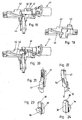
- An Ausziehsperr worn invention has a locking device 1 ( Fig. 16 ) for each drawer 2 engaged by the pull-out locking device.
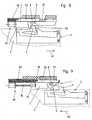
- the locking device 1 comprises a carriage 7 which, in a bearing unit 9 assigned to a respective locking device 1, extends in the extension and retraction direction 60, 61 (FIG. Fig. 8, 9 ) is mounted linearly displaceable, and a locking member 5, which is pivotable relative to the carriage 7 about a pivot axis 8.
- the locking device 1 acts with a on the cooperating with this locking device 1 drawer 2 driver 3 ( Fig. 17 ), which is mounted in the illustrated embodiment on the underside of the drawer 2 and has a lying below the plane of the bottom of the drawer 2 driving pin 4.
- the interaction of the locking device 1 with the driver 3 is to be understood so that on the one hand the locking device 1 from the driver 3 when extending one of the drawers is actuated, on the other hand, the locking device 1 locks the associated drawer against being pulled out when one of the other drawers is extended, by holding the catch 3 attached to the drawer 2, as will become more apparent from the following description.
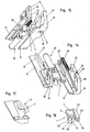
- the bearing units 9 are formed in two parts in the embodiment shown and comprise a bottom part 10 with a bottom plate 11 and a cover part 12 with a cover plate 13, as shown in these FIGS. 14 and 15 is apparent.
- a cover plate 13 is a recessed guide track 14 for a thickened portion of the carriage 7 of the locking device, said thickened portion of the carriage 7, as will be explained in more detail below, an actuating part 23 for cooperation with the associated push rods 24 to 26 forms.
- the bottom part 10 and the cover part 12 are connected to each other, for example with engaging in openings 20 of the bottom part 10 pin of the cover part 12th
- the cooperating with the locking devices 1 push rods 24, 25, 26 have attached to the ends of rod-shaped Mitteil kind end pieces 27, 28, in the bearing units 9 in the axial direction of the push rods, which are preferably vertical, are mounted linearly displaceable.
- the bottom part 10 and the cover part 12 have recesses which together form a continuous vertical guide track 29.
- this guideway 29 has vertically extending webs 30, 31 projecting on both sides, which engage in vertical grooves 57, 58 in the side surfaces of the end pieces 27, 28.
- the displacement of each projecting from above into the guide rail 29 tail 27 is limited by a stop which is formed in the embodiment shown by a projection 32 which abuts the edge of a corresponding recess 54 in the end piece 27.
- the lower and upper end pieces 27, 28 of the push rods 24, 25, 26 cooperate with the actuating parts 23 of the locking devices 1.
- These actuating members 23 are formed by the guided in the guideways 14 thickened portions of the carriage 7 of the locking devices 1.
- the end pieces 27, 28 facing ends of the actuating members 23 are wedge-shaped and have upwardly and downwardly directed inclined surfaces 33, 34 which cooperate with downwardly and upwardly inclined surfaces 35, 36 on the end pieces 27, 28 ,
- this locking device 1 upwardly projecting push rod 24 by conditioning the inclined surface 33 of the actuating member 23 on the inclined surface 35 of the end piece 27 from its lowered position in which it bears against the stop formed by the projection 32, in accordance with its raised position Fig. 5 raised, wherein in the active position of the locking device 1, the top of the actuating member 23 is located below an end face 37 of the end piece 27. In the raised position of the push rod 24 is the upper end piece 28 with an end portion in the displacement of the next higher drawer 2 associated locking device 1. An extension of this locking device 1 from its basic position to its active position is blocked.
- the inclined surface 36 of the upper end piece 28 forms an inlet slope and, in cooperation with the lower inclined surface 34 of the actuating member 23 also serves to push the locking device 1, if it is not quite in its base position, in its base position.
- the upper locking device 1 is in the displacement path of the upper end piece 28 of extending between the two locking devices 1 push rod 24, wherein the underside of the actuating member 23 is above an end face 38 of the end piece 28.
- the lower inclined surface 34 of the actuating member 23 pushes the push rod 24 in its lowered position when the push rod has not been completely in this lowered position before. Since the upper locking device 1 is in its active position in the displacement of the push rod, a displacement of the push rod is locked up in its raised position.
- an overlying drawer associated locking device 1 may be provided, as well as in the illustration according to Fig. 1 the case is.
- the middle locking device 1 In the process of the middle locking device 1 in its active position (while the other two locking devices 1 are in their base position), then from the middle locking device 1 upwardly extending push rod 25 is raised and the middle of the locking device 1 downwardly extending push rod locked against an increase, whereby the other locking devices 1 are locked against a shift from its basic position to its active position.
- the middle and the upper locking device 1 are in their base position and the bottom locking device 1 is moved to its active position, the upwardly projecting from the bottom locking device 1 push rod 24 is raised and the next higher push rod 25, the lower end 27 with its frontal surface 37 rests against the end face 38 of the upper end piece 28 of the lower push rod 24 is also raised. As a result, the two upper locking devices 1 are blocked in their basic position. If the uppermost locking device 1 is in its active position, an increase of these two push rods is blocked due to the frontal contact of the two underlying push rods 24, 25.
- the push rod is raised by the cooperating with its lower end locking device 1 in the adjustment of the locking device 1 between its basic position and its active position and from the cooperating with its upper end locking device 1 with an adjustment of the locking device 1 between its basic position and its active position against an increase blocked.
- the locking devices 1 are in this case preferably only in their active position in the displacement of the push rod, while they lie in their base position laterally outside of the displacement path. In case of more than two drawers 2 to be detected by the pull-out device, more than one push rod is present.
- the two or more height-successive push rods 24, 25 are in this case in the base positions of the one or more middle locking devices 1 (which cooperate both with one of the locking device 1 down and with a protruding from the locking device 1 push rod) with their end faces 37, 38 to each other.
- the invention of the uppermost locking device 1 upwardly extending push rod 26 This has a cooperating with the locking device 1 lower end piece 27, which may be 27 formed the same as the other lower end pieces, and is further provided with an upper end piece 39 which cooperates with a lock bolt 40 of a lock 41.
- the upper end piece 39 is in this case mounted displaceably in a bearing part 42 between a lowered position and a raised position.
- a spring element 43 is provided on the bearing part 42 which engages the end piece 39 and this acts in its lowered position.
- the end piece 39 and the bearing part 42 laterally projecting pins 44, 45 are arranged.
- the lock bolt 40 projects into the region between these two pins 44, 45 and prevents lifting of the end piece 39 in its raised position. A procedure from one of the locking devices from their basic position to their active position is thereby blocked.
- the lock 41 is often arranged at an above the top drawer, extendable Schreibmaterialauszug arranged.
- the lock bolt 40 has a laterally projecting extension 46 which engages behind the pin 45 of the bearing part 42.
- the above the uppermost locking device 1 extending push rod 26, the bearing part 42 and the lock 41 can be omitted.
- a spring element acting on the push rods in their lowered position would be provided.
- the drawers 2 are arranged on both sides of the drawers Auszieh Entryen 47 from a furniture body 48, of which the in Fig. 2 . 4 and 6 a part of a side wall is shown schematically, extendable.
- the extension guides 47 which may be formed in a conventional manner, are defined for this purpose on the one hand with an extendable rail 49 on the drawer 2, on the other hand with a body-fixed rail 50 on the furniture body.
- fixation on the bearing units 9, on the one hand to the body-fixed rail 50 on the other hand fixed to the furniture body 48 (for example by means of the openings 21, 22 of the Bearing units 9 passing through screws) and thus also form fasteners for attaching the extension guides on the furniture body.
- the carriage 7 is in the retraction 60 ( Fig. 9 ) acted upon by a spring 62 which is arranged in a recess of the bearing unit 9 within the same.
- a spring 62 which is arranged in a recess of the bearing unit 9 within the same.
- designed as a helical spring spring 62 is mounted on the one hand on a nose 59 of the carriage, on the other hand on the bearing unit 9 on a nose 63 of the bottom part 10.
- the blocking part 5 has a recess 6, in which the driving pin 4 is in the retracted position of the drawer 2 and the base position of the locking device 1.
- the carriage 7 With first.
- the locking member 5 In the area next to the driving pin 4, namely on the lying in the withdrawal direction 61 side, the locking member 5 upwardly and downwardly projecting abutment lugs 64, 65 which rest against guide surfaces 66, 67 of the bearing unit and slide on these in the process of the carriage.
- a damping unit 69 is provided, which is arranged partially in a recess of the respective bearing unit 9.
- the damping unit 69 is formed in the embodiment shown by a pneumatic piston-cylinder unit.
- Their piston rod 70 is connected to the carriage 7.
- a magnet 71 may be arranged at the free end of the piston rod, which cooperates with a ferromagnetic part of the carriage 7.
- the damping unit 69 preferably acts substantially only in the retraction direction 60 of the drawer damping, while the movement in the pull-61 is substantially unattenuated.
- damping units are known in different embodiments, for example from the mentioned in the introduction to the prior art.
- pneumatic piston-cylinder units could also be used as a damping unit, for example, conventional rotational damper, which act only dampening in one direction of rotation.
- the driving pin 4 is resiliently mounted in the direction perpendicular to the direction of displacement of the drawer to provide a malfunction fuse.
- the locking device 1 is already in its basic position when the drawer is inserted (for example, during initial assembly), then the driving pin 4 runs against a run-on slope 53 of the locking member 5 and is thereby pressed until he traverses the locking lug 6 and the drawer completely can be inserted.
- the described Ausziehsperr raised invention can be easily adapted to a different number of drawers and different distances between the drawers.
- Only a corresponding number of locking devices and a corresponding choice of the lengths of the push rods 24, 25, 26 is required.
- the locking device 1 assigned to a respective drawer 2 is hereby arranged in a functional unit which comprises the bearing unit 9, locking device 1, at least one spring 62 and damping unit 69.
- Such a functional unit is provided for each of the drawers 2.
- the end pieces 27, 28, 39 of the push rods on the middle parts attachable or snap-formed.
Landscapes
- Drawers Of Furniture (AREA)
- Measuring Volume Flow (AREA)
- Mechanical Treatment Of Semiconductor (AREA)
- Measurement And Recording Of Electrical Phenomena And Electrical Characteristics Of The Living Body (AREA)
Claims (14)
- Installation de blocage d'extraction d'au moins deux tiroirs (2) extractibles alternativement, d'un corps de meuble (48) comprenant :- des organes d'entraînement (3) prévus sur au moins deux tiroirs (2),- au moins deux installations de verrouillage (1) coopérant avec les organes d'entraînement (3) d'au moins deux tiroirs (2), et qui sont montées mobiles par rapport au corps de meuble (48), et lors de l'extraction de l'un des tiroirs par l'organe d'entraînement (3) de ce tiroir (2), l'installation de verrouillage (1), associée, est déplacée d'une position de base dans une position active et lorsqu'on rentre le tiroir l'installation de verrouillage (1) est remise dans sa position de base,- au moins une barre coulissante (24, 25), réglable en hauteur suivant une course de coulissement, cette barre coopérant avec les installations de verrouillage (1) par rapport au réglage en hauteur de cette barre (24, 25), ces installations étant associées à deux tiroirs (2) superposés,une quelconque des installations de verrouillage (1) mise en position active, bloque au moins une autre installation de verrouillage (1) dans sa position de base en lui interdisant son déplacement en position active,
une installation de verrouillage (1) respective ayant un coulisseau (7) mobile dans la direction de coulissement (60, 61) du tiroir (2), ce coulisseau étant guidé en coulissement dans l'une ou l'autre unité de palier (9) et elle est sollicitée par au moins un ressort (62) dans la direction de rentrée (60) du tiroir (2) et dans la position de base de l'installation de verrouillage (1) elle se trouve dans une première position de fin de course décalée dans la direction rentrante (60) du tiroir (2) et en position active de l'installation de verrouillage, elle se trouve dans une seconde position de fin de course décalée dans la direction d'extraction (61) du tiroir (2), et dans sa seconde position de fin de course elle est bloquée dans son déplacement en direction de sa première position de fin de course,
et lorsqu'on rentre le tiroir (2), l'organe d'entraînement (3) du tiroir (2) est couplé à l'installation de verrouillage (1) et il libère ainsi le verrouillage du coulisseau (7),
caractérisée en ce que
l'installation de verrouillage (1) comporte en outre une pièce de verrouillage (5) basculant par rapport au coulisseau (7) et qui, en position active de l'installation de verrouillage (1), s'applique contre un épaulement de butée (68) de l'unité de palier (9) et bloque ainsi le coulisseau (7) contre un déplacement dans la direction rentrant (60) du tiroir et
une installation de verrouillage (1) respective se situe en position de base, latéralement à côté du chemin de translation de l'une ou des deux barres de poussée (24, 25) avec laquelle ou lesquelles elle coopère, et en position active elle se trouve dans le chemin de translation de cette ou de ces barres de poussée (24, 25). - Installation de blocage de l'extraction selon la revendication 1,
caractérisée par
une unité d'amortissement (69) qui amortit le déplacement du coulisseau (7) dans la direction rentrante (60) du tiroir (2). - Installation de blocage de l'extraction selon la revendication 2,
caractérisée en ce que
l'unité d'amortissement est un vérin pneumatique qui amortit pratiquement seulement dans la direction d'extraction (61) du tiroir (2). - Installation de blocage de l'extraction selon l'une des revendications 1 à 3,
caractérisée en ce que
la pièce de blocage (5) comporte une découpe (6) de laquelle peut se dégager un bec d'entraînement (4) de l'organe d'entraînement (3) lorsqu'on tire le tiroir (2) en position active de l'installation de verrouillage et dans laquelle le bec d'entraînement (4), lorsqu'on rentre le tiroir (2), peut être rentré en position active de l'installation de verrouillage (1), et lorsque le bec d'entraînement (4) pénètre dans la découpe (6), la pièce de verrouillage (5) bascule autour de son axe de basculement (8) en couplant le bec d'entraînement (4) à la pièce de verrouillage (5) et la pièce de verrouillage (5) se soulève de l'épaulement de butée (68). - Installation de blocage de l'extraction selon l'une des revendications 1 à 4,
caractérisée en ce que
dans le cas de plusieurs barres de poussée (24, 25), chaque fois deux barres de poussée (24, 25) successives s'appliquent l'une contre l'autre par leur surface frontale (37, 38) dans la position de base de l'installation de verrouillage (1) coopérant avec ces deux barres de poussée (24, 25). - Installation de blocage de l'extraction selon l'une des revendications 1 à 5,
caractérisée en ce que
dans le cas d'une barre de poussée (24, 25, 26) qui remonte à partir d'une installation de verrouillage (1), lors du déplacement de l'installation de verrouillage de sa position de base à sa position active, cette barre de poussée (24, 25, 26) est soulevée. - Installation de blocage de l'extraction selon la revendication 6,
caractérisée en ce que
pour soulever la barre de poussée (24, 25, 26) qui s'étend vers le haut, la barre de poussée (24, 25, 26) et/ou une pièce d'actionnement (23) de l'installation de verrouillage (1) coopérant avec la barre de poussée (24, 25, 26) présente une surface inclinée (33, 35). - Installation de blocage de l'extraction selon l'une des revendications 1 à 7,
caractérisée en ce que
pour une barre de poussée (24, 25) s'étendant vers le bas à partir de l'installation de verrouillage (1), en position active de cette installation de verrouillage (1), l'appui d'une surface frontale (38) de la barre de poussée (24, 25) contre la face inférieure de la pièce d'actionnement (23) bloque le soulèvement de cette barre de poussée (24, 25). - Installation de blocage de l'extraction selon l'une des revendications 1 à 8,
caractérisée en ce qu'
une barre de poussée (24, 25, 26) respective comporte des deux côtés, des pièces d'extrémité (37, 28, 39) engagées ou enclipsées sur une pièce d'entraînement. - Installation de blocage de l'extraction selon l'une des revendications 1 à 9,
caractérisée en ce que
les unités de palier (9) sont fixées d'une part à un rail (50) du guidage d'extraction, solidaire du corps du meuble et d'autre part au corps du meuble (48) et les unités de palier forment des pièces de fixation des guides d'extraction au corps de meuble (48). - Installation de blocage de l'extraction selon l'une des revendications 1 à 10,
caractérisée en ce que
le ressort (62) est logé dans une cavité de l'unité de palier (9). - Installation de blocage de l'extraction selon l'une des revendications 1 à 11,
caractérisée en ce que
le vérin pneumatique est au moins en partie logé dans une cavité de l'unité de palier (9). - Installation de blocage de l'extraction selon l'une des revendications 1 à 12,
caractérisée en ce que
l'axe de pivotement (8) de la pièce de verrouillage (5) est aligné verticalement. - Installation de blocage de l'extraction selon l'une des revendications 1 à 13,
caractérisée en ce que
le coulisseau (7) est coulissant suivant un mouvement de coulissement rectiligne ou sur l'unité de palier (9).
Applications Claiming Priority (2)
| Application Number | Priority Date | Filing Date | Title |
|---|---|---|---|
| AT11672003 | 2003-07-24 | ||
| AT0116703A AT413630B (de) | 2003-07-24 | 2003-07-24 | Ausziehsperreinrichtung |
Publications (3)
| Publication Number | Publication Date |
|---|---|
| EP1500763A2 EP1500763A2 (fr) | 2005-01-26 |
| EP1500763A3 EP1500763A3 (fr) | 2006-12-20 |
| EP1500763B1 true EP1500763B1 (fr) | 2008-02-27 |
Family
ID=33479925
Family Applications (1)
| Application Number | Title | Priority Date | Filing Date |
|---|---|---|---|
| EP04016496A Expired - Lifetime EP1500763B1 (fr) | 2003-07-24 | 2004-07-10 | Dispositif pour empêcher l'ouverture simultanée de tiroirs |
Country Status (3)
| Country | Link |
|---|---|
| EP (1) | EP1500763B1 (fr) |
| AT (2) | AT413630B (fr) |
| DE (1) | DE502004006299D1 (fr) |
Cited By (4)
| Publication number | Priority date | Publication date | Assignee | Title |
|---|---|---|---|---|
| DE202009000050U1 (de) * | 2009-01-22 | 2010-06-17 | Paul Hettich Gmbh & Co. Kg | Schließsystem eines ausziehbaren Möbelteils und Möbel |
| DE102010000326A1 (de) * | 2010-02-05 | 2011-08-11 | Paul Hettich GmbH & Co. KG, 32278 | Schließsystem für ausziehbare Möbelteile und Möbel |
| WO2011146952A1 (fr) | 2010-05-28 | 2011-12-01 | Fulterer Gesellschaft Mbh | Dispositif d'arrêt d'extraction pour au moins deux éléments de meuble extractibles |
| EP4417088A1 (fr) * | 2023-02-14 | 2024-08-21 | King Slide Works Co., Ltd. | Mécanisme de rail coulissant |
Families Citing this family (16)
| Publication number | Priority date | Publication date | Assignee | Title |
|---|---|---|---|---|
| ES2298022B1 (es) * | 2006-03-03 | 2009-07-21 | Ojmar, S.A. | Sistema de bloqueo, para archivadores modulares apilables. |
| DE202009004955U1 (de) * | 2009-06-26 | 2010-11-11 | Paul Hettich Gmbh & Co. Kg | Öffnungs- und Schließvorrichtung für ein Schubelement und Möbel |
| DE202009013411U1 (de) * | 2009-10-23 | 2011-03-10 | Paul Hettich Gmbh & Co. Kg | Schließsystem eines ausziebaren Möbelteils und Möbel |
| AT508905B1 (de) | 2009-12-07 | 2011-05-15 | Fulterer Gmbh | Ausziehsperrvorrichtung |
| DE102011000493B4 (de) * | 2011-02-03 | 2021-02-11 | Paul Hettich Gmbh & Co. Kg | Schließvorrichtung für bewegbare Möbelteile |
| AT511116B1 (de) | 2011-03-10 | 2013-01-15 | Fulterer Gmbh | Ausziehsperrvorrichtung |
| EP2807320B1 (fr) | 2012-01-25 | 2018-02-21 | Fulterer AG & Co KG | Dispositif d'ouverture pour au moins deux éléments de meuble coulissants |
| AT512300B1 (de) | 2012-01-25 | 2013-07-15 | Fulterer Gmbh | Vorrichtung zur dämpfung der bewegung eines beweglich gelagerten bauteils |
| AT512306B1 (de) | 2012-01-25 | 2013-07-15 | Fulterer Gmbh | Vorrichtung zur dämpfung der bewegung eines beweglich gelagerten bauteils |
| AT512415B1 (de) | 2012-03-20 | 2013-08-15 | Fulterer Gmbh | Zuziehvorrichtung für ein beweglich gelagertes Möbelteil |
| AT514167B1 (de) * | 2013-03-14 | 2015-03-15 | Fulterer Gmbh | Verriegelungseinrichtung |
| EP3300628A1 (fr) * | 2016-09-30 | 2018-04-04 | USM Holding AG | Dispositif de retraction pour un tiroir |
| CN107019357A (zh) * | 2017-05-02 | 2017-08-08 | 刘韦明 | 一种木柜用背装锁杆 |
| AT523820B1 (de) | 2020-07-15 | 2021-12-15 | Fulterer Ag & Co Kg | Ausziehsperrvorrichtung für Schubladen |
| AT524352B1 (de) | 2020-09-28 | 2022-07-15 | Fulterer Ag & Co Kg | Ausziehsperrvorrichtung für Schubladen |
| CN220889859U (zh) * | 2023-08-28 | 2024-05-03 | 昆山湖华金属制品有限公司 | 用于多层式抽屉家具的连环锁机构 |
Family Cites Families (11)
| Publication number | Priority date | Publication date | Assignee | Title |
|---|---|---|---|---|
| DE2421657A1 (de) * | 1974-05-04 | 1975-11-13 | Kurz Richard | Auszugbeschlag |
| DE3822678A1 (de) * | 1988-07-05 | 1990-01-11 | Hettich Paul Gmbh & Co | Beschlag fuer ein mehrere uebereinander angeordnete schubkaesten aufweisendes moebel |
| AT401334B (de) * | 1990-07-31 | 1996-08-26 | Blum Gmbh Julius | Schliessvorrichtung für schubladen |
| AT393948B (de) * | 1989-04-03 | 1992-01-10 | Blum Gmbh Julius | Schliessvorrichtung fuer schubladen |
| JPH0428307A (ja) * | 1990-05-23 | 1992-01-30 | Sugatsune Ind Co Ltd | 部材の走行制御装置 |
| US6254205B1 (en) * | 1999-02-02 | 2001-07-03 | Thomas Regout Usa Inc. | Rail assembly with homing device and interlock |
| AU2817001A (en) * | 2000-01-14 | 2001-07-24 | Julius Blum Gesellschaft M.B.H. | Guide fittings for pulling out drawers |
| DE20008266U1 (de) * | 2000-05-08 | 2000-08-03 | Huwil-Werke GmbH Möbelschloß- und Beschlagfabriken, 53809 Ruppichteroth | Ausziehsperre für und Möbel mit einer solchen übereinander angeordnete Schubladen |
| DE10054904A1 (de) * | 2000-11-06 | 2002-05-16 | Grass Gmbh Hoechst | Brems- und Dämpfungselement für bewegliche Möbelteile |
| AT4912U1 (de) * | 2001-01-09 | 2002-01-25 | Blum Gmbh Julius | Pneumatische brems- und dämpfeinrichtung für bewegbare möbelteile |
| US6568771B2 (en) * | 2001-06-01 | 2003-05-27 | Tk Canada Limited | Drawer interlock |
-
2003
- 2003-07-24 AT AT0116703A patent/AT413630B/de not_active IP Right Cessation
-
2004
- 2004-07-10 EP EP04016496A patent/EP1500763B1/fr not_active Expired - Lifetime
- 2004-07-10 AT AT04016496T patent/ATE387561T1/de active
- 2004-07-10 DE DE502004006299T patent/DE502004006299D1/de not_active Expired - Lifetime
Cited By (5)
| Publication number | Priority date | Publication date | Assignee | Title |
|---|---|---|---|---|
| DE202009000050U1 (de) * | 2009-01-22 | 2010-06-17 | Paul Hettich Gmbh & Co. Kg | Schließsystem eines ausziehbaren Möbelteils und Möbel |
| DE102010000326A1 (de) * | 2010-02-05 | 2011-08-11 | Paul Hettich GmbH & Co. KG, 32278 | Schließsystem für ausziehbare Möbelteile und Möbel |
| WO2011146952A1 (fr) | 2010-05-28 | 2011-12-01 | Fulterer Gesellschaft Mbh | Dispositif d'arrêt d'extraction pour au moins deux éléments de meuble extractibles |
| EP4417088A1 (fr) * | 2023-02-14 | 2024-08-21 | King Slide Works Co., Ltd. | Mécanisme de rail coulissant |
| US12364331B2 (en) | 2023-02-14 | 2025-07-22 | King Slide Works Co., Ltd. | Slide rail mechanism |
Also Published As
| Publication number | Publication date |
|---|---|
| AT413630B (de) | 2006-04-15 |
| ATE387561T1 (de) | 2008-03-15 |
| ATA11672003A (de) | 2005-09-15 |
| EP1500763A3 (fr) | 2006-12-20 |
| DE502004006299D1 (de) | 2008-04-10 |
| EP1500763A2 (fr) | 2005-01-26 |
Similar Documents
| Publication | Publication Date | Title |
|---|---|---|
| EP1500763B1 (fr) | Dispositif pour empêcher l'ouverture simultanée de tiroirs | |
| EP1845821B1 (fr) | Dispositif de fermeture et d'ouverture de tiroirs | |
| EP2373195B1 (fr) | Dispositif de rentrée automatique et glissière | |
| DE3822678A1 (de) | Beschlag fuer ein mehrere uebereinander angeordnete schubkaesten aufweisendes moebel | |
| EP2510173B1 (fr) | Dispositif de blocage de sortie | |
| EP1374733A1 (fr) | Glissière pour tiroir | |
| EP2576945B1 (fr) | Dispositif d'arrêt d'extraction pour au moins deux éléments de meuble extractibles | |
| EP4048122B1 (fr) | Combinaison d'un element de mouvement et d'un element de synchronisation pour des rails de tiroir | |
| DE9209667U1 (de) | Verschluß zur zentralen Ver- und Entriegelung von Schubladen | |
| EP4217562B1 (fr) | Dispositif de blocage d'extraction pour tiroirs | |
| EP1384420B1 (fr) | Mécanisme de fermeture automatique amorti | |
| WO2017070722A1 (fr) | Guidage télescopique pour tiroir | |
| EP1716778B1 (fr) | Tiroir pour un corps isolé étant bilatéralement extensible | |
| DE102010000326A1 (de) | Schließsystem für ausziehbare Möbelteile und Möbel | |
| AT521511B1 (de) | Selbsteinziehvorrichtung | |
| DE202004001998U1 (de) | Ausziehsperreinrichtung | |
| EP2744963B1 (fr) | Dispositif pour rétracter une partie de meuble mobile dans une position intermédiaire | |
| AT523820B1 (de) | Ausziehsperrvorrichtung für Schubladen | |
| DE10124684C1 (de) | Ausziehsperre für Schubladen | |
| EP0639687B1 (fr) | Glissière | |
| DE20007034U1 (de) | Ausziehsperre für mehrere übereinander angeordnete Schubladen | |
| AT7040U1 (de) | Ausziehsperreinrichtung | |
| DE9320014U1 (de) | Verschluß zur zentralen Ver- und Entriegelung | |
| DE102020123956A1 (de) | Auszugssperre | |
| AT14959U1 (de) | Auszugssperre |
Legal Events
| Date | Code | Title | Description |
|---|---|---|---|
| PUAI | Public reference made under article 153(3) epc to a published international application that has entered the european phase |
Free format text: ORIGINAL CODE: 0009012 |
|
| AK | Designated contracting states |
Kind code of ref document: A2 Designated state(s): AT BE BG CH CY CZ DE DK EE ES FI FR GB GR HU IE IT LI LU MC NL PL PT RO SE SI SK TR |
|
| AX | Request for extension of the european patent |
Extension state: AL HR LT LV MK |
|
| PUAL | Search report despatched |
Free format text: ORIGINAL CODE: 0009013 |
|
| AK | Designated contracting states |
Kind code of ref document: A3 Designated state(s): AT BE BG CH CY CZ DE DK EE ES FI FR GB GR HU IE IT LI LU MC NL PL PT RO SE SI SK TR |
|
| AX | Request for extension of the european patent |
Extension state: AL HR LT LV MK |
|
| 17P | Request for examination filed |
Effective date: 20070301 |
|
| AKX | Designation fees paid |
Designated state(s): AT BE BG CH CY CZ DE DK EE ES FI FR GB GR HU IE IT LI LU MC NL PL PT RO SE SI SK TR |
|
| GRAP | Despatch of communication of intention to grant a patent |
Free format text: ORIGINAL CODE: EPIDOSNIGR1 |
|
| GRAS | Grant fee paid |
Free format text: ORIGINAL CODE: EPIDOSNIGR3 |
|
| GRAA | (expected) grant |
Free format text: ORIGINAL CODE: 0009210 |
|
| AK | Designated contracting states |
Kind code of ref document: B1 Designated state(s): AT BE BG CH CY CZ DE DK EE ES FI FR GB GR HU IE IT LI LU MC NL PL PT RO SE SI SK TR |
|
| REG | Reference to a national code |
Ref country code: GB Ref legal event code: FG4D Free format text: NOT ENGLISH |
|
| REG | Reference to a national code |
Ref country code: CH Ref legal event code: NV Representative=s name: LUCHS & PARTNER PATENTANWAELTE Ref country code: CH Ref legal event code: EP |
|
| REG | Reference to a national code |
Ref country code: IE Ref legal event code: FG4D Free format text: LANGUAGE OF EP DOCUMENT: GERMAN |
|
| REF | Corresponds to: |
Ref document number: 502004006299 Country of ref document: DE Date of ref document: 20080410 Kind code of ref document: P |
|
| PG25 | Lapsed in a contracting state [announced via postgrant information from national office to epo] |
Ref country code: ES Free format text: LAPSE BECAUSE OF FAILURE TO SUBMIT A TRANSLATION OF THE DESCRIPTION OR TO PAY THE FEE WITHIN THE PRESCRIBED TIME-LIMIT Effective date: 20080607 Ref country code: FI Free format text: LAPSE BECAUSE OF FAILURE TO SUBMIT A TRANSLATION OF THE DESCRIPTION OR TO PAY THE FEE WITHIN THE PRESCRIBED TIME-LIMIT Effective date: 20080227 |
|
| NLV1 | Nl: lapsed or annulled due to failure to fulfill the requirements of art. 29p and 29m of the patents act | ||
| PG25 | Lapsed in a contracting state [announced via postgrant information from national office to epo] |
Ref country code: PL Free format text: LAPSE BECAUSE OF FAILURE TO SUBMIT A TRANSLATION OF THE DESCRIPTION OR TO PAY THE FEE WITHIN THE PRESCRIBED TIME-LIMIT Effective date: 20080227 Ref country code: SI Free format text: LAPSE BECAUSE OF FAILURE TO SUBMIT A TRANSLATION OF THE DESCRIPTION OR TO PAY THE FEE WITHIN THE PRESCRIBED TIME-LIMIT Effective date: 20080227 |
|
| REG | Reference to a national code |
Ref country code: IE Ref legal event code: FD4D |
|
| PG25 | Lapsed in a contracting state [announced via postgrant information from national office to epo] |
Ref country code: SK Free format text: LAPSE BECAUSE OF FAILURE TO SUBMIT A TRANSLATION OF THE DESCRIPTION OR TO PAY THE FEE WITHIN THE PRESCRIBED TIME-LIMIT Effective date: 20080227 Ref country code: PT Free format text: LAPSE BECAUSE OF FAILURE TO SUBMIT A TRANSLATION OF THE DESCRIPTION OR TO PAY THE FEE WITHIN THE PRESCRIBED TIME-LIMIT Effective date: 20080721 Ref country code: NL Free format text: LAPSE BECAUSE OF FAILURE TO SUBMIT A TRANSLATION OF THE DESCRIPTION OR TO PAY THE FEE WITHIN THE PRESCRIBED TIME-LIMIT Effective date: 20080227 Ref country code: DK Free format text: LAPSE BECAUSE OF FAILURE TO SUBMIT A TRANSLATION OF THE DESCRIPTION OR TO PAY THE FEE WITHIN THE PRESCRIBED TIME-LIMIT Effective date: 20080227 Ref country code: CZ Free format text: LAPSE BECAUSE OF FAILURE TO SUBMIT A TRANSLATION OF THE DESCRIPTION OR TO PAY THE FEE WITHIN THE PRESCRIBED TIME-LIMIT Effective date: 20080227 Ref country code: SE Free format text: LAPSE BECAUSE OF FAILURE TO SUBMIT A TRANSLATION OF THE DESCRIPTION OR TO PAY THE FEE WITHIN THE PRESCRIBED TIME-LIMIT Effective date: 20080527 Ref country code: IE Free format text: LAPSE BECAUSE OF FAILURE TO SUBMIT A TRANSLATION OF THE DESCRIPTION OR TO PAY THE FEE WITHIN THE PRESCRIBED TIME-LIMIT Effective date: 20080227 |
|
| PG25 | Lapsed in a contracting state [announced via postgrant information from national office to epo] |
Ref country code: RO Free format text: LAPSE BECAUSE OF FAILURE TO SUBMIT A TRANSLATION OF THE DESCRIPTION OR TO PAY THE FEE WITHIN THE PRESCRIBED TIME-LIMIT Effective date: 20080227 |
|
| EN | Fr: translation not filed | ||
| PLBE | No opposition filed within time limit |
Free format text: ORIGINAL CODE: 0009261 |
|
| STAA | Information on the status of an ep patent application or granted ep patent |
Free format text: STATUS: NO OPPOSITION FILED WITHIN TIME LIMIT |
|
| 26N | No opposition filed |
Effective date: 20081128 |
|
| PG25 | Lapsed in a contracting state [announced via postgrant information from national office to epo] |
Ref country code: MC Free format text: LAPSE BECAUSE OF NON-PAYMENT OF DUE FEES Effective date: 20080731 |
|
| PG25 | Lapsed in a contracting state [announced via postgrant information from national office to epo] |
Ref country code: FR Free format text: LAPSE BECAUSE OF FAILURE TO SUBMIT A TRANSLATION OF THE DESCRIPTION OR TO PAY THE FEE WITHIN THE PRESCRIBED TIME-LIMIT Effective date: 20081219 Ref country code: EE Free format text: LAPSE BECAUSE OF FAILURE TO SUBMIT A TRANSLATION OF THE DESCRIPTION OR TO PAY THE FEE WITHIN THE PRESCRIBED TIME-LIMIT Effective date: 20080227 Ref country code: BG Free format text: LAPSE BECAUSE OF FAILURE TO SUBMIT A TRANSLATION OF THE DESCRIPTION OR TO PAY THE FEE WITHIN THE PRESCRIBED TIME-LIMIT Effective date: 20080527 |
|
| PG25 | Lapsed in a contracting state [announced via postgrant information from national office to epo] |
Ref country code: CY Free format text: LAPSE BECAUSE OF FAILURE TO SUBMIT A TRANSLATION OF THE DESCRIPTION OR TO PAY THE FEE WITHIN THE PRESCRIBED TIME-LIMIT Effective date: 20080227 |
|
| PG25 | Lapsed in a contracting state [announced via postgrant information from national office to epo] |
Ref country code: BE Free format text: LAPSE BECAUSE OF NON-PAYMENT OF DUE FEES Effective date: 20080731 Ref country code: HU Free format text: LAPSE BECAUSE OF FAILURE TO SUBMIT A TRANSLATION OF THE DESCRIPTION OR TO PAY THE FEE WITHIN THE PRESCRIBED TIME-LIMIT Effective date: 20080828 Ref country code: LU Free format text: LAPSE BECAUSE OF NON-PAYMENT OF DUE FEES Effective date: 20080710 |
|
| PG25 | Lapsed in a contracting state [announced via postgrant information from national office to epo] |
Ref country code: TR Free format text: LAPSE BECAUSE OF FAILURE TO SUBMIT A TRANSLATION OF THE DESCRIPTION OR TO PAY THE FEE WITHIN THE PRESCRIBED TIME-LIMIT Effective date: 20080227 |
|
| PG25 | Lapsed in a contracting state [announced via postgrant information from national office to epo] |
Ref country code: GR Free format text: LAPSE BECAUSE OF FAILURE TO SUBMIT A TRANSLATION OF THE DESCRIPTION OR TO PAY THE FEE WITHIN THE PRESCRIBED TIME-LIMIT Effective date: 20080528 |
|
| PG25 | Lapsed in a contracting state [announced via postgrant information from national office to epo] |
Ref country code: IT Free format text: LAPSE BECAUSE OF NON-PAYMENT OF DUE FEES Effective date: 20090710 |
|
| PGRI | Patent reinstated in contracting state [announced from national office to epo] |
Ref country code: IT Effective date: 20110616 |
|
| PGFP | Annual fee paid to national office [announced via postgrant information from national office to epo] |
Ref country code: CH Payment date: 20180628 Year of fee payment: 15 |
|
| PGFP | Annual fee paid to national office [announced via postgrant information from national office to epo] |
Ref country code: DE Payment date: 20180911 Year of fee payment: 15 Ref country code: IT Payment date: 20180725 Year of fee payment: 15 |
|
| PGFP | Annual fee paid to national office [announced via postgrant information from national office to epo] |
Ref country code: GB Payment date: 20180731 Year of fee payment: 15 Ref country code: AT Payment date: 20180710 Year of fee payment: 15 |
|
| REG | Reference to a national code |
Ref country code: DE Ref legal event code: R119 Ref document number: 502004006299 Country of ref document: DE |
|
| REG | Reference to a national code |
Ref country code: CH Ref legal event code: PL |
|
| REG | Reference to a national code |
Ref country code: AT Ref legal event code: MM01 Ref document number: 387561 Country of ref document: AT Kind code of ref document: T Effective date: 20190710 |
|
| GBPC | Gb: european patent ceased through non-payment of renewal fee |
Effective date: 20190710 |
|
| PG25 | Lapsed in a contracting state [announced via postgrant information from national office to epo] |
Ref country code: DE Free format text: LAPSE BECAUSE OF NON-PAYMENT OF DUE FEES Effective date: 20200201 Ref country code: AT Free format text: LAPSE BECAUSE OF NON-PAYMENT OF DUE FEES Effective date: 20190710 Ref country code: GB Free format text: LAPSE BECAUSE OF NON-PAYMENT OF DUE FEES Effective date: 20190710 |
|
| PG25 | Lapsed in a contracting state [announced via postgrant information from national office to epo] |
Ref country code: LI Free format text: LAPSE BECAUSE OF NON-PAYMENT OF DUE FEES Effective date: 20190731 Ref country code: CH Free format text: LAPSE BECAUSE OF NON-PAYMENT OF DUE FEES Effective date: 20190731 |
|
| PG25 | Lapsed in a contracting state [announced via postgrant information from national office to epo] |
Ref country code: IT Free format text: LAPSE BECAUSE OF NON-PAYMENT OF DUE FEES Effective date: 20190710 |