EP0378034A1 - Kippvorrichtung einer Laderampe - Google Patents
Kippvorrichtung einer Laderampe Download PDFInfo
- Publication number
- EP0378034A1 EP0378034A1 EP89440137A EP89440137A EP0378034A1 EP 0378034 A1 EP0378034 A1 EP 0378034A1 EP 89440137 A EP89440137 A EP 89440137A EP 89440137 A EP89440137 A EP 89440137A EP 0378034 A1 EP0378034 A1 EP 0378034A1
- Authority
- EP
- European Patent Office
- Prior art keywords
- transverse
- loading device
- axis
- tilting
- cross member
- Prior art date
- Legal status (The legal status is an assumption and is not a legal conclusion. Google has not performed a legal analysis and makes no representation as to the accuracy of the status listed.)
- Granted
Links
Images
Classifications
-
- B—PERFORMING OPERATIONS; TRANSPORTING
- B60—VEHICLES IN GENERAL
- B60P—VEHICLES ADAPTED FOR LOAD TRANSPORTATION OR TO TRANSPORT, TO CARRY, OR TO COMPRISE SPECIAL LOADS OR OBJECTS
- B60P1/00—Vehicles predominantly for transporting loads and modified to facilitate loading, consolidating the load, or unloading
- B60P1/04—Vehicles predominantly for transporting loads and modified to facilitate loading, consolidating the load, or unloading with a tipping movement of load-transporting element
- B60P1/30—Vehicles predominantly for transporting loads and modified to facilitate loading, consolidating the load, or unloading with a tipping movement of load-transporting element in combination with another movement of the element
- B60P1/34—Vehicles predominantly for transporting loads and modified to facilitate loading, consolidating the load, or unloading with a tipping movement of load-transporting element in combination with another movement of the element the other movement being raising or lowering
-
- B—PERFORMING OPERATIONS; TRANSPORTING
- B60—VEHICLES IN GENERAL
- B60P—VEHICLES ADAPTED FOR LOAD TRANSPORTATION OR TO TRANSPORT, TO CARRY, OR TO COMPRISE SPECIAL LOADS OR OBJECTS
- B60P3/00—Vehicles adapted to transport, to carry or to comprise special loads or objects
- B60P3/12—Vehicles adapted to transport, to carry or to comprise special loads or objects for salvaging damaged vehicles
- B60P3/122—Vehicles adapted to transport, to carry or to comprise special loads or objects for salvaging damaged vehicles by supporting the whole vehicle
Definitions
- the present invention relates to a tiltable loading device for a carrier vehicle.
- Such carrier vehicles are in particular intended for the transport of motor vehicles with a view to breakdown service or impoundment.
- loading devices consist of a loading platform tilting around a transverse axis disposed at the rear of a false chassis.
- This subframe is intended to be installed on the chassis of a standard type carrier vehicle.
- the tilting of the loading plate is carried out using a hydraulic cylinder pressing on the one hand on the loading plate or on a support frame, and on the other hand on a fixed point secured to the subframe.
- the present invention relates to a loading device avoiding these drawbacks due to its very small overall height. Indeed, all of the tilting means can be arranged inside the subframe and the frame supporting the loading platform without any overshoot.
- the present invention relates more particularly to a loading device constituted by a false chassis intended to be installed on the chassis of a carrier vehicle and of a loading platform tilting around a transverse axis disposed at the rear of said false chassis comprising means for tilting the loading platform consisting of at least one compass articulated in a vertical longitudinal plane.
- This compass comprises a first branch articulated around a fixed lower axis secured to the subframe and an upper axis secured to a slide movable longitudinally relative to a tilting frame supporting the loading platform as well as a second branch articulated around of a lower axis secured to a transverse cross member movable longitudinally, with respect to the subframe and around an upper axis secured to the first branch.
- the tilting means further comprises an actuator controlling the opening of said compass.
- the actuator can be constituted by any other means known in the state of the art, in particular by an electric, hydraulic or internal combustion engine controlling a worm, rack or chain system, or even by a jack. hydraulic.
- the tilting of the loading platform is done with great smoothness of operation in all positions, including during departure.
- the structure of this tilting means offers a visual aspect of great stability. This advantage is not negligible because the operator of the machine is generally not an engineer specializing in the resistance of materials, and will be reassured by the appearance of trestles presented by the tilting means of the loading platform.
- the upper axis around which said second branch is articulated is integral with said movable slide.
- the subframe consists of two longitudinal lateral elements connected by at least one fixed transverse cross member and a transversely movable transverse cross member, the two transverse cross members being of the telescopic type.
- This variant has a considerable advantage because it makes it possible to prepare standard tilting devices which can be installed on any type of carrier vehicle insofar as no part comes below the lower plane of the subframe and the width can be adapted to the width of the chassis of the receiving vehicle.
- the device manufacturer can thus better manage its production and the use of the carrier vehicle benefits from shorter installation times.
- the transverse crosspieces cooperate with the lateral longitudinal elements by means of longitudinal guide rails fixed to said lateral elements, one of said transverse crosspieces being able to be blocked after installation of the subframe on the carrier vehicle.
- the width of the device in order to adapt it to the chassis of the carrier vehicle, and on the other hand, it is possible to move the anchoring point of the device towards the front to obtain a higher torque or to the rear in order to obtain a greater lifting angle.
- the fixed transverse cross member can be blocked by any means known in the state of the art, in particular by welding, by bolts or rivets.
- the movable transverse crossmember can be temporarily locked. Locking the movable cross member naturally blocks the tilting of the loading platform.
- the actuator is constituted by a hydraulic traction cylinder, connected to a fixed transverse cross member disposed at the rear of the subframe on the one hand and to the mobile transverse cross member on the other hand.
- a traction cylinder thus positioned makes it possible to optimize the bulk of the device.
- the first branch is arranged behind the second branch.
- the device also comprises a substantially locking element parallel to said cylinder, constituted by a first tube articulated around an axis cooperating with the movable transverse cross member, said first tube sliding in a second tube articulated around an axis cooperating with a fixed transverse cross member connected to the subframe, the sliding relative tubes can be blocked by a locking means.
- the locking means advantageously consists of a trellis element, movable radially, fixed on the outer tube and cooperating in the engagement position with at least one radial locking orifice of the inner tube.
- This locking means makes it possible to block the loading platform in the raised position or in the lowered position with great safety.
- the tilting plate cooperates with the false chassis by means of a transverse axis of rotation situated below the plane of the chassis of the carrier vehicle.
- the lever effect of the hydraulic cylinder is thus improved and the power transmitted to the loading platform is increased.
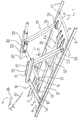
- the tilting device shown in FIG. 1, is fixed to the chassis of a carrier vehicle by means of a false chassis 1 consisting of two lateral longitudinal elements 2, 3 with a fixed transverse cross member 4 and a cross member mobile transverse 5.
- Each of the transverse crosspieces 4, 5 is constituted by two telescopic parts 6,7 and 8, 9 respectively.
- Such a structure makes it possible to lower the width of the subframe 1 by welding a tubular element 10 on the lateral longitudinal element 3.
- the fixed transverse cross member 4 is provided with two lugs 13, 14 intended to maintain transverse axes 15, 16
- These transverse axes 15, 16 constitute two of the points of articulation of the compasses 17, 18.
- the compasses 17, 18 consist of two first branches 19, 20 movable on the one hand around the lower axes 15, 16 and on the other leaves around two of the upper axes 21, 22.
- the compasses 17, 18 further comprise a second pair of arms 23, 24 articulated around two lower axes 25, 26 cooperating with the movable transverse cross member 5, and around two upper axes 27, 28.
- the upper axes 21, 22 of the first compass branch 19, 20 and the upper axes 27, 28 of the second pair of branches 23, 24 are integral with two slides respectively 29, 30.
- the slides 29, 30 are movable longitudinally with respect to the loading platform not shown in the figure.
- the tilting device further comprises a hydraulic cylinder whose body 31 is fixed to the fixed transverse cross member 4 and the piston 32 of the cylinder acts on the movable transverse cross member 5.
- the locking element 33 is arranged parallel to said cylinder and is constituted an inner tube 34 connected to the movable transverse cross member 5 via the axis 25, and by an outer tube 35 connected to the fixed transverse cross member 4.
- a lock 36 is constituted by a cooperating rod, in the advanced position , with radial holes made in the inner tube 34. The displacement of the rod is controlled by a lever 36 via a cable 37.
- the present invention is in no way limited to the embodiments described by way of example.
- the upper axes 27, 28 of the second pair of branches 23, 24 can be fixed not on the sliders 29, 30 but on the first pair of branches respectively 19, 20.
- other sliding means that guide rails can be envisaged.
- the invention is not limited to the tilting of a loading platform but of course extends to the tilting of any means arranged on a carrier vehicle: tipper, trailer, special loading platform.
Landscapes
- Engineering & Computer Science (AREA)
- Transportation (AREA)
- Mechanical Engineering (AREA)
- Health & Medical Sciences (AREA)
- Public Health (AREA)
- Body Structure For Vehicles (AREA)
- Vehicle Body Suspensions (AREA)
- Spinning Or Twisting Of Yarns (AREA)
- Mounting And Adjusting Of Optical Elements (AREA)
- Eye Examination Apparatus (AREA)
- Vehicle Cleaning, Maintenance, Repair, Refitting, And Outriggers (AREA)
- Handcart (AREA)
Priority Applications (1)
| Application Number | Priority Date | Filing Date | Title |
|---|---|---|---|
| AT89440137T ATE81319T1 (de) | 1989-01-10 | 1989-12-19 | Kippvorrichtung einer laderampe. |
Applications Claiming Priority (2)
| Application Number | Priority Date | Filing Date | Title |
|---|---|---|---|
| FR8900221 | 1989-01-10 | ||
| FR8900221A FR2641504A1 (fr) | 1989-01-10 | 1989-01-10 | Dispositif de basculement d'un plateau de chargement |
Publications (2)
| Publication Number | Publication Date |
|---|---|
| EP0378034A1 true EP0378034A1 (de) | 1990-07-18 |
| EP0378034B1 EP0378034B1 (de) | 1992-10-07 |
Family
ID=9377584
Family Applications (1)
| Application Number | Title | Priority Date | Filing Date |
|---|---|---|---|
| EP89440137A Expired - Lifetime EP0378034B1 (de) | 1989-01-10 | 1989-12-19 | Kippvorrichtung einer Laderampe |
Country Status (5)
| Country | Link |
|---|---|
| US (1) | US5056624A (de) |
| EP (1) | EP0378034B1 (de) |
| AT (1) | ATE81319T1 (de) |
| DE (1) | DE68903166D1 (de) |
| FR (1) | FR2641504A1 (de) |
Cited By (2)
| Publication number | Priority date | Publication date | Assignee | Title |
|---|---|---|---|---|
| FR2686843A1 (fr) * | 1992-01-30 | 1993-08-06 | Jige Lohr Wreckers | Ensemble basculant-coulissant de chargement par traction a partir du sol et de transport, pour porteur routier. |
| CN110104569A (zh) * | 2019-06-10 | 2019-08-09 | 中鼎国际工程有限责任公司 | 一种市政管道用辅助安装的方法及设备 |
Families Citing this family (4)
| Publication number | Priority date | Publication date | Assignee | Title |
|---|---|---|---|---|
| US6010285A (en) * | 1997-10-03 | 2000-01-04 | Kar-Tainer International, Inc. | Collapsible vehicle transportation frame |
| US7360983B2 (en) * | 2003-04-04 | 2008-04-22 | Pate Buck A | Portable elevated vehicle display |
| FR2882352B1 (fr) * | 2005-02-23 | 2008-10-17 | Marolotest Soc Par Actions Sim | Banc elevateur pour l'entretien et la reparation de vehicules legers |
| US7275713B2 (en) * | 2005-06-15 | 2007-10-02 | The Boeing Company | Jack apparatus |
Citations (3)
| Publication number | Priority date | Publication date | Assignee | Title |
|---|---|---|---|---|
| US3623617A (en) * | 1970-04-20 | 1971-11-30 | Tridair Industries | Cargo-handling device having a tilt-adjusting system |
| FR2302883A1 (fr) * | 1975-03-05 | 1976-10-01 | Bertoncini Marcel | Dispositif de plateau de vehicules a positions et fonctions multiples |
| US4770592A (en) * | 1987-06-15 | 1988-09-13 | Winter Charles M | Transport truck for vehicles |
Family Cites Families (6)
| Publication number | Priority date | Publication date | Assignee | Title |
|---|---|---|---|---|
| US3173644A (en) * | 1965-03-16 | Safety prop | ||
| FR1164042A (fr) * | 1956-12-28 | 1958-10-06 | Fruehauf France | Dispositif pour l'arrimage d'une semi-remorque sur un wagon de chemin de fer |
| US3183037A (en) * | 1963-03-08 | 1965-05-11 | Robert B Reichert | Safety supporting device for dump truck bodies |
| US3317004A (en) * | 1966-01-14 | 1967-05-02 | Dover Corp | Safety device for a vehicle lift |
| DE1618169A1 (de) * | 1967-05-31 | 1970-12-10 | Basf Ag | Substituierte Phenylcarbaminsaeureureidophenylester |
| US3844421A (en) * | 1972-12-21 | 1974-10-29 | E Nielsen | Apparatus for lifting and tilting automobiles |
-
1989
- 1989-01-10 FR FR8900221A patent/FR2641504A1/fr not_active Withdrawn
- 1989-12-19 EP EP89440137A patent/EP0378034B1/de not_active Expired - Lifetime
- 1989-12-19 AT AT89440137T patent/ATE81319T1/de not_active IP Right Cessation
- 1989-12-19 DE DE8989440137T patent/DE68903166D1/de not_active Expired - Lifetime
-
1990
- 1990-01-09 US US07/462,199 patent/US5056624A/en not_active Expired - Fee Related
Patent Citations (3)
| Publication number | Priority date | Publication date | Assignee | Title |
|---|---|---|---|---|
| US3623617A (en) * | 1970-04-20 | 1971-11-30 | Tridair Industries | Cargo-handling device having a tilt-adjusting system |
| FR2302883A1 (fr) * | 1975-03-05 | 1976-10-01 | Bertoncini Marcel | Dispositif de plateau de vehicules a positions et fonctions multiples |
| US4770592A (en) * | 1987-06-15 | 1988-09-13 | Winter Charles M | Transport truck for vehicles |
Cited By (2)
| Publication number | Priority date | Publication date | Assignee | Title |
|---|---|---|---|---|
| FR2686843A1 (fr) * | 1992-01-30 | 1993-08-06 | Jige Lohr Wreckers | Ensemble basculant-coulissant de chargement par traction a partir du sol et de transport, pour porteur routier. |
| CN110104569A (zh) * | 2019-06-10 | 2019-08-09 | 中鼎国际工程有限责任公司 | 一种市政管道用辅助安装的方法及设备 |
Also Published As
| Publication number | Publication date |
|---|---|
| DE68903166D1 (de) | 1992-11-12 |
| US5056624A (en) | 1991-10-15 |
| ATE81319T1 (de) | 1992-10-15 |
| EP0378034B1 (de) | 1992-10-07 |
| FR2641504A1 (fr) | 1990-07-13 |
Similar Documents
| Publication | Publication Date | Title |
|---|---|---|
| EP0517634B1 (de) | Hebevorrichtung mit vertikaler Verlagerung einer Ladetragebene | |
| FR2644736A1 (fr) | Nouveau hayon pour le chargement de marchandises dans un vehicule | |
| EP0905083B1 (de) | Wagen mit Hubmast, geeignet zur Montage an das Ende eines Transportfahrzeugs | |
| EP0479653B1 (de) | Montagevorrichtung für eine parallel zum Chassis eines Fahrzeuges ausfahrbare Ladebordwand | |
| CA2158232C (fr) | Chariot de manutention motorise a bras telescopique | |
| EP0378034B1 (de) | Kippvorrichtung einer Laderampe | |
| EP0571240A1 (de) | Träger zur Mitnahme eines Gabelstaplers am Ende einer Laderampe eines Lastkraftwagens, Mitnahmevorrichtung für diesen Träger und Lastkraftwagen mit dieser Vorrichtung | |
| EP0490798B1 (de) | Kran, insbesondere für die Handhabung | |
| EP3070203B1 (de) | Be-, entlade- und aufsetzsystem einer schienenweiche auf ein bahngleis | |
| EP0493284B1 (de) | Schwenkbetätiger zum Ausführen aller geradlinigen oder rotierenden Bewegungen | |
| EP0623488A1 (de) | Einrichtung zum Stabilsieren einer lasttragenden Fahrzeugladefläche | |
| FR2730681A1 (fr) | Plateau mobile pour vehicule porte-plateau destine au chargement et au transport d'objets, notamment d'automobiles | |
| FR2546828A2 (fr) | Vehicule porteur a plateau mobile et a dispositif telescopique de levage/tractage | |
| EP0399882A1 (de) | Verfahren zum Einbauen einer Handbremse in ein Automobil und System zur Durchführung dieses Verfahrens | |
| FR2786454A1 (fr) | Hayon elevateur retractable | |
| EP4086137B1 (de) | Werkzeug zum bewegen einer anhängerkupplung eines schienenfahrzeugs, entsprechende anordnung und entsprechendes anwendungsverfahren | |
| FR2786455A1 (fr) | Hayon elevateur pour vehicule | |
| WO2023228071A1 (fr) | Porte pour véhicule de voirie | |
| EP1263623B1 (de) | Hebebühne, die unter einem fahrzeugboden oder dergleichem einklappbar ist | |
| EP0579589A1 (de) | Auf einem Sattelanhänger oder auf einem Anhänger versetzbarer Kran | |
| FR2790747A1 (fr) | Vis a grain, elevatrice | |
| FR2473965A1 (fr) | Dispositif de guidage pour le chargement et le dechargement d'un conteneur sur le chassis d'un vehicule | |
| FR2801014A1 (fr) | Dispositif elevateur de benne a bras articules | |
| FR2588221A1 (fr) | Dispositif d'actionnement, notamment pour vehicule a plateau basculant | |
| WO2005035306A2 (fr) | Dispositif de blocage d'au moins une charge sur une partie de chassis d'un moyen de transport |
Legal Events
| Date | Code | Title | Description |
|---|---|---|---|
| PUAI | Public reference made under article 153(3) epc to a published international application that has entered the european phase |
Free format text: ORIGINAL CODE: 0009012 |
|
| AK | Designated contracting states |
Kind code of ref document: A1 Designated state(s): AT BE CH DE ES GB IT LI LU NL SE |
|
| 17P | Request for examination filed |
Effective date: 19910110 |
|
| 17Q | First examination report despatched |
Effective date: 19911008 |
|
| GRAA | (expected) grant |
Free format text: ORIGINAL CODE: 0009210 |
|
| AK | Designated contracting states |
Kind code of ref document: B1 Designated state(s): AT BE CH DE ES GB IT LI LU NL SE |
|
| PG25 | Lapsed in a contracting state [announced via postgrant information from national office to epo] |
Ref country code: IT Free format text: LAPSE BECAUSE OF FAILURE TO SUBMIT A TRANSLATION OF THE DESCRIPTION OR TO PAY THE FEE WITHIN THE PRE;WARNING: LAPSES OF ITALIAN PATENTS WITH EFFECTIVE DATE BEFORE 2007 MAY HAVE OCCURRED AT ANY TIME BEFORE 2007. THE CORRECT EFFECTIVE DATE MAY BE DIFFERENT FROM THE ONE RECORDED.SCRIBED TIME-LIMIT Effective date: 19921007 Ref country code: SE Effective date: 19921007 Ref country code: GB Effective date: 19921007 Ref country code: NL Effective date: 19921007 Ref country code: ES Free format text: THE PATENT HAS BEEN ANNULLED BY A DECISION OF A NATIONAL AUTHORITY Effective date: 19921007 Ref country code: DE Effective date: 19921007 Ref country code: AT Effective date: 19921007 |
|
| REF | Corresponds to: |
Ref document number: 81319 Country of ref document: AT Date of ref document: 19921015 Kind code of ref document: T |
|
| REF | Corresponds to: |
Ref document number: 68903166 Country of ref document: DE Date of ref document: 19921112 |
|
| PG25 | Lapsed in a contracting state [announced via postgrant information from national office to epo] |
Ref country code: LU Free format text: LAPSE BECAUSE OF NON-PAYMENT OF DUE FEES Effective date: 19921231 Ref country code: BE Effective date: 19921231 Ref country code: CH Effective date: 19921231 Ref country code: LI Effective date: 19921231 |
|
| NLV1 | Nl: lapsed or annulled due to failure to fulfill the requirements of art. 29p and 29m of the patents act | ||
| GBV | Gb: ep patent (uk) treated as always having been void in accordance with gb section 77(7)/1977 [no translation filed] |
Effective date: 19921007 |
|
| BERE | Be: lapsed |
Owner name: S.A. JIGE LOHR WRECKERS Effective date: 19921231 |
|
| PLBE | No opposition filed within time limit |
Free format text: ORIGINAL CODE: 0009261 |
|
| STAA | Information on the status of an ep patent application or granted ep patent |
Free format text: STATUS: NO OPPOSITION FILED WITHIN TIME LIMIT |
|
| REG | Reference to a national code |
Ref country code: CH Ref legal event code: PL |
|
| 26N | No opposition filed |