EP0490798B1 - Kran, insbesondere für die Handhabung - Google Patents
Kran, insbesondere für die Handhabung Download PDFInfo
- Publication number
- EP0490798B1 EP0490798B1 EP91440107A EP91440107A EP0490798B1 EP 0490798 B1 EP0490798 B1 EP 0490798B1 EP 91440107 A EP91440107 A EP 91440107A EP 91440107 A EP91440107 A EP 91440107A EP 0490798 B1 EP0490798 B1 EP 0490798B1
- Authority
- EP
- European Patent Office
- Prior art keywords
- jib
- actuator
- way
- post
- fork
- Prior art date
- Legal status (The legal status is an assumption and is not a legal conclusion. Google has not performed a legal analysis and makes no representation as to the accuracy of the status listed.)
- Expired - Lifetime
Links
- 230000002093 peripheral effect Effects 0.000 claims description 2
- 238000007688 edging Methods 0.000 claims 1
- 230000001960 triggered effect Effects 0.000 claims 1
- 210000000707 wrist Anatomy 0.000 claims 1
- 230000000284 resting effect Effects 0.000 description 4
- 238000003754 machining Methods 0.000 description 2
- 238000000034 method Methods 0.000 description 2
- 230000000149 penetrating effect Effects 0.000 description 2
- 230000006978 adaptation Effects 0.000 description 1
- 125000004122 cyclic group Chemical group 0.000 description 1
- 230000007423 decrease Effects 0.000 description 1
- 230000006866 deterioration Effects 0.000 description 1
- 230000035939 shock Effects 0.000 description 1
Images

Classifications
-
- B—PERFORMING OPERATIONS; TRANSPORTING
- B66—HOISTING; LIFTING; HAULING
- B66C—CRANES; LOAD-ENGAGING ELEMENTS OR DEVICES FOR CRANES, CAPSTANS, WINCHES, OR TACKLES
- B66C23/00—Cranes comprising essentially a beam, boom, or triangular structure acting as a cantilever and mounted for translatory of swinging movements in vertical or horizontal planes or a combination of such movements, e.g. jib-cranes, derricks, tower cranes
- B66C23/54—Cranes comprising essentially a beam, boom, or triangular structure acting as a cantilever and mounted for translatory of swinging movements in vertical or horizontal planes or a combination of such movements, e.g. jib-cranes, derricks, tower cranes with pneumatic or hydraulic motors, e.g. for actuating jib-cranes on tractors
-
- B—PERFORMING OPERATIONS; TRANSPORTING
- B66—HOISTING; LIFTING; HAULING
- B66C—CRANES; LOAD-ENGAGING ELEMENTS OR DEVICES FOR CRANES, CAPSTANS, WINCHES, OR TACKLES
- B66C23/00—Cranes comprising essentially a beam, boom, or triangular structure acting as a cantilever and mounted for translatory of swinging movements in vertical or horizontal planes or a combination of such movements, e.g. jib-cranes, derricks, tower cranes
- B66C23/62—Constructional features or details
- B66C23/84—Slewing gear
- B66C23/86—Slewing gear hydraulically actuated
Definitions
- the present invention relates to the field of equipment for handling in general and transporting logs in particular, in particular cranes fitted to road tractors combined with mobile crews, trailers or cranes mounted at a fixed position and relates to a crane, especially for handling.
- the cranes fitted to logging equipment tractors or other road vehicles or trailers or even mounted on a fixed station are generally jib cranes made of several foldable elements, of which the second element at least is foldable by actuation by means of 'A cylinder arranged under the first element and acting on the lower part of said second element.
- the lower boom element is articulated on the end of a rotary barrel and is actuated by at least one external jack resting by its yoke on said barrel, which is mounted on the chassis of the vehicle or on a chassis fixed to the by means of a crown or of a ball or roller turret provided with a cooperating toothed crown, for driving the barrel in rotation, either with racks actuated by jacks, or with a pinion driven by a hydraulic motor .
- the rotary drum directly collects the torque of the load transmitted by the boom in addition to the rotation torque.
- the jib operating cylinder is disposed outside of the latter and is articulated on the upper part of the barrel at a level different from that of the articulation of the jib, so that when lifting a load. the lifting torque decreases.
- the barrel being mounted in a vertical body, there is no special mounting device of the fixing type on a box.
- the present invention aims to overcome these drawbacks.
- a crane in particular for handling, essentially constituted by a jib, mounted in an articulated manner, by means of flanges, integral with the lower end of the jib, with a projection on the upper part of a rotary device in the form of a sleeve and an axis on a barrel, mounted on a vehicle or fixed chassis, the boom being provided, at its free end for mounting a hook, a grapple or other tool, a rotary actuator for the latter, the rotary device being integral with a part passing through the barrel and being actuated in rotation by means of a rotary actuator cooperating with the lower part of said part, the jib being actuated, for lifting, by at least one jack connected to the jib and to the rotary device, characterized in that the rotary device has a larger outside diameter than that of the barrel and is guided on the longitudinal surface and on the transverse surface of said barrel by guide elements, the projection of the rotary device comprising a
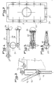
- the crane in particular for handling, is essentially constituted by a boom 1 and by a drum 2 for receiving the boom mounted on a vehicle or fixed chassis, the barrel 2 being fixed on the chassis and the boom 1 being articulated on a rotary device 3 guided on or in the barrel 2.
- This device 3 is provided with a part 4 passing through the barrel 2 and cooperating at its lower part with a rotary actuator 5 of the arrow 1.
- the latter can be fitted, at its free end for mounting a hook, with a grapple or another tool, a rotary actuator similar to the actuator 5, not shown, for directing the products handled.
- the arrow 1 is articulated on the rotary device 3 by means of flanges 6 and of an axis 7 and is actuated by means of at least one jack 8 mounted at articulation by its yoke in the size of the rotary device 3, substantially level with the hinge pin 7, the jack 8 penetrating the arrow 1 and being articulated on the latter so as to obtain a substantially constant lever arm.
- Such an embodiment allows minimum space at the joint and obtaining good protection of the jack 8 against possible shocks caused by parts handled.
- the actuation of the boom 1 can also be achieved by means of two jacks, namely a pushing jack 8 and a pulling cylinder 9 connected by its rod to a rear extension of the arrow 1 and mounted at articulation by its yoke on the rotary device 3.
- the force of the cylinders 8 and 9 may be less and it is possible to use smaller cylinders.
- the actuation of the rear end of the boom 1 can also be achieved by a thrust cylinder 12 connected by its piston rod to a yoke 13 of the rotary device 3 and by its yoke, by means of an axis 14, at the end of a fork 15 or of a pair of rods connected by its other end to said rear end of arrow 1, the connecting axis of the fork or the rods to the jack 12 cooperating with vertical guides 16 integral with the device 3.
- the actuation of the boom 1 can be carried out by means of two thrust jacks, the rear jack 12 being supported by its rod piston on the yoke 13 and sliding along the device by pulling on the fork or the rods 15, so that the force of the jacks necessary for a given lifting power can be significantly reduced.
- the rotary device 3 (FIG. 1) can be constituted in the form of a sleeve mounted on the end of the barrel 2, guided on the latter by means of plain, ball, roller or needle bearings 17 and resting on said barrel 2 by means of a stopper 18 with needles or rollers, this sleeve being provided at its upper part with the articulation yoke (s) of arrow 1 and the actuating cylinder of the latter.
- the device 3 can also be in the form of a sleeve inserted into the barrel 2, guided by means of bearings 19 and provided at its upper part with a cooperating support plate 20 with a stop 21 mounted on the end of the barrel 2, this plate 20 carrying the articulation yoke (s) of the arrow 1 and its actuating cylinder and being able to be provided with a vertical return 22 for receiving a pulling jack, this return 22 resting on the barrel by means of a roller 23 or the like (FIG. 2) or being supported by oblique gussets resting under the plate 20.
- the rotary actuator 5 of the boom 1 may advantageously be constituted, as shown in Figures 1 and 4 of the accompanying drawings, by a toothed ring for chain or by a grooved ring for cable 24, fixed to the lower end of the piece 4 passing through the barrel 2 and secured to the device 3 and cooperating with a chain or a cable 25, the two ends of which are secured to a wall of a box 26 for receiving the actuator 5, said chain or said cable 25 being guided, in addition, on two chain sprockets or grooved pulleys 27 rotatably mounted on the end of the rods piston of two cylinders 28 parallel or in opposition, the axes of connection of the pinions or wheels 27 to said piston rods being guided in corresponding parallel grooves (not shown) provided in the box 26.
- a toothed ring for chain or by a grooved ring for cable 24 fixed to the lower end of the piece 4 passing through the barrel 2 and secured to the device 3 and cooperating with a chain or a cable 25, the two ends of which are
- the choice of the diameter of the crown 24 and the power of the jacks can be made as a function of the desired torque and / or as a function of the useful angle of rotation necessary for the proper functioning of the crane.
- Figures 5 and 6 show an alternative embodiment of the invention, in which the rotary actuator 5 is connected to the lower end of the part 4 penetrating into the casing 26 and is constituted by a crankshaft 29, the crank pins of which are arranged at regular intervals, are advantageously at least three in number and are each actuated by a jack 30, the jacks 30 being controlled by means of a programmable automation or a distributor with drawers.
- a programmable automation or a distributor with drawers a programmable automation or a distributor with drawers.
- the part 4 connecting the device 3 to the actuator 5 is advantageously produced in the form of a hollow tube opening at the upper end of the device 3 or in a chamber open at the upper end of said device 3 and cooperating in its part lower with a crown 24 with central recess.
- a part 4 allows the passage of the supply pipes of the various cylinders by means of flexible hoses or a rotary oil distributor and thus avoiding a risk of deterioration of the latter during handling.
- the barrel 2 is fixed at its lower part to the box 26 of the actuator 5, this box being provided in its lower part with a peripheral flange 31 provided with holes 32 for passage of flanges or tightening bolts on the chassis of the carrier vehicle. These holes 32 are arranged on the rim 31 according to the needs of the assembly.
- the invention it is possible to produce a crane, in particular for handling, of simple constitution, making it possible to eliminate the fragile zones currently existing on known cranes and to better protect the various jacks, as well as their piping. 'food.
- the invention makes it possible, with equal dimensioning of the jacks, to produce cranes of greater power or even, for a given power, to considerably reduce the cost price of such a crane.
Landscapes
- Engineering & Computer Science (AREA)
- Mechanical Engineering (AREA)
- Jib Cranes (AREA)
- Organic Low-Molecular-Weight Compounds And Preparation Thereof (AREA)
- Control And Safety Of Cranes (AREA)
- Load-Engaging Elements For Cranes (AREA)
Claims (12)
- Kran, insbesondere für die Handhabung, im wesentlichen bestehend aus einem Ausleger (1), der mittels am unteren Ende des Auslegers (1) befestigter Flansche (6 )und einer Achse (7) an eine Aufbau einer Hülse am oberen Ende eines drehbaren Bauelements (3) einer Säule (2) angelenkt ist, die auf dem Fahrgestell eines Fahrzeuges befestigt oder ortsfest ist, wobei der Ausleger an seinem freien Montageende einen Haken, einen Greifer oder ein anderes Werkzeug und für letzteres eine Drehbetätigung aufweist, wobei das drehbare Bauelement(3)an einem die Säule (2) durchragenden Bauteil (4) befestigt ist und mittels einer Drehbetätigung (5) in Drehung versetzt wird, die mit dem unteren Teil des Bauteils (4) zusammenwirkt, und der Ausleger (1) zum Heben durch wenigstens eine Kolben-Zylinder-Einheit (8) betätigt wird, die mit dem Ausleger (1) und mit dem drehbaren Bauelement (3) verbunden ist, dadurch gekennzeichnet, daß das drehbare Bauelement (3) einen größeren äußeren Durchmesser als die Säule (2) besitzt und auf der Längsfläche sowie der Querfläche der Säules (2) mittels Führungselementen (17, 18, 19) geführt ist, wobei der Aufbau des drehbaren Bauelements (3) ein Paar im wesentlichen auf gleicher Höhe angeordneter Bohrungen aufweist, die zum Teil als Aufnahme für die Schwenkachse (7) des Auslegers (1) und zum anderen Teil der Befestigung des unteren Endes der Kolben-Zylinder-Einheit (8) dienen.
- Kran nach Anspruch 1, dadurch gekennzeichnet, daß die Kolben-Zylinder-Einheit (8), die den Ausleger (1) betätigt und mit ihrem Gabelgelenk an dem Aufbau des oberen Teils des drehbaren Bauelements (3) angelenkt ist, in den Ausleger (1) hineinragt und mit diesem in der Weise gelenkig verbunden ist, daß ein im wesentlichen gleichbleibender Hebelarm erreicht wird.
- Kran nach einem der Ansprüche 1 und 2, dadurch gekennzeichnet, daß der Ausleger (1) mittels zweier Kolben-Zylinder-Einheiten betätigt wird, und zwar einer drückenden Kolben-Zylinder-Einheit (8) und einer ziehenden Kolben-Zylinder-Einheit (9), die mit ihrer Kolbenstange mit einer hinteren Verlängerung des Auslegers (1) verbunden ist und mit ihrem Gabelgelenk am drehbaren Bauelement (3) angelenkt ist.
- Kran nach Anspruch 3, dadurch gekennzeichnet, daß die Kolbenstangen der Kolben-Zylinder-Einheiten (8 und 9) in einem in dem Ausleger (1) angeordneten Schlitten (10) angelenkt sind, wobei sich der Schlitten (10) in der Arbeitsstellung und in der Ruhestellung mittels einer automatischen Verriegelung (11) blockieren läßt.
- Kran nach Anspruch 2, dadurch gekennzeichnet, daß das hintere Ende des Auslegers (1) mittels einer drückenden Kolben-Zylinder-Einheit (12) betätigt wird, deren Kolbenstange an einem Gabelgelenk (13) der drehbaren Baueinheit (3) und deren Gabelgelenk über eine Achse (14) am Ende einer Gabel (15) oder einem Schwingarmpaar angelenkt ist, das mit seinem anderen Ende mit dem hinteren Ende des Auslegers (1) verbunden ist, wobei die Verbindungsachse der Gabel oder des Schwingarmpaares mit der Kolben-Zylinder-Einheit (12) mit senkrechten Führungen (16) zusammenwirkt, die an dem Bauelement (3) befestigt sind.
- Kran nach Anspruch 2 oder 5, dadurch gekennzeichnet, daß der Ausleger (1) mittels zweier drückenden Kolben-Zylinder-Einheiten betätigt wird, wobei sich die hintere Kolben-Zylinder-Einheit (12) mittels ihrer Kolbenstange auf dem Gabelgelenk (13) abstützt, am Bauelement entlanggleitet und dabei an der Gabel oder den Schwingarmen (15) zieht.
- Kran nach Anspruch 1, dadurch gekennzeichnet, daß das drehbare Bauelement (3) als Hülse ausgebildet ist, die auf dem Ende der Säule (2) angeordnet und darauf mittels Gleitlagern (17), Kugellagern, Rollenlagern oder Nadellagern geführt ist und sich auf der Säule (2) mittels eines Drucklagers (18) mit Nadeln oder Rollen abstützt, wobei diese Hülse an ihrem Oberteil mit dem oder den Gabelgelenk(en) des Auslegers (1) und der Kolben-Zylinder-Einheit zur Betätigung des Auslegers versehen ist.
- Kran nach Anspruch 1, dadurch gekennzeichnet, daß das Bauelement (3) eine in die Säule (2) eingesetzte Hülse besitzt, die mittels Lager (19) geführt ist und an ihrem Oberteil eine Druckplatte (20) aufweist, die mit einem auf dem Ende der Säule (2) angeordneten Drucklager (21) zusammenwirkt, wobei die Druckplatte (20) das oder die Gabelgelenk(e) des Auslegers (1) und der Kolben-Zylinder-Einheit zu seiner Betätigung tragen und mit einer senkrechten Abwinklung (22) zur Anlenkung einer ziehenden Kolben-Zylinder-Einheit versehen ist, und wobei sich diese Abwinklung (22) auf der Säule unter Zwischenschaltung einer Rolle (23) od.dgl. abstützt oder mittels schräger Eckstücke, die sich auf der Druckplatte (20) abstützen, versteift ist.
- Kran nach Anspruch 1, dadurch gekennzeichnet, daß die Drehbetätigung (5) des Auslegers (1) vorteilhafterweise aus einem Zahnkranz für eine Kette oder aus einem Rillenrad (24) für ein Seil (25) besteht, der oder das am unteren Ende des Bauteils (4), das durch die Säule (2) hindurch verläuft, befestigt und mit dem drehbaren Bauelement (3) verbunden ist sowie mit einer Kette oder einem Seil (25) zusammenwirkt, deren beiden Enden an einer Wand eines Gehäuses (26) zur Aufnahme der Drehbetätigung (5) befestigt sind, wobei die Kette oder das Seil (25) zusätzlich mittels zweier Kettenzahnräder oder zweier Seilrollen (27) geführt ist, die drehbar auf dem Ende der Kolbenstangen der beiden parallelen oder entgegengesetzten Kolben-Zylinder-Einheiten (28) angeordnet sind, und wobei die Verbindungsachsen der Zahnräder (27) mit den Kolbenstangen in parallelen, entsprechenden Schlitzen in dem Kasten (26) geführt sind.
- Kran nach Anspruch 1, dadurch gekennzeichnet, daß die Drehbetätigung (5) mit dem unteren Ende des Bauteils (4), das in das Gehäuse (26) hineinragt, verbunden ist und als Kurbelwelle (29) ausgebildet ist, die vorteilhafterweise drei in regelmäßigen Abständen angeordnete Hubzapfen aufweist, von denen jeder durch eine Kolben-Zylinder-Einheit (30) beaufschlagt wird, wobei diese Kolben-Zylinder-Einheiten (30) mittels einer programmierbaren, automatischen Vorrichtung oder eines Steuerverteilers mit Schiebern angesteuert werden.
- Kran nach einem der Ansprüche 1, 9 und 10, dadurch gekennzeichnet, daß das Bauteil (4), das das drehbare Bauelement (3) mit der Drehbetätigung (5) verbindet, vorteilhafterweise als Hohlrohr ausgebildet ist, das am oberen Ende des Bauelements (3) oder in einer offenen Kammer am oberen Ende des Bauteils (3) endet und an seinem unteren Ende mit einem Rad (24) mit einer mittigen Öffnung zusammenwirkt.
- Kran nach Anspruch 1, dadurch gekennzeichnet, daß die Säule (2) mit ihrem unteren Ende an dem Gehäuse (26) der Drehbetätigung (5) befestigt ist, wobei dieses Gehäuse (26) an seinem unteren Teil mit einem umlaufenden Vorsprung (31) versehen ist, der mit Durchgangsbohrungen für Befestigungsschellen oder Spannbolzen zum Verbinden mit dem Fahrgestell des den Kran tragenden Fahrzeugs versehen ist.
Applications Claiming Priority (2)
| Application Number | Priority Date | Filing Date | Title |
|---|---|---|---|
| FR9015888A FR2670477B1 (fr) | 1990-12-14 | 1990-12-14 | Grue, en particulier pour la manutention. |
| FR9015888 | 1990-12-14 |
Publications (3)
| Publication Number | Publication Date |
|---|---|
| EP0490798A2 EP0490798A2 (de) | 1992-06-17 |
| EP0490798A3 EP0490798A3 (en) | 1993-02-17 |
| EP0490798B1 true EP0490798B1 (de) | 1996-03-06 |
Family
ID=9403386
Family Applications (1)
| Application Number | Title | Priority Date | Filing Date |
|---|---|---|---|
| EP91440107A Expired - Lifetime EP0490798B1 (de) | 1990-12-14 | 1991-12-12 | Kran, insbesondere für die Handhabung |
Country Status (9)
| Country | Link |
|---|---|
| US (1) | US5282714A (de) |
| EP (1) | EP0490798B1 (de) |
| JP (1) | JPH06211493A (de) |
| AT (1) | ATE134977T1 (de) |
| CA (1) | CA2057562A1 (de) |
| DE (1) | DE69117695T2 (de) |
| FI (1) | FI97882C (de) |
| FR (1) | FR2670477B1 (de) |
| NO (1) | NO304879B1 (de) |
Families Citing this family (8)
| Publication number | Priority date | Publication date | Assignee | Title |
|---|---|---|---|---|
| US5393193A (en) * | 1992-05-18 | 1995-02-28 | Dagg; Stuart A. | Vehicle for transport and placement of grave headstones |
| PL182893B1 (pl) * | 1995-03-31 | 2002-03-29 | Ross Allan Simpson | Urządzenie do załadunku i rozładunku kontenerów na pojazdy mechaniczne |
| US6305678B1 (en) | 2000-06-02 | 2001-10-23 | Hammersmith Mfg. & Sales, Inc. | Welder positioner |
| US20090060685A1 (en) * | 2007-08-30 | 2009-03-05 | Howard Godfrey | All-Terrain Log Forwarder |
| DE102010023275B4 (de) * | 2010-06-10 | 2022-05-12 | Liebherr-Werk Ehingen Gmbh | Verfahren zum Verfahren von Großkranen im aufgerüsteten System und System zum Durchführen dieses Verfahrens |
| US20120085984A1 (en) * | 2010-10-08 | 2012-04-12 | Daya Arvind A | Gravity energy storage and generating device |
| GB201117251D0 (en) * | 2011-10-05 | 2011-11-16 | Autochair Ltd | Hoist mechanism |
| CN102653377B (zh) * | 2012-01-05 | 2014-06-04 | 中联重科股份有限公司 | 随车起重机和随车起重运输车 |
Family Cites Families (16)
| Publication number | Priority date | Publication date | Assignee | Title |
|---|---|---|---|---|
| DE1010463B (de) * | 1955-07-25 | 1957-06-13 | Weserhuette Ag Eisenwerk | Drehwerk fuer hydraulisch getriebene Bagger, Krane od. dgl. |
| US2966752A (en) * | 1955-09-06 | 1961-01-03 | Walter G Wampach | Cranes |
| US3032206A (en) * | 1960-02-23 | 1962-05-01 | Humboldt Company | Mobilized lifting and loading boom |
| NL111741C (de) * | 1960-08-16 | |||
| US3270899A (en) * | 1964-04-17 | 1966-09-06 | Baldwin Lima Hamilton Corp | Load handling vehicle |
| FR1418936A (fr) * | 1964-10-06 | 1965-11-26 | Madeleine Atel | Potence pivotante pour véhicule utilitaire, tel que camion ou autre |
| US3306442A (en) * | 1964-11-02 | 1967-02-28 | George C Devol | Multi-program apparatus |
| DE1269912B (de) * | 1966-01-26 | 1968-06-06 | Atlas Mak Maschb G M B H | Ladebaumlagerung, insbesondere fuer Schiffe |
| US3543944A (en) * | 1967-06-05 | 1970-12-01 | Frank G Woodside | Vehicle mounted hoist |
| US3533515A (en) * | 1968-09-03 | 1970-10-13 | Baker Equipment Eng Co | Boom structure for utility trucks and the like |
| AT301800B (de) * | 1970-03-03 | 1972-09-25 | Hermann Beimrohr Ing | Ladekran für Lastkraftwagen od.dgl. |
| US4172684A (en) * | 1978-01-30 | 1979-10-30 | Lee C. Moore Corporation | Floor level pipe handling apparatus |
| US4373853A (en) * | 1980-07-23 | 1983-02-15 | The United States Of America As Represented By The Secretary Of Agriculture | Log handling machine |
| AT371788B (de) * | 1981-02-11 | 1983-07-25 | Penz Rochus | Schwenkantrieb fuer die saeule eines drehkranes |
| US4373953A (en) * | 1981-04-06 | 1983-02-15 | Tenneco Chemicals, Inc. | Surface-coating compositions containing polyvalent metal salts of hydroxybenzoic acid esters |
| US4861224A (en) * | 1988-06-14 | 1989-08-29 | Hi-Ranger, Inc. | Aerial lift including overload sensing system |
-
1990
- 1990-12-14 FR FR9015888A patent/FR2670477B1/fr not_active Expired - Fee Related
-
1991
- 1991-12-12 AT AT91440107T patent/ATE134977T1/de not_active IP Right Cessation
- 1991-12-12 US US07/804,715 patent/US5282714A/en not_active Expired - Fee Related
- 1991-12-12 CA CA002057562A patent/CA2057562A1/fr not_active Abandoned
- 1991-12-12 DE DE69117695T patent/DE69117695T2/de not_active Expired - Fee Related
- 1991-12-12 EP EP91440107A patent/EP0490798B1/de not_active Expired - Lifetime
- 1991-12-13 FI FI915871A patent/FI97882C/fi active IP Right Grant
- 1991-12-13 NO NO914940A patent/NO304879B1/no not_active IP Right Cessation
- 1991-12-14 JP JP3351975A patent/JPH06211493A/ja active Pending
Also Published As
| Publication number | Publication date |
|---|---|
| FI97882B (fi) | 1996-11-29 |
| FR2670477B1 (fr) | 1995-07-28 |
| JPH06211493A (ja) | 1994-08-02 |
| EP0490798A2 (de) | 1992-06-17 |
| FI915871A0 (fi) | 1991-12-13 |
| DE69117695D1 (de) | 1996-04-11 |
| NO914940L (no) | 1992-06-15 |
| NO304879B1 (no) | 1999-03-01 |
| EP0490798A3 (en) | 1993-02-17 |
| DE69117695T2 (de) | 1996-10-10 |
| ATE134977T1 (de) | 1996-03-15 |
| CA2057562A1 (fr) | 1992-06-15 |
| FI915871A7 (fi) | 1992-06-15 |
| NO914940D0 (no) | 1991-12-13 |
| FR2670477A1 (fr) | 1992-06-19 |
| FI97882C (fi) | 1997-03-10 |
| US5282714A (en) | 1994-02-01 |
Similar Documents
| Publication | Publication Date | Title |
|---|---|---|
| EP0006076B1 (de) | Hebegerät mit freibeweglichem Korb zum Erklettern eines Mastes | |
| EP0490798B1 (de) | Kran, insbesondere für die Handhabung | |
| EP0701963B1 (de) | Motorhubwagen mit teleskopischem Arm | |
| FR2667550A1 (fr) | Ensemble de montage d'un hayon elevateur retractable parallelement au chassis d'un vehicule. | |
| EP0100926B1 (de) | Fahrzeug zur Handhabung von Materialien mit orientierbarem Ausleger und eingebautem Stabilisiergestell | |
| EP1103512B1 (de) | Verstellbarer Kranausleger mit selbsttätiger Gewichtsausgleichsvorrichtung | |
| EP0493284B1 (de) | Schwenkbetätiger zum Ausführen aller geradlinigen oder rotierenden Bewegungen | |
| CH630809A5 (en) | Elevator with autonomous cab for climbing along a mast | |
| EP0892758B1 (de) | Vorrichtung zum ziehen und drucken von einer last in eine gewisse ebene | |
| EP1953112B1 (de) | Hubgerät | |
| FR2615157A1 (fr) | Tracteur perfectionne notamment pour semi-remorque | |
| FR2750411A1 (fr) | Grue de chantier a pivot inferieur comprenant un chariot | |
| EP0226933B1 (de) | Werkzeug zum Anziehen und Lösen einer Rohrverbindung | |
| FR2694316A1 (fr) | Chargeur-excavateur-élévateur. | |
| FR3110104A1 (fr) | dispositif d’interface pour bras rotatif robotisé , procédé de commande , dispositif d’intervention | |
| EP2010720B1 (de) | Vorrichtung zur verbindung eines werkzeugs mit dem ausleger einer maschine, wie zum beispiel einem hydraulikbagger | |
| FR2641266A1 (fr) | Dispositif pour la mise a l'aplomb vertical de poteaux, piliers ou analogues | |
| FR2754484A1 (fr) | Perfectionnement pour dispositif de serrage du type comprenant un levier actionne par un piston | |
| FR2648122A1 (fr) | Dispositif de bras telescopique pour chariot elevateur | |
| EP3012219A1 (de) | Erdbewegungsvorrichtung, die an die förderplatte eines teleskopstaplers angepasst werden kann | |
| FR2537120A1 (fr) | Dispositif d'auto-alignement de conteneurs pour chariot de manutention | |
| EP1263623B1 (de) | Hebebühne, die unter einem fahrzeugboden oder dergleichem einklappbar ist | |
| WO2022106778A1 (fr) | Engin de manutention a bras telescopique | |
| BE906105A (fr) | Perfectionnements du dispositif de levage des vehicules compacts de manutention. | |
| EP1405953A1 (de) | Baumaschine mit Mitteln zum Heben des Auslegers |
Legal Events
| Date | Code | Title | Description |
|---|---|---|---|
| PUAI | Public reference made under article 153(3) epc to a published international application that has entered the european phase |
Free format text: ORIGINAL CODE: 0009012 |
|
| AK | Designated contracting states |
Kind code of ref document: A2 Designated state(s): AT BE CH DE DK ES GB GR IT LI LU NL SE |
|
| PUAL | Search report despatched |
Free format text: ORIGINAL CODE: 0009013 |
|
| AK | Designated contracting states |
Kind code of ref document: A3 Designated state(s): AT BE CH DE DK ES GB GR IT LI LU NL SE |
|
| 17P | Request for examination filed |
Effective date: 19930726 |
|
| 17Q | First examination report despatched |
Effective date: 19941107 |
|
| GRAA | (expected) grant |
Free format text: ORIGINAL CODE: 0009210 |
|
| AK | Designated contracting states |
Kind code of ref document: B1 Designated state(s): AT BE CH DE DK ES GB GR IT LI LU NL SE |
|
| PG25 | Lapsed in a contracting state [announced via postgrant information from national office to epo] |
Ref country code: NL Free format text: LAPSE BECAUSE OF FAILURE TO SUBMIT A TRANSLATION OF THE DESCRIPTION OR TO PAY THE FEE WITHIN THE PRESCRIBED TIME-LIMIT Effective date: 19960306 Ref country code: GR Free format text: LAPSE BECAUSE OF FAILURE TO SUBMIT A TRANSLATION OF THE DESCRIPTION OR TO PAY THE FEE WITHIN THE PRESCRIBED TIME-LIMIT Effective date: 19960306 Ref country code: GB Effective date: 19960306 Ref country code: ES Free format text: THE PATENT HAS BEEN ANNULLED BY A DECISION OF A NATIONAL AUTHORITY Effective date: 19960306 Ref country code: DK Effective date: 19960306 |
|
| REF | Corresponds to: |
Ref document number: 134977 Country of ref document: AT Date of ref document: 19960315 Kind code of ref document: T |
|
| REF | Corresponds to: |
Ref document number: 69117695 Country of ref document: DE Date of ref document: 19960411 |
|
| ITF | It: translation for a ep patent filed | ||
| NLV1 | Nl: lapsed or annulled due to failure to fulfill the requirements of art. 29p and 29m of the patents act | ||
| GBV | Gb: ep patent (uk) treated as always having been void in accordance with gb section 77(7)/1977 [no translation filed] |
Effective date: 19960306 |
|
| PG25 | Lapsed in a contracting state [announced via postgrant information from national office to epo] |
Ref country code: LU Free format text: LAPSE BECAUSE OF NON-PAYMENT OF DUE FEES Effective date: 19961231 Ref country code: LI Effective date: 19961231 Ref country code: CH Effective date: 19961231 Ref country code: BE Effective date: 19961231 |
|
| PLBE | No opposition filed within time limit |
Free format text: ORIGINAL CODE: 0009261 |
|
| STAA | Information on the status of an ep patent application or granted ep patent |
Free format text: STATUS: NO OPPOSITION FILED WITHIN TIME LIMIT |
|
| 26N | No opposition filed | ||
| BERE | Be: lapsed |
Owner name: DIEBOLT REMY Effective date: 19961231 |
|
| REG | Reference to a national code |
Ref country code: CH Ref legal event code: PL |
|
| PGFP | Annual fee paid to national office [announced via postgrant information from national office to epo] |
Ref country code: AT Payment date: 20011214 Year of fee payment: 11 |
|
| PGFP | Annual fee paid to national office [announced via postgrant information from national office to epo] |
Ref country code: SE Payment date: 20011219 Year of fee payment: 11 |
|
| PGFP | Annual fee paid to national office [announced via postgrant information from national office to epo] |
Ref country code: DE Payment date: 20020221 Year of fee payment: 11 |
|
| PG25 | Lapsed in a contracting state [announced via postgrant information from national office to epo] |
Ref country code: AT Free format text: LAPSE BECAUSE OF NON-PAYMENT OF DUE FEES Effective date: 20021212 |
|
| PG25 | Lapsed in a contracting state [announced via postgrant information from national office to epo] |
Ref country code: SE Free format text: LAPSE BECAUSE OF NON-PAYMENT OF DUE FEES Effective date: 20021213 |
|
| PG25 | Lapsed in a contracting state [announced via postgrant information from national office to epo] |
Ref country code: DE Free format text: LAPSE BECAUSE OF NON-PAYMENT OF DUE FEES Effective date: 20030701 |
|
| EUG | Se: european patent has lapsed | ||
| PG25 | Lapsed in a contracting state [announced via postgrant information from national office to epo] |
Ref country code: IT Free format text: LAPSE BECAUSE OF NON-PAYMENT OF DUE FEES;WARNING: LAPSES OF ITALIAN PATENTS WITH EFFECTIVE DATE BEFORE 2007 MAY HAVE OCCURRED AT ANY TIME BEFORE 2007. THE CORRECT EFFECTIVE DATE MAY BE DIFFERENT FROM THE ONE RECORDED. Effective date: 20051212 |