EP0378460B1 - Leistungsregler für Kochapparate und Kochapparat mit einem solchen Regler - Google Patents
Leistungsregler für Kochapparate und Kochapparat mit einem solchen Regler Download PDFInfo
- Publication number
- EP0378460B1 EP0378460B1 EP19900400036 EP90400036A EP0378460B1 EP 0378460 B1 EP0378460 B1 EP 0378460B1 EP 19900400036 EP19900400036 EP 19900400036 EP 90400036 A EP90400036 A EP 90400036A EP 0378460 B1 EP0378460 B1 EP 0378460B1
- Authority
- EP
- European Patent Office
- Prior art keywords
- cooking appliance
- gas
- gas tap
- making
- wheel
- Prior art date
- Legal status (The legal status is an assumption and is not a legal conclusion. Google has not performed a legal analysis and makes no representation as to the accuracy of the status listed.)
- Expired - Lifetime
Links
- 230000007246 mechanism Effects 0.000 title claims description 42
- 238000010411 cooking Methods 0.000 claims description 22
- 230000001105 regulatory effect Effects 0.000 claims description 7
- 230000001681 protective effect Effects 0.000 claims description 6
- 238000010438 heat treatment Methods 0.000 claims description 3
- 230000001276 controlling effect Effects 0.000 claims description 2
- 210000003813 thumb Anatomy 0.000 description 4
- 238000004140 cleaning Methods 0.000 description 2
- 238000010586 diagram Methods 0.000 description 2
- 238000004880 explosion Methods 0.000 description 2
- 238000004519 manufacturing process Methods 0.000 description 2
- 230000035939 shock Effects 0.000 description 2
- 230000005540 biological transmission Effects 0.000 description 1
- 230000009956 central mechanism Effects 0.000 description 1
- 230000006378 damage Effects 0.000 description 1
- 230000001627 detrimental effect Effects 0.000 description 1
- 230000003670 easy-to-clean Effects 0.000 description 1
- 210000003811 finger Anatomy 0.000 description 1
- 239000012530 fluid Substances 0.000 description 1
- 238000012423 maintenance Methods 0.000 description 1
- 239000000203 mixture Substances 0.000 description 1
- 238000007789 sealing Methods 0.000 description 1
Images


Classifications
-
- F—MECHANICAL ENGINEERING; LIGHTING; HEATING; WEAPONS; BLASTING
- F24—HEATING; RANGES; VENTILATING
- F24C—DOMESTIC STOVES OR RANGES ; DETAILS OF DOMESTIC STOVES OR RANGES, OF GENERAL APPLICATION
- F24C7/00—Stoves or ranges heated by electric energy
- F24C7/08—Arrangement or mounting of control or safety devices
- F24C7/082—Arrangement or mounting of control or safety devices on ranges, e.g. control panels, illumination
-
- F—MECHANICAL ENGINEERING; LIGHTING; HEATING; WEAPONS; BLASTING
- F24—HEATING; RANGES; VENTILATING
- F24C—DOMESTIC STOVES OR RANGES ; DETAILS OF DOMESTIC STOVES OR RANGES, OF GENERAL APPLICATION
- F24C3/00—Stoves or ranges for gaseous fuels
- F24C3/12—Arrangement or mounting of control or safety devices
- F24C3/126—Arrangement or mounting of control or safety devices on ranges
Definitions
- the invention relates to a control mechanism for regulating the power of a cooking appliance and to a cooking appliance comprising such a mechanism.
- a control device is used to regulate power on a gas cooking appliance comprising safety valves.
- This type of valve requires that in order to open the gas, press on its axis and simultaneously turn it to obtain the desired gas flow. Once the tap is open, it is no longer necessary to press to regulate this flow until the tap is closed.
- This type of valve was operated by levers which only transmitted the movement directly to the axis of the valve.
- the corresponding lever was pressed while turning until the desired gas flow rate was obtained; the combustible mixture arriving at the burner was ignited, for example with a match or a spark.
- the known type of controller has many drawbacks.
- the protrusions of the handles may cause a shock with a pan, with all the consequences that this may entail: spillage of the contents of the pan, risk of destruction of the handle by mechanical shock or by the heat of the pan.
- the device according to the present invention makes it possible to avoid the drawbacks of knobs of known type.
- the device of the present invention makes it possible to obtain substantially flat devices, without protuberances, easily maneuverable, having a surface reduced to dirt and on the other hand easy to clean.
- the device according to the present invention comprises a flat handle centered on the axis of the valve and a push button placed in the center of the handle. Such an arrangement makes it possible to produce controllers having a very beautiful aesthetic and a very good ergonomics.
- the invention relates to a control mechanism for regulating the power of a cooking appliance, including a gas valve comprising first means for unlocking the gas valve and second means for operating the opening of said gas valve in order to perform the adjustment of the desired heating power, characterized in that the second means for operating the opening of the gas valve is a flat adjustment wheel largely masked by a protective strip having a notch allowing the operation of said wheel .
- the invention also relates to a hob characterized in that it comprises at least one mechanism as described above.
- the invention also relates to a cooking appliance, characterized in that it comprises at least one mechanism as described above.
- the invention also relates to a cooking appliance characterized in that it comprises at least one burner controlled by a mechanism as described above and at least one electric plate controlled by a mechanism having an identical external appearance.
- FIGS. 1 to 7 the same references have been used to designate the same elements.
- the device uses a gas tap 7 of known type.
- the device according to the present invention comprises means for pressing on the axis 32 of the valve 7 as well as means 5 for rotating the axis 32 of the valve 7.
- Pressing via the part 1 on the axis 32 opens the valve 7 by rotating the axis 32.
- the rotation of the axis 32 makes it possible to adjust the desired gas flow rate.
- the means 1 comprises for example a part, for example made of plastic, secured to the axis 32.
- the means 5 comprising a crank as well as a transmission belt. It is understood that the use of other means for rotating the axis 32 such as for example a thumb wheel placed around the axis 32, gears or the control of an electric motor ensuring the rotation of the axis 32 does not depart from the scope of the present invention.
- the control mechanism for regulating power on the gas cooking appliance according to the present invention comprises an unlocking part 2 for a gas valve 7 and a thumb wheel 5 allowing the desired power to be adjusted.
- the part 2 presses on an intermediate part 1 which itself presses on the axis 32 of the gas tap 7.
- the part 2 protrudes from above from a decorative strip 3, while one end of the wheel 5 projects from the front in a notch 33 of the decorative strip 3.
- the wheel 5 rotates the intermediate piece 1 mounted on a flat the axis 32 of the tap 7.
- the thumb wheel 5 is for example mounted between a hearth plate 6 and a decorative strip support piece 4.
- the device according to the present invention has no detrimental effect on the ease of use and maintenance of a cooking appliance.
- To obtain a gas flow it is necessary to press part 2 and turn the knob 5.
- the fact of having to simultaneously obtain two different actions makes an accident caused by the opening of the gas tap very unlikely. a child.
- On the other hand for an adult it is enough to press with the thumb on the unlocking part 2 and to maneuver with the index finger the wheel 5 or vice versa.
- FIG 3 we can see the device illustrated in Figure 2a equipped with a device 9 for automatic ignition of the flame when the gas valve is opened 7.
- the device automatic ignition 9 is symbolized by two electrical contacts established on a wire 10.
- the wire 10 supplies, for example by means of a timing device, a spark generator (not shown in the figure).
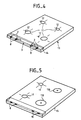
- the hob 13 includes a control panel equipped with 4 control mechanisms for power regulation 8 according to the present invention allowing the adjustment of flow rate and the ignition of the 4 burners 11.
- the burners are equipped with an automatic ignition device 12. It can be seen in FIG. 4, in addition to great safety and a remarkable ease of cleaning due to the partial sealing of the decorative strip 3 and the lack of roughness the cooktop in FIG. 4 has a very modern and very successful aesthetic.
- the hob 15 includes two gas burners 11 and two electric plates 110. It is understood that the use of other equipment such as for example 3 hobs 110 and / or 3 burners 11 does not depart from the scope of the present invention.
- the burners 11 are controlled by control mechanisms 8 according to the present invention as illustrated for example in FIGS. 1, 2 or 3. For aesthetic reasons it is advantageous to adjust the power of the electric plates 110 by the intermediate of a control mechanism 18 having the same external appearance as the mechanism 9. An example of such a mechanism is illustrated in FIG. 7.
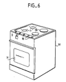
- FIG. 6 an exemplary embodiment of a stove 30 according to the present invention can be seen.
- the cooker 30 of FIG. 6 comprises two burners 11 and two electric plates 110. It is understood that the use of a cooker 30 comprising only gas burners 11 does not depart from the scope of the present invention.
- the stove 30 includes an oven 31.
- the oven 31 is for example an electric oven, in such a case it is controlled by a mechanism 18 similar to that controlling the electric plates 110. It is understood that for a gas oven one would use the mechanism 8 according to the present invention as 'illustrated in figure 2 or 3.
- FIG. 7 an exemplary embodiment of a control mechanism for regulating the power of an electric cooking appliance 18 can be seen.
- the mechanism 18 has the advantage of having an aesthetic similar to that of the appliance 8 in Figure 2. It is therefore particularly suitable for mixed gas-electric cooking appliances.
- the mechanism 18 of FIG. 7 comprises a power adjustment wheel 5 for example by rotating the axis of a rheostat 77.
- the wheel 5 is hidden at the top by a decorative strip 3. In the case of mechanisms 18 and therefore in the absence of the part 2 the decorative strip 3 does not have a recess.
- the wheel 5 is placed above the mechanical support for example of a hearth plate 6.
- the mechanism 18 has the same advantages as the mechanism 8 and in particular a pleasant aesthetic, a reduced risk of maneuvering by a child by the location of the accessible part of the wheel 5 and great ease of cleaning.
- a second mechanism 18 and for example a mechanism 8 has been placed.
- the present invention applies mainly to the regulation of the flow rate of a fluid such as for example to the control for the regulation of the power of a gas or mixed cooking appliance.
- the present invention mainly applies to the production of hobs or cookers.
Landscapes
- Engineering & Computer Science (AREA)
- Chemical & Material Sciences (AREA)
- Combustion & Propulsion (AREA)
- Mechanical Engineering (AREA)
- General Engineering & Computer Science (AREA)
- Feeding And Controlling Fuel (AREA)
- Baking, Grill, Roasting (AREA)
Claims (9)
- Steuermechanismus zur Leistungsregulierung einer Kochvorrichtung (30) mit einem Gashahn (7), enthaltend ein erstes Mittel (2), das es ermöglicht, den Gashahn zu entriegeln, sowie ein zweites Mittel (5), das es ermöglicht, die Öffnung des Gashahns durchzuführen, um die Regulierung der gewünschten Heizleistung zu bewirken, dadurch gekennzeichnet, daß das zweite Mittel (5), das es ermöglicht, die Öffnung des Gashahns zu bewirken, ein flaches Stell-Rändelrad ist, das zum großen Teil durch eine mit einem Ausschnitt (33) versehenen Schutzleiste (3) verdeckt ist, die die Handhabung des Rändelrads ermöglicht.
- Mechanismus nach Anspruch 1, dadurch gekennzeichnet, daß das Mittel (2), das die Entriegelung des Gashahns (7) ermöglicht, über die Schutzleiste (3) hervorragt.
- Mechanismus nach Anspruch 2, dadurch gekennzeichnet, daß das Mittel (2), das die Entriegelung des Gashahns (7) ermöglicht, von der Schutzleiste (3) über eine Aussparung der Leiste hervorragt.
- Mechanismus nach einem der Ansprüche 1 bis 3, dadurch gekennzeichnet, daß er eine automatische Zündvorrichtung (9, 10, 12) aufweist.
- Herdplatte (13, 15), dadurch gekennzeichnet, daß sie wenigstens einen Mechanismus (8) nach einem der Ansprüche 1 bis 4 aufweist.
- Kochvorrichtung (30), dadurch gekennzeichnet, daß sie wenigstens einen Mechanismus (8) nach einem der Ansprüche 1 bis 4 aufweist.
- Kochvorrichtung (30), dadurch gekennzeichnet, daß sie wenigstens einen durch einen Mechanismus (8) nach einem der Ansprüche 1 bis 4 gesteuerten Brenner (11) sowie wenigstens eine Elektroplatte (110) aufweist, die durch einen Mechanismus (18) gesteuert ist, der äußerlich mit dem den Brenner (11) steuernden Mechanismus (8) identisch ist.
- Kochvorrichtung (30) nach Anspruch 7, dadurch gekennzeichnet, daß die Steuervorrichtungen (8) der Brenner (11) und die Steuervorrichtungen (18) der der Elektroplatten (110) die gleiche Schutzleiste (3) besitzen.
- Kochvorrichtung (30) nach Anspruch 7 oder 8, dadurch gekennzeichnet, daß das Rändelrad (5) des Mechanismus (8) zur Regulierung der Heizleistung zwischen einer Herdplatte (6) und einem Trägerstück (4) der Schutzleiste (3) sitzt.
Applications Claiming Priority (2)
| Application Number | Priority Date | Filing Date | Title |
|---|---|---|---|
| FR8900378 | 1989-01-13 | ||
| FR8900378A FR2641852B1 (fr) | 1989-01-13 | 1989-01-13 | Mecanisme de commande pour regulation de puissance d'un appareil de cuisson et appareil de cuisson comportant un tel mecanisme |
Publications (2)
| Publication Number | Publication Date |
|---|---|
| EP0378460A1 EP0378460A1 (de) | 1990-07-18 |
| EP0378460B1 true EP0378460B1 (de) | 1993-07-28 |
Family
ID=9377701
Family Applications (1)
| Application Number | Title | Priority Date | Filing Date |
|---|---|---|---|
| EP19900400036 Expired - Lifetime EP0378460B1 (de) | 1989-01-13 | 1990-01-05 | Leistungsregler für Kochapparate und Kochapparat mit einem solchen Regler |
Country Status (4)
| Country | Link |
|---|---|
| EP (1) | EP0378460B1 (de) |
| DE (1) | DE69002333T2 (de) |
| ES (1) | ES2043295T3 (de) |
| FR (1) | FR2641852B1 (de) |
Families Citing this family (1)
| Publication number | Priority date | Publication date | Assignee | Title |
|---|---|---|---|---|
| IT1254227B (it) * | 1992-02-26 | 1995-09-14 | Smeg Spa | Dispositivo a leva per il comando dei rubinetti applicati ai piani di cottura ed alle cucine a gas |
Family Cites Families (5)
| Publication number | Priority date | Publication date | Assignee | Title |
|---|---|---|---|---|
| US1880648A (en) * | 1930-02-21 | 1932-10-04 | Yablick Max | Gas cock |
| DE706687C (de) * | 1939-06-15 | 1941-06-03 | Junkers & Co | Gashahn |
| US2187118A (en) * | 1939-10-24 | 1940-01-16 | John M V Ficklin | Valve latch |
| US3084681A (en) * | 1960-08-29 | 1963-04-09 | Roper Corp Geo D | Locking mechanism for burner control valves |
| DE2108269B1 (de) * | 1971-02-20 | 1972-06-08 | Joh. Vaülant KG, 5630 Remscheid | Drehgasschalter für Heizgeräte mit Zündsicherung |
-
1989
- 1989-01-13 FR FR8900378A patent/FR2641852B1/fr not_active Expired - Fee Related
-
1990
- 1990-01-05 DE DE1990602333 patent/DE69002333T2/de not_active Expired - Fee Related
- 1990-01-05 EP EP19900400036 patent/EP0378460B1/de not_active Expired - Lifetime
- 1990-01-05 ES ES90400036T patent/ES2043295T3/es not_active Expired - Lifetime
Also Published As
| Publication number | Publication date |
|---|---|
| EP0378460A1 (de) | 1990-07-18 |
| ES2043295T3 (es) | 1993-12-16 |
| FR2641852B1 (fr) | 1994-11-04 |
| DE69002333T2 (de) | 1993-11-18 |
| FR2641852A1 (fr) | 1990-07-20 |
| DE69002333D1 (de) | 1993-09-02 |
Similar Documents
| Publication | Publication Date | Title |
|---|---|---|
| EP0467901B1 (de) | Gaskochmulde | |
| US6029705A (en) | Gas control valve | |
| EP1563228B1 (de) | Heizung mit hohem wirkungsgrad | |
| CA2763681A1 (en) | Combination safety valve and ignition trigger for gas burners | |
| CN110486756A (zh) | 一种燃气炉 | |
| US6553986B1 (en) | Burner for a gas barbecue grill | |
| EP0378460A1 (de) | Leistungsregler für Kochapparate und Kochapparat mit einem solchen Regler | |
| EP0804707B1 (de) | Gasfeuerzeug mit sicherheitsvorrichtung | |
| FR2516277A3 (fr) | Bouton de commande et appareil menager comportant ce bouton | |
| JP5513204B2 (ja) | コンロ | |
| CN211232965U (zh) | 一种双模控制的燃气灶 | |
| AU2015213306A1 (en) | Wok table with turbo-charged burner | |
| FR2696612A1 (fr) | Table de cuisson. | |
| EP1446612A1 (de) | Feuerzeug mit windgeschützter flamme und feuersteinzünder | |
| FR2591720A1 (fr) | Commutateur rotatif pour cuisinieres a gaz | |
| JP2005043020A (ja) | ガスコンロ | |
| JPH0114803Y2 (de) | ||
| KR0148760B1 (ko) | 가스렌지의 노브 | |
| CN115751402B (zh) | 一种温控阀 | |
| FR2607579A1 (fr) | Four de cuisson a gaz, notamment pour usage menager | |
| EP1422475A1 (de) | Heizungsanlage mit Gasbrennern | |
| FR2623885A1 (fr) | Table de cuisson | |
| WO2003021152A1 (en) | A piezo ignition device | |
| FR2628176A1 (fr) | Robinet pour gaz equipe d'un systeme de securite a thermocouple, et appareil utilisant un tel robinet | |
| KR950005451Y1 (ko) | 휴대용 가스라이터 |
Legal Events
| Date | Code | Title | Description |
|---|---|---|---|
| PUAI | Public reference made under article 153(3) epc to a published international application that has entered the european phase |
Free format text: ORIGINAL CODE: 0009012 |
|
| AK | Designated contracting states |
Kind code of ref document: A1 Designated state(s): BE DE ES FR GB IT LU NL SE |
|
| 17P | Request for examination filed |
Effective date: 19900825 |
|
| 17Q | First examination report despatched |
Effective date: 19910417 |
|
| GRAA | (expected) grant |
Free format text: ORIGINAL CODE: 0009210 |
|
| AK | Designated contracting states |
Kind code of ref document: B1 Designated state(s): BE DE ES FR GB IT LU NL SE |
|
| ITF | It: translation for a ep patent filed | ||
| REF | Corresponds to: |
Ref document number: 69002333 Country of ref document: DE Date of ref document: 19930902 |
|
| GBT | Gb: translation of ep patent filed (gb section 77(6)(a)/1977) |
Effective date: 19931011 |
|
| REG | Reference to a national code |
Ref country code: ES Ref legal event code: FG2A Ref document number: 2043295 Country of ref document: ES Kind code of ref document: T3 |
|
| EPTA | Lu: last paid annual fee | ||
| PLBE | No opposition filed within time limit |
Free format text: ORIGINAL CODE: 0009261 |
|
| STAA | Information on the status of an ep patent application or granted ep patent |
Free format text: STATUS: NO OPPOSITION FILED WITHIN TIME LIMIT |
|
| 26N | No opposition filed | ||
| PGFP | Annual fee paid to national office [announced via postgrant information from national office to epo] |
Ref country code: SE Payment date: 19941219 Year of fee payment: 6 Ref country code: DE Payment date: 19941219 Year of fee payment: 6 |
|
| PGFP | Annual fee paid to national office [announced via postgrant information from national office to epo] |
Ref country code: LU Payment date: 19950101 Year of fee payment: 6 |
|
| PGFP | Annual fee paid to national office [announced via postgrant information from national office to epo] |
Ref country code: BE Payment date: 19950104 Year of fee payment: 6 |
|
| PGFP | Annual fee paid to national office [announced via postgrant information from national office to epo] |
Ref country code: ES Payment date: 19950119 Year of fee payment: 6 |
|
| EAL | Se: european patent in force in sweden |
Ref document number: 90400036.1 |
|
| PGFP | Annual fee paid to national office [announced via postgrant information from national office to epo] |
Ref country code: NL Payment date: 19950131 Year of fee payment: 6 |
|
| PGFP | Annual fee paid to national office [announced via postgrant information from national office to epo] |
Ref country code: GB Payment date: 19951220 Year of fee payment: 7 |
|
| PG25 | Lapsed in a contracting state [announced via postgrant information from national office to epo] |
Ref country code: LU Free format text: LAPSE BECAUSE OF NON-PAYMENT OF DUE FEES Effective date: 19960105 |
|
| PG25 | Lapsed in a contracting state [announced via postgrant information from national office to epo] |
Ref country code: SE Effective date: 19960106 Ref country code: ES Free format text: LAPSE BECAUSE OF NON-PAYMENT OF DUE FEES Effective date: 19960106 |
|
| PG25 | Lapsed in a contracting state [announced via postgrant information from national office to epo] |
Ref country code: BE Effective date: 19960131 |
|
| BERE | Be: lapsed |
Owner name: CIE EUROPEENNE POUR L'EQUIPEMENT MENAGER CEPEM Effective date: 19960131 |
|
| PG25 | Lapsed in a contracting state [announced via postgrant information from national office to epo] |
Ref country code: NL Effective date: 19960801 |
|
| NLV4 | Nl: lapsed or anulled due to non-payment of the annual fee |
Effective date: 19960801 |
|
| PG25 | Lapsed in a contracting state [announced via postgrant information from national office to epo] |
Ref country code: DE Effective date: 19961001 |
|
| EUG | Se: european patent has lapsed |
Ref document number: 90400036.1 |
|
| PG25 | Lapsed in a contracting state [announced via postgrant information from national office to epo] |
Ref country code: GB Effective date: 19970105 |
|
| GBPC | Gb: european patent ceased through non-payment of renewal fee |
Effective date: 19970105 |
|
| PGFP | Annual fee paid to national office [announced via postgrant information from national office to epo] |
Ref country code: FR Payment date: 19990126 Year of fee payment: 10 |
|
| PG25 | Lapsed in a contracting state [announced via postgrant information from national office to epo] |
Ref country code: FR Free format text: LAPSE BECAUSE OF NON-PAYMENT OF DUE FEES Effective date: 20000929 |
|
| REG | Reference to a national code |
Ref country code: FR Ref legal event code: ST |
|
| REG | Reference to a national code |
Ref country code: ES Ref legal event code: FD2A Effective date: 19970211 |
|
| PG25 | Lapsed in a contracting state [announced via postgrant information from national office to epo] |
Ref country code: IT Free format text: LAPSE BECAUSE OF NON-PAYMENT OF DUE FEES Effective date: 20050105 |