EP0378735A1 - Tauchkörpersystem für biologische Abwasserbehandlung - Google Patents
Tauchkörpersystem für biologische Abwasserbehandlung Download PDFInfo
- Publication number
- EP0378735A1 EP0378735A1 EP19890101024 EP89101024A EP0378735A1 EP 0378735 A1 EP0378735 A1 EP 0378735A1 EP 19890101024 EP19890101024 EP 19890101024 EP 89101024 A EP89101024 A EP 89101024A EP 0378735 A1 EP0378735 A1 EP 0378735A1
- Authority
- EP
- European Patent Office
- Prior art keywords
- chamber
- fluid
- chambers
- extending
- vessel
- Prior art date
- Legal status (The legal status is an assumption and is not a legal conclusion. Google has not performed a legal analysis and makes no representation as to the accuracy of the status listed.)
- Granted
Links
- 238000004065 wastewater treatment Methods 0.000 title abstract 2
- 239000007789 gas Substances 0.000 claims abstract description 77
- 239000012530 fluid Substances 0.000 claims abstract description 66
- 238000012856 packing Methods 0.000 claims abstract description 47
- 238000000034 method Methods 0.000 claims abstract description 31
- 230000008569 process Effects 0.000 claims abstract description 28
- 239000007788 liquid Substances 0.000 claims abstract description 26
- 239000000126 substance Substances 0.000 claims abstract description 17
- 238000004891 communication Methods 0.000 claims abstract description 13
- 239000011159 matrix material Substances 0.000 claims description 31
- QVGXLLKOCUKJST-UHFFFAOYSA-N atomic oxygen Chemical compound [O] QVGXLLKOCUKJST-UHFFFAOYSA-N 0.000 claims description 23
- 239000001301 oxygen Substances 0.000 claims description 23
- 229910052760 oxygen Inorganic materials 0.000 claims description 23
- 239000002699 waste material Substances 0.000 claims description 20
- XLYOFNOQVPJJNP-UHFFFAOYSA-N water Substances O XLYOFNOQVPJJNP-UHFFFAOYSA-N 0.000 claims description 18
- 239000000463 material Substances 0.000 claims description 14
- 244000005700 microbiome Species 0.000 claims description 14
- 238000005086 pumping Methods 0.000 claims description 14
- 238000012546 transfer Methods 0.000 claims description 10
- 230000015556 catabolic process Effects 0.000 claims description 6
- 238000006731 degradation reaction Methods 0.000 claims description 6
- 230000006872 improvement Effects 0.000 claims description 5
- 239000010815 organic waste Substances 0.000 claims description 5
- 230000029087 digestion Effects 0.000 claims description 4
- 230000006698 induction Effects 0.000 claims description 4
- 238000004090 dissolution Methods 0.000 claims description 3
- 238000012423 maintenance Methods 0.000 claims description 3
- 238000007872 degassing Methods 0.000 claims 2
- 241001148471 unidentified anaerobic bacterium Species 0.000 claims 2
- UCKMPCXJQFINFW-UHFFFAOYSA-N Sulphide Chemical compound [S-2] UCKMPCXJQFINFW-UHFFFAOYSA-N 0.000 claims 1
- 241001148470 aerobic bacillus Species 0.000 claims 1
- 230000002708 enhancing effect Effects 0.000 claims 1
- 229910052751 metal Inorganic materials 0.000 claims 1
- 239000002184 metal Substances 0.000 claims 1
- 150000002739 metals Chemical class 0.000 claims 1
- DOTMOQHOJINYBL-UHFFFAOYSA-N molecular nitrogen;molecular oxygen Chemical compound N#N.O=O DOTMOQHOJINYBL-UHFFFAOYSA-N 0.000 claims 1
- 150000002823 nitrates Chemical class 0.000 claims 1
- 239000002244 precipitate Substances 0.000 claims 1
- 150000003467 sulfuric acid derivatives Chemical class 0.000 claims 1
- 230000032258 transport Effects 0.000 claims 1
- 239000002351 wastewater Substances 0.000 abstract description 14
- 238000013019 agitation Methods 0.000 abstract 1
- 239000000203 mixture Substances 0.000 description 7
- 239000007787 solid Substances 0.000 description 7
- 239000006185 dispersion Substances 0.000 description 6
- VNWKTOKETHGBQD-UHFFFAOYSA-N methane Chemical compound C VNWKTOKETHGBQD-UHFFFAOYSA-N 0.000 description 6
- 238000005273 aeration Methods 0.000 description 5
- 241000894006 Bacteria Species 0.000 description 4
- CURLTUGMZLYLDI-UHFFFAOYSA-N Carbon dioxide Chemical compound O=C=O CURLTUGMZLYLDI-UHFFFAOYSA-N 0.000 description 4
- 238000012545 processing Methods 0.000 description 4
- IJGRMHOSHXDMSA-UHFFFAOYSA-N Atomic nitrogen Chemical compound N#N IJGRMHOSHXDMSA-UHFFFAOYSA-N 0.000 description 3
- OKKJLVBELUTLKV-UHFFFAOYSA-N Methanol Chemical compound OC OKKJLVBELUTLKV-UHFFFAOYSA-N 0.000 description 3
- 238000005276 aerator Methods 0.000 description 3
- 229910002651 NO3 Inorganic materials 0.000 description 2
- NHNBFGGVMKEFGY-UHFFFAOYSA-N Nitrate Chemical compound [O-][N+]([O-])=O NHNBFGGVMKEFGY-UHFFFAOYSA-N 0.000 description 2
- 230000031018 biological processes and functions Effects 0.000 description 2
- 229910002092 carbon dioxide Inorganic materials 0.000 description 2
- 239000001569 carbon dioxide Substances 0.000 description 2
- 238000006243 chemical reaction Methods 0.000 description 2
- 230000000694 effects Effects 0.000 description 2
- 235000013305 food Nutrition 0.000 description 2
- 239000011261 inert gas Substances 0.000 description 2
- 230000003647 oxidation Effects 0.000 description 2
- 238000007254 oxidation reaction Methods 0.000 description 2
- 230000001706 oxygenating effect Effects 0.000 description 2
- 239000002245 particle Substances 0.000 description 2
- 229920000915 polyvinyl chloride Polymers 0.000 description 2
- 239000004800 polyvinyl chloride Substances 0.000 description 2
- 230000000630 rising effect Effects 0.000 description 2
- 238000010408 sweeping Methods 0.000 description 2
- 239000003643 water by type Substances 0.000 description 2
- 239000002028 Biomass Substances 0.000 description 1
- 229920000114 Corrugated plastic Polymers 0.000 description 1
- RWSOTUBLDIXVET-UHFFFAOYSA-N Dihydrogen sulfide Chemical compound S RWSOTUBLDIXVET-UHFFFAOYSA-N 0.000 description 1
- MYMOFIZGZYHOMD-UHFFFAOYSA-N Dioxygen Chemical compound O=O MYMOFIZGZYHOMD-UHFFFAOYSA-N 0.000 description 1
- 241000446313 Lamella Species 0.000 description 1
- 239000004743 Polypropylene Substances 0.000 description 1
- NINIDFKCEFEMDL-UHFFFAOYSA-N Sulfur Chemical compound [S] NINIDFKCEFEMDL-UHFFFAOYSA-N 0.000 description 1
- 240000008042 Zea mays Species 0.000 description 1
- 235000005824 Zea mays ssp. parviglumis Nutrition 0.000 description 1
- 235000002017 Zea mays subsp mays Nutrition 0.000 description 1
- 238000009825 accumulation Methods 0.000 description 1
- 239000002253 acid Substances 0.000 description 1
- WYTGDNHDOZPMIW-RCBQFDQVSA-N alstonine Natural products C1=CC2=C3C=CC=CC3=NC2=C2N1C[C@H]1[C@H](C)OC=C(C(=O)OC)[C@H]1C2 WYTGDNHDOZPMIW-RCBQFDQVSA-N 0.000 description 1
- 238000004140 cleaning Methods 0.000 description 1
- 230000002301 combined effect Effects 0.000 description 1
- 235000005822 corn Nutrition 0.000 description 1
- 230000003247 decreasing effect Effects 0.000 description 1
- 238000013461 design Methods 0.000 description 1
- 238000010586 diagram Methods 0.000 description 1
- 238000009792 diffusion process Methods 0.000 description 1
- 238000006073 displacement reaction Methods 0.000 description 1
- 238000005265 energy consumption Methods 0.000 description 1
- 239000000446 fuel Substances 0.000 description 1
- 239000000383 hazardous chemical Substances 0.000 description 1
- 239000001257 hydrogen Substances 0.000 description 1
- 229910052739 hydrogen Inorganic materials 0.000 description 1
- 125000004435 hydrogen atom Chemical class [H]* 0.000 description 1
- 229910000037 hydrogen sulfide Inorganic materials 0.000 description 1
- 239000010808 liquid waste Substances 0.000 description 1
- 230000007246 mechanism Effects 0.000 description 1
- 229910052757 nitrogen Inorganic materials 0.000 description 1
- JCXJVPUVTGWSNB-UHFFFAOYSA-N nitrogen dioxide Inorganic materials O=[N]=O JCXJVPUVTGWSNB-UHFFFAOYSA-N 0.000 description 1
- 230000033116 oxidation-reduction process Effects 0.000 description 1
- 230000037361 pathway Effects 0.000 description 1
- 239000002985 plastic film Substances 0.000 description 1
- -1 polypropylene Polymers 0.000 description 1
- 229920001155 polypropylene Polymers 0.000 description 1
- 230000003134 recirculating effect Effects 0.000 description 1
- 230000009467 reduction Effects 0.000 description 1
- 238000005201 scrubbing Methods 0.000 description 1
- 239000010802 sludge Substances 0.000 description 1
- 230000003068 static effect Effects 0.000 description 1
- 229910052717 sulfur Inorganic materials 0.000 description 1
- 239000011593 sulfur Substances 0.000 description 1
- 239000006188 syrup Substances 0.000 description 1
- 235000020357 syrup Nutrition 0.000 description 1
- 230000007306 turnover Effects 0.000 description 1
Images

Classifications
-
- C—CHEMISTRY; METALLURGY
- C02—TREATMENT OF WATER, WASTE WATER, SEWAGE, OR SLUDGE
- C02F—TREATMENT OF WATER, WASTE WATER, SEWAGE, OR SLUDGE
- C02F3/00—Biological treatment of water, waste water, or sewage
- C02F3/02—Aerobic processes
- C02F3/06—Aerobic processes using submerged filters
-
- C—CHEMISTRY; METALLURGY
- C02—TREATMENT OF WATER, WASTE WATER, SEWAGE, OR SLUDGE
- C02F—TREATMENT OF WATER, WASTE WATER, SEWAGE, OR SLUDGE
- C02F3/00—Biological treatment of water, waste water, or sewage
- C02F3/02—Aerobic processes
- C02F3/10—Packings; Fillings; Grids
- C02F3/101—Arranged-type packing, e.g. stacks, arrays
-
- C—CHEMISTRY; METALLURGY
- C02—TREATMENT OF WATER, WASTE WATER, SEWAGE, OR SLUDGE
- C02F—TREATMENT OF WATER, WASTE WATER, SEWAGE, OR SLUDGE
- C02F3/00—Biological treatment of water, waste water, or sewage
- C02F3/28—Anaerobic digestion processes
- C02F3/2806—Anaerobic processes using solid supports for microorganisms
-
- Y—GENERAL TAGGING OF NEW TECHNOLOGICAL DEVELOPMENTS; GENERAL TAGGING OF CROSS-SECTIONAL TECHNOLOGIES SPANNING OVER SEVERAL SECTIONS OF THE IPC; TECHNICAL SUBJECTS COVERED BY FORMER USPC CROSS-REFERENCE ART COLLECTIONS [XRACs] AND DIGESTS
- Y02—TECHNOLOGIES OR APPLICATIONS FOR MITIGATION OR ADAPTATION AGAINST CLIMATE CHANGE
- Y02W—CLIMATE CHANGE MITIGATION TECHNOLOGIES RELATED TO WASTEWATER TREATMENT OR WASTE MANAGEMENT
- Y02W10/00—Technologies for wastewater treatment
- Y02W10/10—Biological treatment of water, waste water, or sewage
Definitions
- This invention relates to a process and reactor suitable for biological treatment of wastewater or for other applications involving intimate contact between biological populations attached to a fixed surface.
- fixed film refers to systems where the microorganisms are attached to the surface of a solid inert material as opposed to being freely suspended as e.g., agglomerated particles in a liquid medium.
- a submerged system in which the fixed film is submerged in a aqueous liquor
- a trickle-bed system which the fixed film is exposed to the atmosphere in aqueous liquors trickled over the film
- a combination in which the fixed film is alternately immersed in an aqueous liquor, and then exposed to air or inert gas as is done in a rotating biological contacter.
- the micro organisms are attached either to the surface of the immobile solid matrices or to mobile solid particles submerged in a aqueous liquor.
- U.S. Patent No. 3,966,608 illustrates a submerged technique for aerobically biologically treating waste products containing submerged packing, such as Raschig or Pall rings.
- the treatment zone utilizes a central column and adjacent oxidation zones in fluid communication with the central column.
- An aerating fan is located at the top of column to draw the liquor upwardly through the column and the waste sprayed outwardly over a packing to effect aeration thereof, and then caused to flow downwardly through the adjacent columns.
- the microorganisms which are fixed to the packing effect oxidation of the waste.
- U.S. Patent No. 3,235,234 illustrates a technique for treating waste, wherein a treatment zone is immersed in tank containing waste, the treatment zone being filled with a porous packing such as saddles, wire mesh or corrugated sheets defining a serpentine path in the vertical direction.
- An oxygenating gas is introduced through a diffuser, such as a sparge unit, placed beneath the packing. Both waste and oxygenating gas are forced upwardly through the packing unit and the waste biologically digested.
- U.S. Patent No. 4,267,052 discloses a process an apparatus for aerating and circulating a liquid in a vessel utilizing a surface aerator and bottom mixing rotor mounted on a hollow common shaft. The combination of the surface aerator and submerged rotor permits good bottom mixing as well as aeration of the medium at the bottom of the tank for enhanced biological degradation.
- U.S. Patent No. 4,425,231 discloses a wastewater treating apparatus which includes a circulation type aeration tank, having both downward and upward flow chambers which communicate with each other at the upward and lower ends. An oxygenated gas is supplied to the downward flow chamber and wastewater and return sludge are applied to a given position or elevation in the upward flow chamber such that a reduction zone with low concentration of dissolved oxygen is formed at the upper portion of the upper flow chamber.
- This invention relates to an improvement in a submerged fixed film biological treatment system and in a reactor for use in such system.
- the improvement in the biological fixed film system involves establishing a housing having at least one independent-vertical chamber each open at the top and bottom and each chamber being in fluid communication with the other at both top and bottom, and filled with high surface-area packing, which defines a serpentine pathway in the vertical direction.
- the independent-vertical chamber is disposed annularly around a central-vertical chamber which is also open at the top and bottom.
- the top and bottom of the central chamber is in fluid communication with the top and bottom of each of the annular independent-vertical chambers.
- At the top of the central-vertical chamber and top of independent-vertical chamber there is a top-freeboard chamber created by setting the liquid level in the reactor at a position above the top of all vertical chambers.
- the central chamber is free of packing, but contains a pumping means for generating downward flow of fluid and gases in said central-vertical chamber.
- the gas and fluid mixture move downward through the central-chamber and upon reaching the floor of the reactor it is radially dispersed across the floor of the reactor which extends below the chambers sweeping it clean of solids.
- the mixture then flows vertically upward through the independent-vertical chambers.
- the gas disengages and the fluid flows radially inward in the top-freeboard chamber and returns to the central-vertical chamber pump for recirculation.
- the reactor thus provides a continuous toroidal recirculation of fluid and/or fluid and gases within the reactor housing.
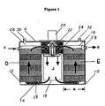
- FIG. 1 A sealed housing 4 having an inlet 6 for introduction of wastewater or water borne chemicals, an effluent line 8 for removal of biologically treated effluent.
- a drain 10 is located near the bottom of housing 4, and may be used for periodically cleaning exceptionally heavy grit from the housing.
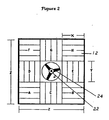
- a plurality of vertically extending chambers A and B (identified as chambers A, B, C, D, E, F, G, and H in Figure 2, are disposed about a central chamber J.
- the chambers A-H are arranged such that they form a ring around chamber J, with each chamber being in fluid communications at the top and at the bottom with central chamber J and with every other chamber.
- Within chambers A-H are contained corrugated packing or other high surface-area packing materials 12 supported on a structural grid 14.
- Each vertically extending chamber designated A-H and including J is separate and independent from the others at all points except at the bottom and top of the column so that there is no fluid flow in a horizontal direction between the chambers. This prevents horizontal short circuiting and encourages uniform upward vertical fluid and gas flow through the packing.
- the annular independent-vertical chambers A-H should also be of equivalent size to encourage equal distribution of upward vertical flow through the plurality of chambers. Many configurations are possible e.g. rectangular or combined as a single chamber or unit. An example of a rectangular system would be a combination of chambers F, G and H and A, C, and D. For efficient arrangement the chambers defining the annular ring are square and there are eight in number.
- Central chamber J also is equal in size to the chambers A-H.
- Waste influent is added to the reactor to a waste level 16 filling all of the chambers.
- a top freeboard 26 establishes a gaseous area within the housing which serves as a source of gas if aerobic conditions are required or inert gas source if anaerobic conditions are required.
- the packing used in the annular independent-vertical chambers A-H which is thusly immersed in wastewater may be of the rigid matrix type or may be random packing materials, e.g., Raschig rings, pall rings etc.
- Matrix blocks are preferred and usually are formed from thin sheets of corrugated polyvinyl chloride or polypropylene. The individual diagonally-corrugated sheets are typically glued in stacks with flutes on alternate sheets at opposing angles and oriented 30° to the direction of the flow of gases and liquid through the matrix module.
- the matrix blocks should have surface to volume ratios varying from 20-70 square feet per cubic foot and behave as static mixers and gas dispersion devices, as well as providing biological growth surface, when they are employed in the manner of this invention.
- the matrix blocks are typical from one to two feet high, from one to two feet wide and from one to twelve feet long.
- each layer is angularly offset from the layer above or below it usually by 90° which is the most efficient angular offset.
- the offset angle could range typically from 45-90° however depending on the particular matrix block configuration.
- the preferred matrix block orientation provides more effective dispersion of gas and liquid as it moves rapidly upward through the stack of matrix blocks in each annular independent-vertical chamber.
- Each of the annular independent-vertical chambers A-H should be packed identically so that the resistance to fluid flow in each will be the same. The waste fluid received by chambers A-H from the central chamber J will thus be more uniformly distributed to each of the vertically extending annular chambers A-H.
- each independent-vertical chamber A-H By alternating the orientation of the first layer of blocks in each independent-vertical chamber A-H as shown in Figure 2 the matrix blocks in each layer of a given annular independent vertical chamber interact with those in the adjacent vertical chamber to create an impervious vertical wall between all vertical chambers A-H.
- Perforations are sometimes introduced into the individual corrugated plastic sheets making up commercially available matrix blocks. This is to improve distribution and mixing between the gas and liquid flowing through the matrix blocks.
- the lamellas in the preferred matrix module, for use in the fixed film biological system of this invention, have no perforations in order to prevent horizontal flow between chambers A-H.
- Draft tube 18 which is fitted to the square opening of chamber J by square-horizontal baffles fitted to the top and bottom of the open ended, top and bottom, draft tube 18.
- This tube 18 also serves as a housing for an axial flow downward pumping system comprising motor 20, shaft 22 and impeller 20.
- the effectiveness of the pumping system and as an aerator is greatly enhanced by draft tube 18 in chamber J although the system can be operated without the draft tube.
- the axial flow pump may be designed to induce air flow down shaft 22, e.g., via a concentric hollow shaft. The gases are introduced to the fluid below impeller 24 and the gases thus induced are finely dispersed as bubbles into the liquid and entrained therein.
- the pumping capacity of the pump-impeller 24, and the size of the draft tube 18 in which the pump operates establishes the downward vertical velocity for carrying the bubbles to the floor of the reactor.
- the preferred downward velocity is 2.5 to 3.5 feet per second but the system can be operated between 1.5 and 4.0 feet per second or more. It is also well known that the larger the impeller diameter relative to the effective diameter of the tank the more rapidly the tank can be mixed at a given horsepower.
- the ratio of impeller diameter (d imp ) to effective tank diameter (d tank ) is 0.25 and preferably between 0.10 to 0.29. This minimizes energy consumption per treatment capacity.
- the overall pumping capacity of the pumping device e.g., an axial flow pump required in the central-vertical chamber is also a function of the desired upward vertical velocity through the packing in the annular independent-vertical chambers A-H.
- the preferred velocity upward through the packing is 0.22 to 0.32 but can range from 0.13 to 0.36 feet/second.
- the downward velocity in central chamber J and upward velocity in chambers A-H important, but the horizontal velocity of fluid and gas mixtures sweeping the floor of the vessel is also important.
- the velocity of the liquid must accelerate to velocities that will carry the gas bubbles nearly to the outer edges of the annular and independent vertical chambers A-H.
- the bubbles frequently encounter mixing and dispersion points in the matrix blocks or packing material and are broken into smaller bubbles or prevented from coalescing.
- the relatively slow progression of the bubbles through the packing, the continual dispersion of the gas bubbles as they rise through the packing, and the relatively turbulent flow created within the packing by the specified upward fluid flow velocities in the packing combine a second aeration means.
- the combined gas dissolution efficiency of the two aeration means provides for enhanced treatment capacity. Both gas transfer processes are powered by the same motive force and thus the efficiency of the reactor is high.
- the internal mixing patterns of the submerged film biological system of this invention are as follows. Influent from inlet 6 first mixes with liquid rising up through the packing 12 and flows to the center chamber J where it is mixed with fluid contained in the fixed film biological system. The mixture is pumped to the bottom of the reactor housing 4 with or without entrained gases where the high horizontal velocity fluid sweeps the floor clear of solids and the fluid and gases, if present, then rise through the packing in the independent vertical chambers to the waters surface where entrained gases may be released to the top freeboard chamber 26 above the water. The fluid then below top freeboard chamber 26 entrains new influent waters, flows radially inward to central chamber J and repeats the flow pattern.
- the overall pattern of mixing in the fixed film biological system of this invention is that of a torus.
- the toroidal flow pattern of this invention results in a completely mixed submerged film biological system.
- the latter is unique in that most other fixed film biological reactor sytems have strong plug flow characteristics and thus a decreasing concentration gradient as the waste proceeds through the unit. The latter is due to the use of two dimensional mixing patters or a lack of provision for proper and sufficient turnover of fluid in the reactor.
- the appartus is uniquely versatile and can be operated in an anaerobic mode, a facultatively anaerobic mode or in an aerobic biological treatment mode depending on the nature of the wastewater or water-borne chemicals to be treated.
- This versatility is exercised by controlling the composition of the gases in top freeboard chamber 26 of the submerged film biological system.
- a dissolved oxygen free environment i.e., an anaerobic environment
- the top-freeboard chamber 26 of the reactor is isolated from the atmosphere by closing off air inlet 30, and is thus starved of gaseous oxygen.
- the bacteria consume any oxygen present in the gaseous freeboard space, the incoming influent and the fluid within the sealed housing 4.
- the Oxidation Reduction Potential (ORP) of the process drops to -470 ⁇ 30 mv. and the bacteria begin to operate anaerobically.
- Methane which may be produced under these conditions is vented from sealed housing 4 through vent 32 and a water trap (not shown) to prevent entrance of oxygen.
- the methane may be used as fuel or flared.
- the pumping device in central chamber J may or may not be operated in a gas induction mode.
- gas recirculation is not required for anaerobic operation it may be desirable in cases for example where hydrogen sulfide can be scrubbed from the gases into freeboard chamber 26 using a separate scrubbing tower in a side loop process, to reduce the sulfur content of the wastewater being treated.
- the top freeboard 26 of the fixed film biological reactor may be purged with air or pure oxygen at controlled rates and the pumping device in central chamber J used to induce a large flow of oxygen-rich gases into the down-flowing fluid in the central chamber J.
- the combined effects of the gas induction with high shear and high fluid velocities, toroidal dispersion of liquid and gases, maintenance of high liquid velocities through the packing and across the reactor floor, and gassing of the entire high surface-area packing provides unusually high oxygen-dissolution efficiency, reactor efficiency and reactor capacity in this invention.
- Figure 3 is a schematic of a process train of submerged film biological reactors of this invention and illustrates a six stage treatment process, comprising anaerobic, aerobic and facultative anaerobic (anoxic) treatment of water or water borne chemicals. More specifically, the waste treatment system comprises Sections 50, 70 and 90, each section having two stages, with each stage designed in accordance with the embodiment described in Figure 1. Each stage has an inlet 52, 72, and 92, the inlet 72 constituting the outlet from section 50 and the inlet 92 constituting the outlet from section 70.
- Each stage has vertical extending chambers A-H filled with high surface-area rigid polyvinyl chloride matrix blocks for support of the microorganisms and enhanced gas transfer to and from the fluid, placed in the preferred layered orientation for good fluid distribution between the chambers, as shown in Figure 2.
- waste is taken from an aerated lagoon 40, through line 42 to influent pump 44, for introduction into stage 1 of section 50. This is pumped through line 52 into stage 1 which in conjunction with stage 2 is operated under anaerobic conditions.
- Stage 1 and stage two are in fluid communication through the top and bottom freeboard cross sectional areas or through restricted opening at the top freeboard water level.
- Air is prohibited from entering the gaseous freeboard above the matrix blocks of section 50 and anaerobic microorganism growth is facilitated by virtue of the effective contacting of the oxygen free fluids of the reactor with the biomass fixed to the high surface-area matrix contained therein.
- the toroidal mixing pattern embodied in this invention is maintained in the reactors with the fluid flowing downward in chamber J and then rising through the independent-vertical chamber A-H. Uniformity of flow and maintenance of toroidal flow patterns lead to enhanced digestion rates.
- section 70 comprises two stages, i.e., stages 3 and 4 each stage embodying elements as described in Figure 1.
- section 70 is operated under aerobic conditions by introducing fresh air under very low pressure; e.g. between 1" to 10" of water column, into the gaseous freeboard of section 70 at a rate such that the oxygen content of the gas in the top freeboard chamber does not become significantly depleted of oxygen.
- the gases in the top freeboard chamber, including oxygen are induced into the axial flow pump in chamber J of both stage 3 and 4.
- the transfer of oxygen to the recirculating fluid from the gas bubbles thus entrained in the draft tube and matrix block packing of chambers A-H permits the bacteria to complete aerobic degradation of residual chemicals in the effluent of section 50, at a high rate.
- the final section, 90 embodies a two stage system, i.e., stage 5 and stage 6, with stage 5 operating anoxically (nitrate is used by the microorganisms as a source of oxygen and no elemental dissolved oxygen or gaseous oxygen is available in stage 5) and stage 6 operating aerobically.
- stage 5 operating anoxically (nitrate is used by the microorganisms as a source of oxygen and no elemental dissolved oxygen or gaseous oxygen is available in stage 5) and stage 6 operating aerobically.
- the top freeboard chambers of stage 5 and stage 6 are necessarily separate in section 90 as opposed to section 50 and 70 wherein they communicate through restricted openings or over the entire cross section of the top freeboard chamber.
- the effluent from section 70 is introduced to section 90 through line 92 and anoxic conditions are maintained in stage 5 by excluding oxygen from the top freeboard chamber of stage 5.
- a water-trap vent 54 is required on stage 5 to vent gaseous nitrogen and carbon dioxide from stage 5 of section 90.
- a secondary source of food is introduced to stage 5 when necessary.
- the secondary source of food may be methanol, corn syrup or other readily degradable non hazardous chemicals. In some cases a slip of stream of raw influent wastewater may be used. As shown this is piped through line 46 to pump 48 then line 50 to stage 5.
- Treated fluid flows from stage 5 to stage 6 through a flooded gas seal wire which minimizes back mixing of gases and liquid between the anoxic stage 5 and aerobic stage 6.
- aerobic treatment similar to that described for stages 3 and 4 is accomplished to complete the sequential biological treatment process.
- Air is again introduced to the top freeboard chamber of stage 6 at a low pressure and at controlled rates to achieve desired aerobic treatment conditions.
- Spent air is discharged through vent 56 to the atmosphere.
- Effluent from stage 6 is withdrawn through line 58 and discharged into a clarifier 66 wherein biological solids are removed.
- the clean treated water can then be discharged to the sewer through line 68 or to a clean receiving stream.
Landscapes
- Life Sciences & Earth Sciences (AREA)
- Microbiology (AREA)
- Biodiversity & Conservation Biology (AREA)
- Hydrology & Water Resources (AREA)
- Engineering & Computer Science (AREA)
- Environmental & Geological Engineering (AREA)
- Water Supply & Treatment (AREA)
- Chemical & Material Sciences (AREA)
- Organic Chemistry (AREA)
- Biological Treatment Of Waste Water (AREA)
Priority Applications (1)
| Application Number | Priority Date | Filing Date | Title |
|---|---|---|---|
| DE68914432T DE68914432T2 (de) | 1989-01-20 | 1989-01-20 | Tauchkörpersystem für biologische Abwasserbehandlung. |
Applications Claiming Priority (1)
| Application Number | Priority Date | Filing Date | Title |
|---|---|---|---|
| US07/070,899 US4818404A (en) | 1987-07-08 | 1987-07-08 | Submerged biological wastewater treatment system |
Publications (2)
| Publication Number | Publication Date |
|---|---|
| EP0378735A1 true EP0378735A1 (de) | 1990-07-25 |
| EP0378735B1 EP0378735B1 (de) | 1994-04-06 |
Family
ID=22098039
Family Applications (1)
| Application Number | Title | Priority Date | Filing Date |
|---|---|---|---|
| EP19890101024 Expired - Lifetime EP0378735B1 (de) | 1987-07-08 | 1989-01-20 | Tauchkörpersystem für biologische Abwasserbehandlung |
Country Status (2)
| Country | Link |
|---|---|
| US (1) | US4818404A (de) |
| EP (1) | EP0378735B1 (de) |
Cited By (3)
| Publication number | Priority date | Publication date | Assignee | Title |
|---|---|---|---|---|
| EP0539624A1 (de) * | 1991-10-24 | 1993-05-05 | NET Co., Ltd. | Träger gebraucht in einer Vorrichtung für die Aufbereitung von organischem Abwasser |
| EP0569828A1 (de) * | 1992-05-14 | 1993-11-18 | Herold & Co. GmbH | Anaerobe Aufbereitungsanlage für Abwässer, Fäkalien und Gülle |
| WO2010006320A3 (en) * | 2008-07-11 | 2010-04-08 | Richard Aho | Biological processing for beneficial use |
Families Citing this family (38)
| Publication number | Priority date | Publication date | Assignee | Title |
|---|---|---|---|---|
| DE3738295A1 (de) * | 1987-09-03 | 1989-03-16 | Tecon Gmbh | Reaktor und verfahren zum biologischen reinigen von schadstoffhaltigem wasser |
| GB9009205D0 (en) * | 1990-04-24 | 1990-06-20 | Mcdonald Alistair J | Process and apparatus for biological treatment of effluent |
| US5096596B1 (en) * | 1990-06-27 | 1995-10-03 | Hellenbrand Water Conditioners | Process and apparatus fof removal of mineral contaminants from water |
| JP3127233B2 (ja) * | 1991-04-01 | 2001-01-22 | 彊 有水 | 固定生物膜濾材及びこれを使用した汎用汚水処理装置 |
| EP0517649B1 (de) * | 1991-06-07 | 1996-03-27 | Sulzer Chemtech AG | Festbettreaktor zum biologischen Abwasserreinigen |
| US5298164A (en) * | 1992-07-28 | 1994-03-29 | United States Filter Corporation | Emission reduction of organic volatiles from aerobic biological reactors |
| US5316668A (en) * | 1992-12-22 | 1994-05-31 | Jet, Inc. | Wastewater treatment plant and apparatus |
| US5484524A (en) * | 1993-02-01 | 1996-01-16 | Jet, Inc. | Wastewater treatment apparatus |
| DE4321552C1 (de) * | 1993-06-29 | 1994-10-20 | Peter Prof Dr Kunz | Vorrichtung und Verfahren zur kontinuierlichen biologischen Abwasserreinigung - insbesondere für kleinere und mittlere Industriebetriebe |
| US5454949A (en) * | 1994-01-03 | 1995-10-03 | Davis; Harold E. | Sewage treatment system and method |
| US5674399A (en) * | 1995-06-05 | 1997-10-07 | Davis; Harold E. | Sewage treatment method |
| US5733454A (en) * | 1996-04-26 | 1998-03-31 | Ehh Holding Co., Inc. | Process and apparatus for the treatment of flowable waste |
| US5772887A (en) * | 1997-03-28 | 1998-06-30 | Lockheed Martin Idaho Technologies Company | Modular bioreactor for the remediation of liquid streams and methods for using the same |
| US6436288B1 (en) | 1999-02-08 | 2002-08-20 | Mississippi State University | Bast medium biological reactor treatment system for remediation and odor suppression of organic waste streams |
| RU2180895C2 (ru) * | 2000-06-05 | 2002-03-27 | Степкин Андрей Андреевич | Способ биологической очистки сточных вод |
| US6383370B1 (en) | 2000-09-14 | 2002-05-07 | Infilco Degremont Inc. | Apparatus for treating wastewater |
| US20030150817A1 (en) * | 2002-02-11 | 2003-08-14 | Keever Christopher S. | Method and apparatus for treating wastewater |
| US7297274B2 (en) * | 2001-10-24 | 2007-11-20 | University Of Florida Research Foundation, Inc. | Fixed-film anaerobic digestion of flushed waste |
| US7326340B2 (en) * | 2003-03-05 | 2008-02-05 | Siemens Water Technologies Holding Corp. | System for controlling sulfide generation |
| US7087172B2 (en) * | 2003-03-05 | 2006-08-08 | Usfilter Corporation | Methods for reducing nitrate demands in the reduction of dissolved and/or atmospheric sulfides in wastewater |
| US7008539B2 (en) * | 2003-05-14 | 2006-03-07 | University Of Utah Research Foundation | Submerged ammonia removal system and method |
| US6986850B2 (en) * | 2003-07-07 | 2006-01-17 | Micron Technology, Inc. | Partial edge bead removal to allow improved grounding during e-beam mask writing |
| US7285217B2 (en) * | 2003-12-02 | 2007-10-23 | Siemens Water Technologies Corp. | Removing odoriferous sulfides from wastewater |
| US20070241062A9 (en) * | 2004-07-08 | 2007-10-18 | Simpson Gregory D | Synergistic composition and method for odor control |
| WO2006058097A1 (en) * | 2004-11-22 | 2006-06-01 | Entex Technologies Inc. | System for treating wastewater and a controlled reaction-volume module usable therein |
| FR2884442B1 (fr) * | 2005-04-19 | 2007-05-25 | Air Liquide | Dispositif d'agitation d'un liquide et d'injection d'un gaz dans ce liquide adapte a des bassins de faibles profondeurs |
| US7465394B2 (en) * | 2006-09-05 | 2008-12-16 | Aeration Industries International, Inc. | Wastewater treatment system |
| USD672009S1 (en) | 2009-11-02 | 2012-12-04 | Entex Technologies Inc. | Extruded media for supporting growth biology within a wastewater treating system |
| US7799224B2 (en) * | 2008-01-30 | 2010-09-21 | Siemens Water Technologies Corp. | Wastewater treatment methods |
| CN102317215A (zh) | 2008-12-22 | 2012-01-11 | 犹他州立大学研究基金会 | 用于从水性介质中去除不想要的物质的水下系统及方法 |
| DE102009017067A1 (de) * | 2009-04-09 | 2010-10-14 | Fuchs, Leonhard, Dipl.-Ing. | Anlage zur biologischen Abwasserbehandlung |
| US8568593B1 (en) | 2009-06-02 | 2013-10-29 | Entex Technologies, Inc. | Anoxic system screen scour |
| US8066879B2 (en) * | 2009-06-17 | 2011-11-29 | Absolute Aeration | Method for treating waste water |
| CA2773796A1 (en) * | 2009-09-09 | 2011-03-17 | Puroseptic Inc. | Apparatus for waste water treatment |
| CA2775335A1 (en) * | 2009-09-25 | 2011-03-31 | Siemens Industry, Inc. | Synergistic wastewater odor control composition, systems, and related methods therefor |
| US8430112B2 (en) | 2010-07-13 | 2013-04-30 | Siemens Industry, Inc. | Slurry feed system and method |
| US8968646B2 (en) | 2011-02-18 | 2015-03-03 | Evoqua Water Technologies Llc | Synergistic methods for odor control |
| CN102642991B (zh) * | 2012-04-28 | 2013-12-04 | 南京大学 | 一种电镀废水高效组合深度处理方法 |
Citations (2)
| Publication number | Priority date | Publication date | Assignee | Title |
|---|---|---|---|---|
| DE465403C (de) * | 1925-08-14 | 1928-09-17 | Karl Imhoff Dr | Von unten beluefteter, staendig durchflossener Fuellkoerper fuer Abwasser jeder Art |
| US4613434A (en) * | 1983-01-18 | 1986-09-23 | Oy Tampella Ab | Device for treatment of wastewater by means of anaerobic fermentation |
Family Cites Families (6)
| Publication number | Priority date | Publication date | Assignee | Title |
|---|---|---|---|---|
| US3966599A (en) * | 1971-11-26 | 1976-06-29 | Ecodyne Corporation | Method and apparatus |
| US3923656A (en) * | 1973-12-17 | 1975-12-02 | Multi Flo Inc | Package aerobic waste treatment system |
| US4045344A (en) * | 1974-04-29 | 1977-08-30 | Ishigaki Kiko Co., Ltd. | Apparatus for treating waste water |
| US4439316A (en) * | 1982-06-14 | 1984-03-27 | Kaiyo Koggyo Co. Ltd. | Water purifier |
| EP0151693B1 (de) * | 1983-12-15 | 1990-01-17 | GebràDer Sulzer Aktiengesellschaft | Stoffaustauschkolonne |
| GB2168904B (en) * | 1984-11-30 | 1988-01-27 | Ceskoslovenska Akademie Ved | Method of circulation of liquid phase through a solid phase particularly for biocatalytical reactions and a device for realization thereof |
-
1987
- 1987-07-08 US US07/070,899 patent/US4818404A/en not_active Expired - Fee Related
-
1989
- 1989-01-20 EP EP19890101024 patent/EP0378735B1/de not_active Expired - Lifetime
Patent Citations (2)
| Publication number | Priority date | Publication date | Assignee | Title |
|---|---|---|---|---|
| DE465403C (de) * | 1925-08-14 | 1928-09-17 | Karl Imhoff Dr | Von unten beluefteter, staendig durchflossener Fuellkoerper fuer Abwasser jeder Art |
| US4613434A (en) * | 1983-01-18 | 1986-09-23 | Oy Tampella Ab | Device for treatment of wastewater by means of anaerobic fermentation |
Cited By (3)
| Publication number | Priority date | Publication date | Assignee | Title |
|---|---|---|---|---|
| EP0539624A1 (de) * | 1991-10-24 | 1993-05-05 | NET Co., Ltd. | Träger gebraucht in einer Vorrichtung für die Aufbereitung von organischem Abwasser |
| EP0569828A1 (de) * | 1992-05-14 | 1993-11-18 | Herold & Co. GmbH | Anaerobe Aufbereitungsanlage für Abwässer, Fäkalien und Gülle |
| WO2010006320A3 (en) * | 2008-07-11 | 2010-04-08 | Richard Aho | Biological processing for beneficial use |
Also Published As
| Publication number | Publication date |
|---|---|
| EP0378735B1 (de) | 1994-04-06 |
| US4818404A (en) | 1989-04-04 |
Similar Documents
| Publication | Publication Date | Title |
|---|---|---|
| EP0378735B1 (de) | Tauchkörpersystem für biologische Abwasserbehandlung | |
| US3966608A (en) | Liquid treatment apparatus | |
| US4940540A (en) | Submerged biological wastewater treatment system | |
| US4599174A (en) | Submerged fixed film biological treatment system | |
| US5861095A (en) | Method and device for treating wastewater | |
| CN101977853B (zh) | 用于处理废水的方法和装置 | |
| US6086765A (en) | Multi-stage facultative wastewater treatment system and method hydrolyzing biosolids | |
| EP0463062B1 (de) | Bioschlammreaktor zur behandlung von mineralien, erde und schlick enthaltenden schlamm | |
| US3235234A (en) | Apparatus for aerating water | |
| US3966599A (en) | Method and apparatus | |
| US5421999A (en) | Floating nitrification reactor in a treatment pond | |
| Gavrilescu et al. | Process engineering in biological aerobic waste‐water treatment | |
| US4009100A (en) | Method of treating waste water with jet nozzles | |
| US7731842B2 (en) | Submerged fixed film anoxic bioreactor | |
| US3953326A (en) | Oxygen aeration system for contaminated liquids | |
| US7524419B2 (en) | Mixer for use with media in wastewater treatment | |
| CN206457377U (zh) | 一种污水处理装置 | |
| JPS6012636Y2 (ja) | 生物学的に分解できる廃棄生成物よりなる液体を処理するための反応器装置 | |
| US4069156A (en) | Sewage treatment system | |
| CN106746357A (zh) | 一种污水处理装置 | |
| US20040045901A1 (en) | Method and apparatus for enhancing wastewater treatment in lagoons | |
| US20210047211A1 (en) | Septic tank treatment system | |
| JP4409532B2 (ja) | 畜産廃水及び糞尿等のような高濃度の窒素を含む汚廃水の処理装置及びその処理方法 | |
| JPH09253687A (ja) | 排水の嫌気・好気処理装置 | |
| JPH07136679A (ja) | 汚水処理槽 |
Legal Events
| Date | Code | Title | Description |
|---|---|---|---|
| PUAI | Public reference made under article 153(3) epc to a published international application that has entered the european phase |
Free format text: ORIGINAL CODE: 0009012 |
|
| AK | Designated contracting states |
Kind code of ref document: A1 Designated state(s): DE GB NL |
|
| 17P | Request for examination filed |
Effective date: 19901228 |
|
| 17Q | First examination report despatched |
Effective date: 19910807 |
|
| GRAA | (expected) grant |
Free format text: ORIGINAL CODE: 0009210 |
|
| AK | Designated contracting states |
Kind code of ref document: B1 Designated state(s): DE GB NL |
|
| REF | Corresponds to: |
Ref document number: 68914432 Country of ref document: DE Date of ref document: 19940511 |
|
| PG25 | Lapsed in a contracting state [announced via postgrant information from national office to epo] |
Ref country code: GB Effective date: 19950120 |
|
| PLBE | No opposition filed within time limit |
Free format text: ORIGINAL CODE: 0009261 |
|
| STAA | Information on the status of an ep patent application or granted ep patent |
Free format text: STATUS: NO OPPOSITION FILED WITHIN TIME LIMIT |
|
| 26N | No opposition filed | ||
| PG25 | Lapsed in a contracting state [announced via postgrant information from national office to epo] |
Ref country code: NL Effective date: 19950801 |
|
| GBPC | Gb: european patent ceased through non-payment of renewal fee |
Effective date: 19950120 |
|
| NLV4 | Nl: lapsed or anulled due to non-payment of the annual fee |
Effective date: 19950801 |
|
| PG25 | Lapsed in a contracting state [announced via postgrant information from national office to epo] |
Ref country code: DE Effective date: 19951003 |