EP0378823B1 - Utilisation d'un noyau magnétique dans un transformateur d'interface - Google Patents
Utilisation d'un noyau magnétique dans un transformateur d'interface Download PDFInfo
- Publication number
- EP0378823B1 EP0378823B1 EP89123354A EP89123354A EP0378823B1 EP 0378823 B1 EP0378823 B1 EP 0378823B1 EP 89123354 A EP89123354 A EP 89123354A EP 89123354 A EP89123354 A EP 89123354A EP 0378823 B1 EP0378823 B1 EP 0378823B1
- Authority
- EP
- European Patent Office
- Prior art keywords
- magnetic core
- interface
- atomic
- gram
- magnetic
- Prior art date
- Legal status (The legal status is an assumption and is not a legal conclusion. Google has not performed a legal analysis and makes no representation as to the accuracy of the status listed.)
- Expired - Lifetime
Links
- 239000011162 core material Substances 0.000 claims description 84
- 230000035699 permeability Effects 0.000 claims description 35
- 229910045601 alloy Inorganic materials 0.000 claims description 29
- 239000000956 alloy Substances 0.000 claims description 29
- 229910052748 manganese Inorganic materials 0.000 claims description 16
- 229910052752 metalloid Inorganic materials 0.000 claims description 14
- 150000002738 metalloids Chemical class 0.000 claims description 13
- 230000005540 biological transmission Effects 0.000 claims description 10
- 229910052750 molybdenum Inorganic materials 0.000 claims description 10
- 238000010438 heat treatment Methods 0.000 claims description 9
- 229910052742 iron Inorganic materials 0.000 claims description 8
- 239000000203 mixture Substances 0.000 claims description 7
- 229910052758 niobium Inorganic materials 0.000 claims description 7
- 229910052804 chromium Inorganic materials 0.000 claims description 6
- 239000012535 impurity Substances 0.000 claims 1
- 239000011572 manganese Substances 0.000 description 18
- XEEYBQQBJWHFJM-UHFFFAOYSA-N iron Substances [Fe] XEEYBQQBJWHFJM-UHFFFAOYSA-N 0.000 description 16
- PWHULOQIROXLJO-UHFFFAOYSA-N Manganese Chemical compound [Mn] PWHULOQIROXLJO-UHFFFAOYSA-N 0.000 description 15
- 230000008878 coupling Effects 0.000 description 13
- 238000010168 coupling process Methods 0.000 description 13
- 238000005859 coupling reaction Methods 0.000 description 13
- 238000004804 winding Methods 0.000 description 12
- PXHVJJICTQNCMI-UHFFFAOYSA-N Nickel Chemical compound [Ni] PXHVJJICTQNCMI-UHFFFAOYSA-N 0.000 description 9
- ZOKXTWBITQBERF-UHFFFAOYSA-N Molybdenum Chemical compound [Mo] ZOKXTWBITQBERF-UHFFFAOYSA-N 0.000 description 7
- 239000011733 molybdenum Substances 0.000 description 7
- 229910000531 Co alloy Inorganic materials 0.000 description 6
- 230000001965 increasing effect Effects 0.000 description 6
- 238000001816 cooling Methods 0.000 description 5
- 230000036316 preload Effects 0.000 description 5
- ZOXJGFHDIHLPTG-UHFFFAOYSA-N Boron Chemical compound [B] ZOXJGFHDIHLPTG-UHFFFAOYSA-N 0.000 description 4
- VYZAMTAEIAYCRO-UHFFFAOYSA-N Chromium Chemical compound [Cr] VYZAMTAEIAYCRO-UHFFFAOYSA-N 0.000 description 4
- 229910052796 boron Inorganic materials 0.000 description 4
- 239000000463 material Substances 0.000 description 4
- 229910052759 nickel Inorganic materials 0.000 description 4
- 239000010955 niobium Substances 0.000 description 4
- GUCVJGMIXFAOAE-UHFFFAOYSA-N niobium atom Chemical compound [Nb] GUCVJGMIXFAOAE-UHFFFAOYSA-N 0.000 description 4
- OKTJSMMVPCPJKN-UHFFFAOYSA-N Carbon Chemical compound [C] OKTJSMMVPCPJKN-UHFFFAOYSA-N 0.000 description 3
- 229910052799 carbon Inorganic materials 0.000 description 3
- 239000011651 chromium Substances 0.000 description 3
- 229910017052 cobalt Inorganic materials 0.000 description 3
- 239000010941 cobalt Substances 0.000 description 3
- GUTLYIVDDKVIGB-UHFFFAOYSA-N cobalt atom Chemical compound [Co] GUTLYIVDDKVIGB-UHFFFAOYSA-N 0.000 description 3
- 230000007423 decrease Effects 0.000 description 3
- 230000006698 induction Effects 0.000 description 3
- 230000005415 magnetization Effects 0.000 description 3
- 238000000034 method Methods 0.000 description 3
- 229910000859 α-Fe Inorganic materials 0.000 description 3
- 229910052689 Holmium Inorganic materials 0.000 description 2
- 239000000654 additive Substances 0.000 description 2
- 230000000694 effects Effects 0.000 description 2
- 230000001939 inductive effect Effects 0.000 description 2
- WPBNNNQJVZRUHP-UHFFFAOYSA-L manganese(2+);methyl n-[[2-(methoxycarbonylcarbamothioylamino)phenyl]carbamothioyl]carbamate;n-[2-(sulfidocarbothioylamino)ethyl]carbamodithioate Chemical compound [Mn+2].[S-]C(=S)NCCNC([S-])=S.COC(=O)NC(=S)NC1=CC=CC=C1NC(=S)NC(=O)OC WPBNNNQJVZRUHP-UHFFFAOYSA-L 0.000 description 2
- 229910001092 metal group alloy Inorganic materials 0.000 description 2
- 229910052710 silicon Inorganic materials 0.000 description 2
- 239000010703 silicon Substances 0.000 description 2
- 238000012360 testing method Methods 0.000 description 2
- 229910017086 Fe-M Inorganic materials 0.000 description 1
- OAICVXFJPJFONN-UHFFFAOYSA-N Phosphorus Chemical compound [P] OAICVXFJPJFONN-UHFFFAOYSA-N 0.000 description 1
- XUIMIQQOPSSXEZ-UHFFFAOYSA-N Silicon Chemical compound [Si] XUIMIQQOPSSXEZ-UHFFFAOYSA-N 0.000 description 1
- GKLVJDKEMZBILE-UHFFFAOYSA-N [Nb].[Mo].[Cr] Chemical compound [Nb].[Mo].[Cr] GKLVJDKEMZBILE-UHFFFAOYSA-N 0.000 description 1
- 230000000996 additive effect Effects 0.000 description 1
- 238000005275 alloying Methods 0.000 description 1
- 239000003795 chemical substances by application Substances 0.000 description 1
- 238000004891 communication Methods 0.000 description 1
- 238000010276 construction Methods 0.000 description 1
- 230000001419 dependent effect Effects 0.000 description 1
- 230000006866 deterioration Effects 0.000 description 1
- 238000009826 distribution Methods 0.000 description 1
- 230000002349 favourable effect Effects 0.000 description 1
- 238000011835 investigation Methods 0.000 description 1
- 238000004519 manufacturing process Methods 0.000 description 1
- 238000005259 measurement Methods 0.000 description 1
- 239000000155 melt Substances 0.000 description 1
- 229910052698 phosphorus Inorganic materials 0.000 description 1
- 239000011574 phosphorus Substances 0.000 description 1
- 238000012545 processing Methods 0.000 description 1
- 238000010791 quenching Methods 0.000 description 1
- 230000000171 quenching effect Effects 0.000 description 1
- 238000011160 research Methods 0.000 description 1
- 230000001629 suppression Effects 0.000 description 1
- 238000005496 tempering Methods 0.000 description 1
- 239000002699 waste material Substances 0.000 description 1
Images


Classifications
-
- H—ELECTRICITY
- H01—ELECTRIC ELEMENTS
- H01F—MAGNETS; INDUCTANCES; TRANSFORMERS; SELECTION OF MATERIALS FOR THEIR MAGNETIC PROPERTIES
- H01F3/00—Cores, Yokes, or armatures
-
- H—ELECTRICITY
- H01—ELECTRIC ELEMENTS
- H01F—MAGNETS; INDUCTANCES; TRANSFORMERS; SELECTION OF MATERIALS FOR THEIR MAGNETIC PROPERTIES
- H01F1/00—Magnets or magnetic bodies characterised by the magnetic materials therefor; Selection of materials for their magnetic properties
- H01F1/01—Magnets or magnetic bodies characterised by the magnetic materials therefor; Selection of materials for their magnetic properties of inorganic materials
- H01F1/03—Magnets or magnetic bodies characterised by the magnetic materials therefor; Selection of materials for their magnetic properties of inorganic materials characterised by their coercivity
- H01F1/12—Magnets or magnetic bodies characterised by the magnetic materials therefor; Selection of materials for their magnetic properties of inorganic materials characterised by their coercivity of soft-magnetic materials
- H01F1/14—Magnets or magnetic bodies characterised by the magnetic materials therefor; Selection of materials for their magnetic properties of inorganic materials characterised by their coercivity of soft-magnetic materials metals or alloys
- H01F1/147—Alloys characterised by their composition
- H01F1/153—Amorphous metallic alloys, e.g. glassy metals
- H01F1/15316—Amorphous metallic alloys, e.g. glassy metals based on Co
Definitions
- the invention relates to a magnetic core in which a low magnetostriction amorphous Co-base alloy is used as the magnetic core material.
- Low magnetostriction amorphous Co-based alloys are also known for use in magnetic cores, for example from EP 21 101. By varying the alloying elements and the heat treatment after the alloy has been quenched into an amorphous band, largely different magnetic values can be set. Low-magnetostriction amorphous Co-based alloys are also described in DE-OS 30 21 536. By substituting the Co with small amounts of Fe and or Mn, particularly low magnetostriction values can be achieved. By tempering the amorphous strips obtained by quenching, permeabilities can be set, for example, in the range from 8,000 to 40,000. These permeabilities were measured in a magnetic field of 1 to 10 mOe at a frequency of 1 kHz. After heat treatments in an opposing magnetic field, the permeabilities were around 2,000.
- Such interface transmitters are used in the so-called.
- S0 interface of the ISDN network as a transmitter at the interface between the network termination and the individual terminals.
- ISDN is a new, global, digital communication system.
- the connection between a digital local exchange and a so-called network termination takes place via a U kO line interface .
- the distance between the digital local exchange and a network termination can be max. 8 km.
- Up to 8 end devices can be connected to a single network termination.
- the terminals can be, for example, telephone, screen telephone, screen text, facsimile, text fax, work station, etc.
- the terminals can in turn be up to 150 m away from the respective network termination.
- the interface between the network termination and the end devices is referred to as the S0 user interface.
- Roof waste is the undesired decrease in the voltage of the transmitted pulse during the pulse duration.
- the inductance of the transmitter In order to meet the ISDN requirements, the inductance of the transmitter must be greater than approximately 20 mH.
- the capacitance values of the transmitter have an effect on the signal shape of the transmitted pulse, in particular when changing from the high to the low state.
- the coupling capacitance is the capacitance between two different windings of the transformer.
- the coupling capacity depends, among other things, on the number of turns applied and also on the arrangement of the windings.
- the inductance of the transformer is directly proportional to the permeability of the core material.
- a comparatively large magnetic core cross section or high numbers of turns are required.
- a larger magnetic core cross section means an enlargement of the magnetic core and thus an increase in the volume of the transformer.
- components that are as small as possible are desirable.
- a higher number of turns initially means an increase in the coupling capacity and thus a deterioration in the transmission behavior. To avoid this, complicated winding arrangements with insulating layers lying between the windings are required. This makes the winding complicated and costly.
- the object of the invention is to obtain, by using a magnetic core with certain material properties, an S0 interface transformer which has the smallest possible construction volume and which, with a simple winding structure and a low number of turns, allows the production of an S0 interface transformer according to the ISDN requirements.
- the ISDN requirements should also be met, in particular, when the transformer is DC-magnetized.
- Co-based alloys have very low magnetostriction values. This means that the permeability drop due to stresses in the material is very small.
- the magnetic cores With the magnetic cores according to the invention, compact interface transformers with small dimensions can be produced.
- the interface transformers also meet with a simple winding structure the requirements specified in the standards.
- the transmitters achieve the required values for the inductance even with a premagnetization, as is to be expected due to an asymmetrical current distribution in the ISDN network.
- Co-based alloys>> 95,000 the permeability already decreases sharply with a low pre-magnetization, so that the required inductance can only be achieved with a comparatively large magnetic core cross-section or high number of turns. If the permeability is ⁇ 25,000, the required inductance is also only achieved by the measures mentioned.
- cobalt-based alloy which, in addition to cobalt, essentially contains iron and manganese with a total proportion of 3 to 8 atom% and metalloids with a proportion of 24 to 29 atom%.
- Amorphous cobalt-based alloys with a metalloid content in the range from 5 to about 35 atom% are known for example from EP-PS 21 101 and DE-OS 3 021 536.
- cobalt-based alloys after setting a flat magnetization curve by a heat treatment in the transverse field with a metalloid content of less than 24 atom% or more than 29 atom%, do not meet the requirements for the initial permeability. Boron, silicon, carbon and phosphorus can be used as metalloids.
- the magnetic cores according to the invention meet the ISDN standards of the S0 interface even in the case of premagnetizations such as are expected in the transformers in the network termination.
- the amorphous cobalt base alloys can also contain nickel with a proportion of up to 15 atom% and one or more of the elements molybdenum, chromium or niobium with a proportion of up to 1 atom%.
- S0 interface transmitters can be produced with an iron cross-section of less than 0.2 cm2 for the network termination side or with an iron cross-section of less than 0.1 cm2 for the end device side.
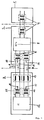
- U K 0 - line interface between the digital switching center 1 and the network termination 2 (NT: Network Terminaton) as well as the S0 subscriber interface between the network termination 2 and the terminals 3 (TE Terminal Equipment).
- U K 0 interface transmitters 4 are used to transmit the information between the digital switching center 1 and the network termination 2 .
- the processing of the digital signals in the network termination 2 is carried out by electronic components 5.
- the network termination also contains the NT interface transformers 6 of the S0 interface.
- the transmission of the digital signals between the network termination 2 and a terminal 3 takes place via the transmission lines 7, 8 and the receiving lines 9, 10.
- the signals are converted via the TE interface transmitter 11 and further processed with electronic components 12.
- the terminal also contains current-compensated radio interference suppression chokes 13.
- the magnetic cores according to the invention are used in the NT interface transmitter 6 and the TE interface transmitter 11 of the S0 interface.
- the terminal devices are partly supplied with power from the digital switching center via the S0 subscriber interface. This is the case, for example, if the terminal is a telephone.
- the remote supply of the terminals is not shown in FIG. 1. It takes place via the center tap 14 of the NT interface transformer 6.
- the feed current is divided equally between the transmission lines 7, 8 and the reception lines 9, 10.
- the different current paths will have different resistances. The reasons for this include, for example, different winding resistances of the transformers and different resistances of the plug contacts of the lines or the connecting cord of a terminal into consideration.
- the transformer In order to ensure the transmission of a digital pulse within the specified pulse mask as required by the standard, the transformer must have an inductance of more than 20 mH even with the specified bias currents. Furthermore, the coupling capacity should be low. The upper limit for this is about 100 pF.
- the amorphous magnetic core materials were produced in the form of thin strips by the melt spin process. This method is well known and does not form the subject of this invention. Toroidal tape cores were then wound from the amorphous tapes. The toroidal cores were then subjected to a heat treatment in the transverse field, ie in a magnetic field parallel to the rotational symmetry axis of the toroidal cores. For this purpose, the cores were heated to a temperature of about 420 ° C. and then cooled at a cooling rate of 0.1 to 3 K / min.
- the magnetic cores according to the invention have magnetostriction values of less than 0.3 * 10 ⁇ 6. This means that the permeability drop due to stresses in the material is very small.
- a magnetic core with the alloy composition Co 68.2 Fe4Si 16.8 B11 was produced by the method described above. Different cooling speeds of 0.2, 0.4 and 1.0 K / min were selected. Table 1 lists the values for the saturation induction Bs, the initial permeability » measured at a frequency of 20 kHz, and the magnetic field strength Ho, at which the permeability has dropped to 70% of the value of the initial permeability.
- the magnetic field strength Ho together with the initial permeability, provides information about the suitability as a transmitter material in the case of a pre-magnetization. Small Ho values mean suitability only with a small bias.
- a magnetic core is listed under No. 11.1, which has an alloy composition outside the claimed range.
- the metalloid content in this example is 20 atom%.
- Table II lists the magnetic values of magnetic cores made of manganese-free alloys.
- the alloys also contain 1.5 atomic% molybdenum.
- a comparison shows that these magnetic cores have smaller Ho values than the manganese-containing magnetic cores according to Example 2.
- the manganese-free magnetic cores with a molybdenum additive can therefore be used advantageously for TE interface transformers 11.
- suitable heat treatment can also achieve high Ho values that allow the use of these magnetic cores in the NT interface transformer 6.
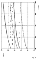
- the relationship between the metalloid content and the initial permeability is shown graphically in FIG.
- the pairs of values represented by rectangles relate to an alloy of the composition Co rest Fe 3.2 Mn 1 (Si 0.6 B 0.4 ) z
- the pairs of values represented by stars refer to an alloy of the composition Co rest Fe 3.8 Mo 1.5 (Si 0.6 B 0.4 ) z. From such an application, particularly advantageous range limits for the metalloid content can be specified depending on the content of other metal alloy components and on the initial permeability.
- the individual metal alloy components of a magnetic core according to the invention are given by: 3 ⁇ a + b ⁇ 8, c ⁇ 15, d ⁇ 1, 0.3 ⁇ x ⁇ 0.7 .
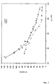
- FIG. 3 shows the relationship between Ho and the initial permeability for manganese-containing and manganese-free magnetic cores according to Examples 2 and 3, respectively.
- the illustration shows that the Ho values are increased by the addition of manganese.
- the manganese-containing magnetic cores can achieve Ho values that are significantly higher than those of the manganese-free magnetic cores.
- the manganese-containing alloys are therefore the preferred magnetic core materials for the claimed interface transformers.
- the manganese-containing alloys are therefore preferred as magnetic core materials, especially for interface transformers with a high DC bias.
- Amorphous cobalt-based alloys containing various combinations of iron, manganese, nickel and molybdenum additives were examined in a further extensive series of tests. The results are summarized in Tab. 3.
- the initial permeability was again measured at a frequency of 20 kHz.
- permeability values in the range from 25,000 to 95,000 can also be achieved with these magnetic cores.
- This often requires a relatively high cooling rate during heat treatment, which is technically more difficult to implement.
- the elements chrome or niobium have the same effect as molybdenum.
- Suitable magnetic cores can therefore also be produced with amorphous cobalt-based alloys which, in addition to cobalt, iron, manganese and metalloids, also contain nickel, molybdenum, chromium or niobium. However, preference is given to alloys which are free from the latter alloy elements.
- Sufficient inductance values and low coupling capacitance values could also be achieved with magnetic cores No. 5.3, 6.3 and 7.3.
- the magnetic cores mentioned have permeability values between 67,000 and 86,000.
- the Ho values are in the range between 26 and 45 mA / cm.
- Fig. 4 the dependence of the inductance on the DC bias for transformers with magnetic cores No. 3.2 and 12.1 is shown graphically. 2 x 19 turns are applied to the magnetic cores.
- the transformer with the manganese-containing magnetic core 3.2 shows a significantly higher direct current load than the transformer with the manganese-free core No. 12.1.
- the transformer with the manganese-containing core no. 3.2 fulfills the ISDN requirements in the specified embodiment up to a direct current bias of approximately 5 mA. It can therefore be used in particular as a TE interface transformer 11.
- Transformers were manufactured with the magnetic cores No. 1.2, 7.1, 9.2, 10.2, 11.1 and 27.1. The transformers in turn had two windings of the same number of turns. The dimensions of the finished component were 14 x 7 x 6 mm. The inductance L (0) without premagnetization and the Inductance with a DC bias of 12 mA and the coupling capacitance C. The measurements were carried out at a frequency of 20 kHz. The results are summarized in Tab. 5.
- the permeability of the cores used as an example is between 34,000 and 39,000.
- the Ho values are in the range between 90 and 108 mA / cm. It can be seen from the comparison with the values from Example 5 that magnetic cores with a lower initial permeability and a higher Ho value must be selected for higher direct current preloads. This can also be seen from the transformers with magnetic core no. 11.1 and 27.1 also listed in Tab. 5.
- FIG. 5 shows the dependency of the inductance on the DC bias for two transmitters with the magnetic cores No. 9.2 and 14.1.
- the transformer with the manganese-free core No. 14.1 fulfills the ISDN requirements for inductance up to a DC current load of around 10 mA.
- the transmitter with the manganese-containing magnetic core No. 9.2 fulfills the ISDN requirements with regard to Inductance up to a DC bias of about 14 mA. With the specified size and number of turns, it can thus be used as an NT interface transformer 6.
- FIG. 5 again illustrates the superiority of the magnetic cores containing manganese with a high direct current preload.
- the magnetic cores according to the invention can thus be used to produce very compact transmitters which meet the ISDN requirements.
- the suitable magnetic cores for the different direct current preloads can easily be selected on the basis of the examples given.
Landscapes
- Engineering & Computer Science (AREA)
- Power Engineering (AREA)
- Physics & Mathematics (AREA)
- Electromagnetism (AREA)
- Chemical & Material Sciences (AREA)
- Dispersion Chemistry (AREA)
- Soft Magnetic Materials (AREA)
- Coils Or Transformers For Communication (AREA)
Claims (5)
- Utilisation d'un noyau magnétique dans lequel le matériau du noyau magnétique est composé d'un alliage à base de Co, amorphe pauvre en magnétostriction, caractérisé en ce que le noyau magnétique est utilisé dans un transformateur d'interface approprié aussi pour la prémagnétisation en courant continu, qui comporte pour la mise en oeuvre dans un système de transmission numérique une inductance L supérieure à 20 mH à 20 kHz pour une capacité de couplage la plus faible possible, en ce que l'alliage à base de Co amorphe contient, en plus du Co, essentiellement du Fe et du Mn avec une teneur totale de 3 à 8 % en atomes ainsi que des métalloïdes avec une teneur de 24 à 29 % en atomes et au choix jusqu'à 15 % en atomes de Ni ainsi que jusqu'à 1 % en atomes de Mo, Cr et/ou Nb et en ce que le matériau de noyau magnétique est soumis à un traitement thermique dans le champ transversal, de sorte qu'il en résulte une perméabilité supérieure à 25 000 et inférieure à 95 000.
- Utilisation d'un noyau magnétique selon la revendication 1, caractérisé en ce que l'alliage à base de Co comprend la composition :
Coreste Fea MnbNic Td (Si1-x (B et/ou C)x)z
dans laquelle:
est au moins l'un des éléments Mo, Cr ou Nb et dans laquelle sont valables pour les quotes-parts d'alliage (en % en atomes) les relations suivantes :




- Utilisation d'un noyau magnétique selon la revendication 2, caractérisé par une proportion de Mn supérieur à 0,5% en atomes (b > 0,5).
- Utilisation d'un noyau magnétique selon la revendication 2, caractérisé en ce que le matériau de noyau magnétique ne contient pas de Ni (c=o).
- Utilisation d'un noyau magnétique selon les revendications 2 ou 4, caractérisé en ce que le matériau de noyau magnétique ne contient pas de Mo, Cr ou Nb (d = o).
Applications Claiming Priority (2)
| Application Number | Priority Date | Filing Date | Title |
|---|---|---|---|
| DE3900946A DE3900946A1 (de) | 1989-01-14 | 1989-01-14 | Magnetkern fuer einen schnittstellen-uebertrager |
| DE3900946 | 1989-01-14 |
Publications (3)
| Publication Number | Publication Date |
|---|---|
| EP0378823A2 EP0378823A2 (fr) | 1990-07-25 |
| EP0378823A3 EP0378823A3 (fr) | 1991-04-03 |
| EP0378823B1 true EP0378823B1 (fr) | 1995-03-15 |
Family
ID=6372069
Family Applications (1)
| Application Number | Title | Priority Date | Filing Date |
|---|---|---|---|
| EP89123354A Expired - Lifetime EP0378823B1 (fr) | 1989-01-14 | 1989-12-18 | Utilisation d'un noyau magnétique dans un transformateur d'interface |
Country Status (3)
| Country | Link |
|---|---|
| EP (1) | EP0378823B1 (fr) |
| JP (1) | JP3229309B2 (fr) |
| DE (2) | DE3900946A1 (fr) |
Families Citing this family (3)
| Publication number | Priority date | Publication date | Assignee | Title |
|---|---|---|---|---|
| EP0927479B1 (fr) * | 1996-09-17 | 2002-04-10 | Vacuumschmelze GmbH | Transformateur d'impulsions pour interfaces en u selon le principe de la compensation d'echo |
| DE19948897A1 (de) * | 1999-10-11 | 2001-04-19 | Vacuumschmelze Gmbh | Schnittstellenmodule für lokale Datennetzwerke |
| JP7003046B2 (ja) * | 2016-09-29 | 2022-01-20 | 株式会社東芝 | 磁心 |
Citations (1)
| Publication number | Priority date | Publication date | Assignee | Title |
|---|---|---|---|---|
| DE3021536A1 (de) * | 1979-06-09 | 1980-12-18 | Matsushita Electric Ind Co Ltd | Amorphe massen mit verbesserten eigenschaften, insbesondere verbesserten magnetischen und kristallisationseigenschaften |
Family Cites Families (5)
| Publication number | Priority date | Publication date | Assignee | Title |
|---|---|---|---|---|
| DE2924280A1 (de) * | 1979-06-15 | 1981-01-08 | Vacuumschmelze Gmbh | Amorphe weichmagnetische legierung |
| US4482400A (en) * | 1980-03-25 | 1984-11-13 | Allied Corporation | Low magnetostriction amorphous metal alloys |
| DE3275492D1 (en) * | 1982-01-18 | 1987-04-02 | Allied Corp | Near-zero magnetostrictive glassy metal alloys with high magnetic and thermal stability |
| JPS6024338A (ja) * | 1983-07-19 | 1985-02-07 | Hitachi Metals Ltd | 非晶質強磁性合金 |
| JPS61243152A (ja) * | 1985-11-29 | 1986-10-29 | Res Inst Iron Steel Tohoku Univ | 高透磁率アモルフアス合金及びその製造法 |
-
1989
- 1989-01-14 DE DE3900946A patent/DE3900946A1/de not_active Withdrawn
- 1989-12-18 DE DE58909115T patent/DE58909115D1/de not_active Expired - Fee Related
- 1989-12-18 EP EP89123354A patent/EP0378823B1/fr not_active Expired - Lifetime
-
1990
- 1990-01-11 JP JP00437990A patent/JP3229309B2/ja not_active Expired - Fee Related
Patent Citations (1)
| Publication number | Priority date | Publication date | Assignee | Title |
|---|---|---|---|---|
| DE3021536A1 (de) * | 1979-06-09 | 1980-12-18 | Matsushita Electric Ind Co Ltd | Amorphe massen mit verbesserten eigenschaften, insbesondere verbesserten magnetischen und kristallisationseigenschaften |
Also Published As
| Publication number | Publication date |
|---|---|
| JPH02271504A (ja) | 1990-11-06 |
| JP3229309B2 (ja) | 2001-11-19 |
| EP0378823A2 (fr) | 1990-07-25 |
| EP0378823A3 (fr) | 1991-04-03 |
| DE58909115D1 (de) | 1995-04-20 |
| DE3900946A1 (de) | 1990-07-26 |
Similar Documents
| Publication | Publication Date | Title |
|---|---|---|
| DE69422862T2 (de) | Nanokristalline Legierung mit Dämpfungskarakteristiken, Herstellungsverfahren desselben, Drosselspule, und Störfilter | |
| DE69408916T2 (de) | Magnetkern für Impulsübertrager und Impulsübertrager | |
| DE3884491T2 (de) | Magnetkern und Verfahren zur Herstellung. | |
| DE60102884T2 (de) | Magnetisches ferritisches Material und Induktor | |
| DE69018422T2 (de) | Auf Eisen basierende weichmagnetische Legierung, ihr Herstellungsverfahren und Magnetkern daraus. | |
| EP1609159B1 (fr) | Noyau magnetique, procede de realisation associe, utilisation d'un noyau magnetique de ce type notamment dans des transformateurs de courant et dans des bobines de choc a compensation de courant, alliages et bandes pour realiser un tel noyau magnetique | |
| DE19714977B4 (de) | Vorrichtung mit Wechselrichter | |
| DE4210748C1 (de) | Stromwandler für pulsstromsensitive Fehlerstromschutzschalter, Fehlerstromschutzschalter mit einem solchen Stromwandler, und Verfahren zur Wärmebehandlung des Eisenlegierungsbandes für dessen Magnetkern | |
| EP0392204B1 (fr) | Application d'un alliage microcristallin à base de fer pour disjoncteur de protection à courant de défaut | |
| EP1058964B1 (fr) | Filtre passe-bas pour diplexeur | |
| EP0809263B1 (fr) | Composant inductif du type plat | |
| DE2928060A1 (de) | Verfahren zur behandlung einer fe-cr-co-magnetlegierung | |
| DE3619659C2 (de) | Verwendung einer glasartigen Legierung auf Fe-Basis | |
| EP0927479B1 (fr) | Transformateur d'impulsions pour interfaces en u selon le principe de la compensation d'echo | |
| EP0378823B1 (fr) | Utilisation d'un noyau magnétique dans un transformateur d'interface | |
| EP0392202B1 (fr) | Application d'un alliage à base de fer, à cristallinité fine comme noyau magnétique pour un transformateur d'interface | |
| DE3888750T2 (de) | Vorrichtung und Verfahren zum Diskriminieren von Signalen. | |
| EP1188235B1 (fr) | Branche passe-haut d'un diplexeur pour systemes lnpa | |
| EP1129459A1 (fr) | Noyau magnetique destine a etre utilise dans un transformateur d'intensite, procede de fabrication d'un noyau magnetique et transformateur d'intensite equipe d'un tel noyau | |
| DE68911223T2 (de) | Weichmagnetische, auf Eisen basierende Legierung. | |
| DE3486331T2 (de) | Kern eines Störungsfilters aus einer amorphen Legierung. | |
| EP0504674B1 (fr) | Transformateur de mesure pour des appareils électroniques détectant rapidement des courts-circuits | |
| DE3620617A1 (de) | Wickelkern | |
| EP0780854A1 (fr) | Bobine de choc d'antiparasitage à compensation en courant | |
| DE69031338T2 (de) | Magnetkern |
Legal Events
| Date | Code | Title | Description |
|---|---|---|---|
| PUAI | Public reference made under article 153(3) epc to a published international application that has entered the european phase |
Free format text: ORIGINAL CODE: 0009012 |
|
| AK | Designated contracting states |
Kind code of ref document: A2 Designated state(s): DE FR GB IT NL SE |
|
| PUAL | Search report despatched |
Free format text: ORIGINAL CODE: 0009013 |
|
| AK | Designated contracting states |
Kind code of ref document: A3 Designated state(s): DE FR GB IT NL SE |
|
| 17P | Request for examination filed |
Effective date: 19910920 |
|
| 17Q | First examination report despatched |
Effective date: 19930201 |
|
| GRAA | (expected) grant |
Free format text: ORIGINAL CODE: 0009210 |
|
| AK | Designated contracting states |
Kind code of ref document: B1 Designated state(s): DE FR GB IT NL SE |
|
| ET | Fr: translation filed | ||
| GBT | Gb: translation of ep patent filed (gb section 77(6)(a)/1977) |
Effective date: 19950314 |
|
| REF | Corresponds to: |
Ref document number: 58909115 Country of ref document: DE Date of ref document: 19950420 |
|
| ITF | It: translation for a ep patent filed | ||
| PLBE | No opposition filed within time limit |
Free format text: ORIGINAL CODE: 0009261 |
|
| STAA | Information on the status of an ep patent application or granted ep patent |
Free format text: STATUS: NO OPPOSITION FILED WITHIN TIME LIMIT |
|
| 26N | No opposition filed | ||
| REG | Reference to a national code |
Ref country code: GB Ref legal event code: IF02 |
|
| PGFP | Annual fee paid to national office [announced via postgrant information from national office to epo] |
Ref country code: GB Payment date: 20021126 Year of fee payment: 14 |
|
| PGFP | Annual fee paid to national office [announced via postgrant information from national office to epo] |
Ref country code: NL Payment date: 20021217 Year of fee payment: 14 |
|
| PGFP | Annual fee paid to national office [announced via postgrant information from national office to epo] |
Ref country code: SE Payment date: 20021227 Year of fee payment: 14 |
|
| PG25 | Lapsed in a contracting state [announced via postgrant information from national office to epo] |
Ref country code: GB Free format text: LAPSE BECAUSE OF NON-PAYMENT OF DUE FEES Effective date: 20031218 |
|
| PG25 | Lapsed in a contracting state [announced via postgrant information from national office to epo] |
Ref country code: SE Free format text: LAPSE BECAUSE OF NON-PAYMENT OF DUE FEES Effective date: 20031219 |
|
| PG25 | Lapsed in a contracting state [announced via postgrant information from national office to epo] |
Ref country code: NL Free format text: LAPSE BECAUSE OF NON-PAYMENT OF DUE FEES Effective date: 20040701 |
|
| EUG | Se: european patent has lapsed | ||
| GBPC | Gb: european patent ceased through non-payment of renewal fee |
Effective date: 20031218 |
|
| NLV4 | Nl: lapsed or anulled due to non-payment of the annual fee |
Effective date: 20040701 |
|
| PGFP | Annual fee paid to national office [announced via postgrant information from national office to epo] |
Ref country code: FR Payment date: 20041221 Year of fee payment: 16 |
|
| PG25 | Lapsed in a contracting state [announced via postgrant information from national office to epo] |
Ref country code: IT Free format text: LAPSE BECAUSE OF NON-PAYMENT OF DUE FEES Effective date: 20051218 |
|
| PG25 | Lapsed in a contracting state [announced via postgrant information from national office to epo] |
Ref country code: FR Free format text: LAPSE BECAUSE OF NON-PAYMENT OF DUE FEES Effective date: 20060831 |
|
| REG | Reference to a national code |
Ref country code: FR Ref legal event code: ST Effective date: 20060831 |
|
| PGFP | Annual fee paid to national office [announced via postgrant information from national office to epo] |
Ref country code: DE Payment date: 20070126 Year of fee payment: 18 |
|
| PG25 | Lapsed in a contracting state [announced via postgrant information from national office to epo] |
Ref country code: DE Free format text: LAPSE BECAUSE OF NON-PAYMENT OF DUE FEES Effective date: 20080701 |