EP0378965A1 - Stoffdrückfussvorrichtung für eine Nähmaschine - Google Patents
Stoffdrückfussvorrichtung für eine Nähmaschine Download PDFInfo
- Publication number
- EP0378965A1 EP0378965A1 EP89810850A EP89810850A EP0378965A1 EP 0378965 A1 EP0378965 A1 EP 0378965A1 EP 89810850 A EP89810850 A EP 89810850A EP 89810850 A EP89810850 A EP 89810850A EP 0378965 A1 EP0378965 A1 EP 0378965A1
- Authority
- EP
- European Patent Office
- Prior art keywords
- lever
- sole
- carriage
- jack
- foot
- Prior art date
- Legal status (The legal status is an assumption and is not a legal conclusion. Google has not performed a legal analysis and makes no representation as to the accuracy of the status listed.)
- Granted
Links
Images


Classifications
-
- D—TEXTILES; PAPER
- D05—SEWING; EMBROIDERING; TUFTING
- D05B—SEWING
- D05B29/00—Pressers; Presser feet
- D05B29/02—Presser-control devices
-
- D—TEXTILES; PAPER
- D05—SEWING; EMBROIDERING; TUFTING
- D05B—SEWING
- D05B19/00—Program-controlled sewing machines
Definitions
- the subject of the present invention is a presser device for a sewing machine, comprising, on the one hand, a rocking lever whose free end carries a presser foot and, on the other hand, an actuation device making it possible to drive this lever at least in two limit angular positions, one, low, in which the foot is applied to the material to be sewn, the other, high, in which it is distant.
- the stuffing device is characterized in that the other end of the lever carries at least one rolling member resting on a guide ramp, the profile of the latter and / or of the portion of said member in contact at all times with the ramp being such that, when the lever is tilted from one of its limit angular positions in the other thereof, the foot fixed to the lever moves on a substantially vertical trajectory.
- Claims 2 to 11 define other important characteristics of the stuffing device according to the invention.
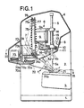
- 1 is the base of the housing of a ma sewing machine on which stands a column 2 carrying two arms 3 and 4 of which the first, 3, contains in particular a loop sensor and its control mechanism as well as a device for driving the material to be sewn, all not visible, and whose second arm, 4, carries a mechanism, not shown, for controlling the sliding, alternately in two opposite directions, of a needle bar 5, as well as a device 6 for driving this bar 5 in its throwing movement and a stuffing device 7 whose features will be described below.
- the central motor of the sewing machine on which depend in particular the drive of the loop sensor, that of the material to be sewn and that of the bi-directional vertical movement of the needle bar, is arranged in column 2, at sides of a step-down transformer and of a rectifier assembly, all not visible in the drawing, for the current supply of the motor as well as an electronic circuit, not shown, grouping in the form of "solid state” chips, information storage memories programmed for controlling the various functions of the sewing machine, and one or more microprocessors on which this control depends. All of these means, their coupling and functions are well known to those skilled in the art and will not be described here.
- the sewing machine shown On its casing, and more particularly on its right front face in the drawing, the sewing machine shown carries a control keyboard of which only a switch 8, for actuating the stuffing device 7, has been shown in FIG. 1.
- the device 6 is of the type described in the Swiss patent N °, (request filed by the holder jointly with the present request) to which reference will be made for the structural details.
- a stepping motor 9 with a vertical axis, for controlling the tilting of a lever 10, articulated at 11 on a fixed support 12 and having a frustoconical opening forming a seat for the external face, with a spherical profile, of a bearing 13, arranged in line with a second bearing 14, of structure identical to that of the bearing 13 and engaged in a corresponding seat formed in the upper flange 9a of the motor 9.
- the bearings 13 and 14 are held in their respective seats by a spring 15, stretched between these bearings and crossed, like the bearings themselves, by the needle bar 5, the latter being moreover mounted to slide in these bearings.
- a lamp 16 Under the support 12 is fixed a lamp 16 ensuring the lighting of the sewing area of the arm 3 through a window 4a formed in the wall of the arm 4.
- a second window 4b of oblong shape, ensures the passage of the needle bar 5 and allows its throwing movements.
- the presser device 7 comprises (fig. 1) a lever 70 at the right end of which is articulated, by an axis 70a, a presser foot 71 located below the needle bar 5 and that the lever 70 is intended to drive either in a low position, shown in solid lines, in which the foot presses the material to be sewn onto a needle plate 3a which has the upper face of the arm 3 of the machine (fig. 3) and more precisely on the claw , not shown, for driving the sewing material, from right to left in the drawing or vice-versa, either in a high position, shown in phantom, which is vertical to that occupied by the foot 71, in the low position .
- the material to be sewn can be moved freely by hand, in particular to position the part to receive the seam under the needle 5a carried by the needle bar 5.
- the stuffing device according to the invention allows the execution of seams in a very thick fabric, even becoming suddenly irregular, without blocking of this fabric by the foot 71.
- the lever 70 can easily switch in one or the other of two directions F1 and F2 even when the foot 71 is applied to the fabric to be sewn, which explains the ease with which the machine sewing machine shown can sew stacks of fabric even of substantial thickness.
- the lever 70 carries, on its left part (fig. 1), a flat and rectangular sole, 70b, projecting on each side of the lever and having, along its two longitudinal edges, two toothed sectors 70c and 70d each resting on a straight track specific to each sector, 72a, respectively 72b (figs 1 and 2) with toothed profile, cut on the upper face of a console 72 secured to the frame, partially shown of the sewing machine.
- the pitch and the shape of the toothing of the toothed sectors 70c and 70d and those of the rolling tracks 72a and 72b are identical, the toothing of the former perfectly meshing with that of the latter.
- the actuation of the lever 10 can be obtained either by means of a motorized control, such as that shown in Figures 1 and 8 in particular, or even by manual control, of the type visible in Figs 4 and 6 for example. It is, of course, possible to provide only the second of these possibilities, in particular in the case of low-end sewing machines, or, on the contrary, that the first, for high-performance sewing machines, such as in particular electronic microprocessor sewing machines. Alternatively, such a type of machine could include both motorized control and manual control of the stuffing device according to the invention.
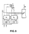
- this device comprises a stepping motor 73 whose windings E1 and E2 (fig. 8) are supplied, in an appropriate manner, by "drivers" D1 and D2 controlled by a microprocessor ⁇ P, which, in a computerized sewing machine, can also be used for general control of the machine's functions.
- the actuation of the switch 8 causes the impulse type information to be sent to the microprocessor alternately determining the commissioning of the driver D1 or of the driver D2 for a period of time sufficient to drive the foot 71 from its low position to its position high, and vice versa.
- the housing of the motor 73 carries a barrel 73a, articulated on the housing of the sewing machine by means of two axes 73b (figs 1 and 3) projecting from the barrel 73a, on either side thereof. .
- This barrel is crossed by the left end, in the drawing, of a threaded rod 73c extending in the extension of the shaft, not shown, of the motor, integral with this shaft, and engaged in a threaded passage 74a that has an axis 74c carrying two rollers 74b and forming part of a carriage 74 capable of rolling on the sole 70b of the lever 70, and the right end of the latter at its left end and vice versa, according to the direction of rotation of the threaded rod 73c, that is to say of the armature of the stepping motor.
- the length of the carriage stroke on the sole 70b is fixed by the number of control pulses sent by the drivers D1 and D2 on the windings E1 and E2 each time the switch 8 is actuated. This number will obviously be identical for each driver so that the stroke of the carriage will be the same in one direction or the other of its movement on the sole 70b.
- the carriage 74 is fixed to the lower end of a bar 75 whose upper end, forked at 75a, slidably embraces a guide rod 76 fixed horizontally to the housing of the machine.
- a spring 76 prestressed between the rod 77 and the carriage 74 on which it rests and whose length is such that it remains under tension even when the bar 75 which carries it is disposed in its position inclined, shown in phantom in the drawing.
- the assembly formed by the bar 75, the rod 76 and the spring 77 form a sort of thrust cylinder exerting its action on the sole 70b of the lever 70 of which it will determine the angular position according to the position occupied at all times by the carriage 74 on the sole 70b. It will be recalled that the latter can be moved on this sole by rotation of the threaded rod 73c in one direction or the other, according to the direction desired for the movement of the carriage 74.
- the lever 70 will resume its low position as soon as, by a movement in the opposite direction of the carriage 74, the same vertical component of the force exerted by the spring 77 will pass to the right the support area of this lever.
- the foot 71 and the lever 70 will be lifted quantity corresponding to this thickness: at the limit, the lever 70 and its foot 71 may even be temporarily driven into the high position shown in phantom in the drawing, giving way to the excess thickness of the material to be sewn without there being machine blocked.
- the bar 75 will rise vertically by sliding its forked end 75a on the rod 76 and compressing the spring 77.
- This bar will return to its usual axial position, smoothly, by relaxation of the spring 77, as soon as the foot 71 has passed over the temporary excess thickness of the material to be sewn.
- the foot 71 and the lever 70 are somehow mounted on a real suspension allowing them to easily absorb all the obstacles that may present to them the surface of a sewing piece, even of relatively high thickness as is for example the case when it is a question of assembling several layers of coarse Jean type canvas or corduroy for example.
- the stuffing device according to the invention may also include only a manual control of the kind illustrated by way of example in FIGS. 4 to 6.
- Such a device differs from that described with reference to FIGS. 1 to 3 and 8 by the fact that the motor 73 and its annexed parts as well as the circuit which is the subject of FIG. 8 are deleted, with the corresponding modifications for the sewing machine housing especially. Therefore, the carriage 74 * on the sole 70b * of the lever 70 * will be carried out by corresponding horizontal displacement, carried out manually, of a pull tab 78 * secured to the carriage 70 * b and passing through a slot f made in the machine housing, pull tab that the user can control by finger action on a button 78 * fixed to the free end of the latter (figs 1 and 6).
- the stroke of the carriage 74 * on the sole 70 * b of the lever 70 * is limited by meeting the rollers 74 * b with two pairs of stops, 70 * d and 70 * e alternately depending on the direction of movement of this carriage (fig. 5).
- the rolling tracks 172 intended for the toothed sectors 170c of the lever 170 carrying the foot 171 could be cut from a single piece 180 constituting at the same time the lower flange of a motor step by step 190 for controlling the throwing movement of the machine needle bar.
- the upper flange of this motor, 180 * would include a fork 180 * a at the end of which would be fixed the rod 176 allowing the axial sliding of the bar 175 of the pressure cylinder formed by this bar in cooperation with a coil spring 177.
- the solution mentioned above makes it possible to combine the stuffing device according to the invention, the device for controlling the throwing of the needle bar and this needle bar to form a single aggregate, capable of being manufactured and mounted of independently, independently of the rest of the sewing machine, even in a workshop or factory distant from the final assembly location and at a time different from that of this assembly.
- the adaptation mentioned above could be automatic thanks to a computerized program operated by the microprocessor of the circuit (figg. 8) and which would be accessible from various control keys, each corresponding at a different position of the jack on the sole 70b, respectively 170b (figs 1 and 7), that is to say at an optimal pressure exerted by the presser foot of the machine on the material to be sewn, according to the characteristics which give it are clean and the nature of the sewing pattern.
Landscapes
- Engineering & Computer Science (AREA)
- Textile Engineering (AREA)
- Sewing Machines And Sewing (AREA)
Applications Claiming Priority (2)
| Application Number | Priority Date | Filing Date | Title |
|---|---|---|---|
| CH4437/88A CH677508A5 (de) | 1988-11-30 | 1988-11-30 | |
| CH4437/88 | 1988-11-30 |
Publications (2)
| Publication Number | Publication Date |
|---|---|
| EP0378965A1 true EP0378965A1 (de) | 1990-07-25 |
| EP0378965B1 EP0378965B1 (de) | 1993-09-08 |
Family
ID=4276114
Family Applications (1)
| Application Number | Title | Priority Date | Filing Date |
|---|---|---|---|
| EP89810850A Expired - Lifetime EP0378965B1 (de) | 1988-11-30 | 1989-11-08 | Stoffdrückfussvorrichtung für eine Nähmaschine |
Country Status (14)
| Country | Link |
|---|---|
| US (1) | US5042406A (de) |
| EP (1) | EP0378965B1 (de) |
| JP (1) | JPH02182287A (de) |
| CN (1) | CN1024026C (de) |
| AU (1) | AU619062B2 (de) |
| BR (1) | BR8906059A (de) |
| CA (1) | CA2004066A1 (de) |
| CH (1) | CH677508A5 (de) |
| DD (1) | DD296124A5 (de) |
| DE (1) | DE68909031T2 (de) |
| ES (1) | ES2045547T3 (de) |
| PT (1) | PT92427B (de) |
| RU (1) | RU1834933C (de) |
| ZA (1) | ZA899037B (de) |
Cited By (2)
| Publication number | Priority date | Publication date | Assignee | Title |
|---|---|---|---|---|
| US5143006A (en) * | 1989-10-13 | 1992-09-01 | Mefina S.A. | Assembly for detachably mounting a tool on a driving member |
| US5205230A (en) * | 1990-11-29 | 1993-04-27 | Mefina S.A. | Sewing machine |
Families Citing this family (9)
| Publication number | Priority date | Publication date | Assignee | Title |
|---|---|---|---|---|
| DE19918169A1 (de) * | 1999-04-21 | 2000-10-26 | Zsk Stickmasch Gmbh | Höheneinstellung eines Stoffdrückers |
| US6170414B1 (en) | 1999-05-07 | 2001-01-09 | L&P Property Management Company | Quilting machine with adjustable presser plate and method of operating the quilting machine |
| US6145456A (en) * | 1999-05-07 | 2000-11-14 | L&P Property Management Company | Quilting machine with adjustable presser plate and method of operating the quilting machine |
| JP4185393B2 (ja) * | 2003-04-16 | 2008-11-26 | ペガサスミシン製造株式会社 | ミシンのプレッサ装置 |
| JP4478991B2 (ja) * | 2008-02-15 | 2010-06-09 | ヤマトミシン製造株式会社 | ミシンの押え揚げ装置 |
| DE102008016353A1 (de) * | 2008-03-29 | 2009-10-08 | Dürkopp Adler AG | Nähmaschine |
| JP6552233B2 (ja) * | 2015-03-20 | 2019-07-31 | 蛇の目ミシン工業株式会社 | ミシン |
| CN110396775B (zh) * | 2019-08-19 | 2024-06-04 | 宁波申洲针织有限公司 | 一种自动拼下摆罗纹装置 |
| CN113502607A (zh) * | 2021-08-11 | 2021-10-15 | 东莞诺德科技有限公司 | 一种女士皮包的自动打孔缝线设备 |
Citations (7)
| Publication number | Priority date | Publication date | Assignee | Title |
|---|---|---|---|---|
| US1602140A (en) * | 1923-12-31 | 1926-10-05 | Samuel W Avis | Presser-foot mechanism for sewing machines |
| FR614104A (fr) * | 1925-04-07 | 1926-12-07 | Junker & Ruh G M B H | Presse-ouvrage pour machines à coudre les chaussures et le cuir |
| US2238796A (en) * | 1939-06-10 | 1941-04-15 | Singer Mfg Co | Overedge sewing machine |
| US2241778A (en) * | 1939-06-02 | 1941-05-13 | Giancola Nicholas | Presser foot and multiple gauge for sewing machines |
| US3437062A (en) * | 1966-10-11 | 1969-04-08 | Singer Co | Mechanism for automatically adjusting the height of a top feed foot |
| DE3119716C1 (de) * | 1981-05-18 | 1982-11-04 | Pfaff Industriemaschinen Gmbh, 6750 Kaiserslautern | Obertransporteinrichtung an einer Naehmaschine |
| US4480566A (en) * | 1983-08-25 | 1984-11-06 | The Singer Company | Mending attachment for a sewing machine |
Family Cites Families (6)
| Publication number | Priority date | Publication date | Assignee | Title |
|---|---|---|---|---|
| US4166422A (en) * | 1978-09-06 | 1979-09-04 | Porter Robert E | Top feed for sewing machine |
| JPS6332704Y2 (de) * | 1979-07-04 | 1988-08-31 | ||
| US4214543A (en) * | 1979-07-05 | 1980-07-29 | The Singer Company | Electronically controlled top feed arrangement for a sewing machine |
| GB2071170B (en) * | 1980-01-31 | 1983-08-17 | Brother Ind Ltd | Work presser device for sewing machine |
| JPS57107187A (en) * | 1980-12-25 | 1982-07-03 | Tokyo Juki Industrial Co Ltd | Upward feeding mechanism of sewing machine |
| DE3528295A1 (de) * | 1985-08-07 | 1987-02-19 | Pfaff Ind Masch | Naehmaschine mit einer abtastvorrichtung |
-
1988
- 1988-11-30 CH CH4437/88A patent/CH677508A5/fr not_active IP Right Cessation
-
1989
- 1989-11-08 DE DE89810850T patent/DE68909031T2/de not_active Expired - Fee Related
- 1989-11-08 EP EP89810850A patent/EP0378965B1/de not_active Expired - Lifetime
- 1989-11-08 ES ES89810850T patent/ES2045547T3/es not_active Expired - Lifetime
- 1989-11-27 ZA ZA899037A patent/ZA899037B/xx unknown
- 1989-11-28 DD DD89334935A patent/DD296124A5/de not_active IP Right Cessation
- 1989-11-28 PT PT92427A patent/PT92427B/pt not_active IP Right Cessation
- 1989-11-28 CA CA002004066A patent/CA2004066A1/fr not_active Abandoned
- 1989-11-29 AU AU45699/89A patent/AU619062B2/en not_active Ceased
- 1989-11-29 JP JP1307860A patent/JPH02182287A/ja active Pending
- 1989-11-29 RU SU894742456A patent/RU1834933C/ru active
- 1989-11-30 BR BR898906059A patent/BR8906059A/pt unknown
- 1989-11-30 CN CN89109015A patent/CN1024026C/zh not_active Expired - Fee Related
- 1989-11-30 US US07/443,326 patent/US5042406A/en not_active Expired - Fee Related
Patent Citations (7)
| Publication number | Priority date | Publication date | Assignee | Title |
|---|---|---|---|---|
| US1602140A (en) * | 1923-12-31 | 1926-10-05 | Samuel W Avis | Presser-foot mechanism for sewing machines |
| FR614104A (fr) * | 1925-04-07 | 1926-12-07 | Junker & Ruh G M B H | Presse-ouvrage pour machines à coudre les chaussures et le cuir |
| US2241778A (en) * | 1939-06-02 | 1941-05-13 | Giancola Nicholas | Presser foot and multiple gauge for sewing machines |
| US2238796A (en) * | 1939-06-10 | 1941-04-15 | Singer Mfg Co | Overedge sewing machine |
| US3437062A (en) * | 1966-10-11 | 1969-04-08 | Singer Co | Mechanism for automatically adjusting the height of a top feed foot |
| DE3119716C1 (de) * | 1981-05-18 | 1982-11-04 | Pfaff Industriemaschinen Gmbh, 6750 Kaiserslautern | Obertransporteinrichtung an einer Naehmaschine |
| US4480566A (en) * | 1983-08-25 | 1984-11-06 | The Singer Company | Mending attachment for a sewing machine |
Cited By (2)
| Publication number | Priority date | Publication date | Assignee | Title |
|---|---|---|---|---|
| US5143006A (en) * | 1989-10-13 | 1992-09-01 | Mefina S.A. | Assembly for detachably mounting a tool on a driving member |
| US5205230A (en) * | 1990-11-29 | 1993-04-27 | Mefina S.A. | Sewing machine |
Also Published As
| Publication number | Publication date |
|---|---|
| DE68909031T2 (de) | 1994-04-21 |
| CN1024026C (zh) | 1994-03-16 |
| RU1834933C (ru) | 1993-08-15 |
| ZA899037B (en) | 1990-09-26 |
| CN1043171A (zh) | 1990-06-20 |
| CH677508A5 (de) | 1991-05-31 |
| PT92427B (pt) | 1995-08-09 |
| US5042406A (en) | 1991-08-27 |
| CA2004066A1 (fr) | 1990-05-31 |
| DD296124A5 (de) | 1991-11-21 |
| PT92427A (pt) | 1990-05-31 |
| AU619062B2 (en) | 1992-01-16 |
| AU4569989A (en) | 1990-06-07 |
| EP0378965B1 (de) | 1993-09-08 |
| BR8906059A (pt) | 1990-06-19 |
| ES2045547T3 (es) | 1994-01-16 |
| JPH02182287A (ja) | 1990-07-16 |
| DE68909031D1 (de) | 1993-10-14 |
Similar Documents
| Publication | Publication Date | Title |
|---|---|---|
| EP0378965B1 (de) | Stoffdrückfussvorrichtung für eine Nähmaschine | |
| EP0804888B1 (de) | Verbesserungen an Verstell- und Bedienungsvorrichtungen von bewegenden und verformbaren Teilen eines Bürostuhls | |
| US6569001B2 (en) | Power tool having a quick clamping mechanism | |
| EP0809457B1 (de) | Elektrisch betriebener handschläger und -rührer | |
| FR2461613A1 (fr) | Appui-tete reglable en hauteur pour siege d'automobile | |
| EP0377404B1 (de) | Zickzack-Nähmaschine | |
| FR2644096A1 (fr) | Machine a couper les carreaux, notamment de gres | |
| EP0521760B1 (de) | Vorrichtung zur Einstellung des Arbeitseffekts der Steuerorgane eines Luftfahrzeuges | |
| FR2709800A1 (fr) | Mitigeur monocommande pour salles de bains. | |
| FR2705129A1 (fr) | Dispositif formant commande de vitesses pour boîte de vitesses automatique de véhicule. | |
| FR2723333A1 (fr) | Dispositif de marquage pour la realisation de signes d'identification a deux dimensions sur la surface d'un objet quelconque | |
| EP0122222B1 (de) | Nähmaschine | |
| WO2008110669A1 (fr) | Mecanisme de reglage synchronise de la tension de basculement d'un siege | |
| CH677804A5 (de) | ||
| EP0020184B1 (de) | Nähmaschinen mit automatischer Werkstückführung | |
| WO1994001022A1 (fr) | Literie constituee d'un sommier a dossier relevable et matelas adapte | |
| FR2756230A1 (fr) | Dispositif d'actionnement d'un organe de commande d'un mecanisme de siege de vehicule automobile et siege muni d'un tel dispositif | |
| FR2538422A1 (fr) | Module de commande a boutons-poussoirs pour machines a coudre | |
| FR2680653A1 (fr) | Appareil d'epilation. | |
| EP0250303B1 (de) | Schalter zum Ansteuern von Leuchten in Kraftfahrzeugen | |
| FR2634294A1 (fr) | Dispositif de commande a position neutre reglable | |
| FR2544098A1 (fr) | Programmateur | |
| FR2700934A3 (fr) | Meuble pous s'asseoir ou s'allonger ayant la forme d'une ottomane ou d'un récamier. | |
| EP1046963B1 (de) | Tastschaltermechanismus und mit solchen Mechanismen ausgerüstete Uhr | |
| FR2688326A1 (fr) | Dispositif de commande. |
Legal Events
| Date | Code | Title | Description |
|---|---|---|---|
| PUAI | Public reference made under article 153(3) epc to a published international application that has entered the european phase |
Free format text: ORIGINAL CODE: 0009012 |
|
| AK | Designated contracting states |
Kind code of ref document: A1 Designated state(s): DE ES FR GB IT SE |
|
| 17P | Request for examination filed |
Effective date: 19900906 |
|
| 17Q | First examination report despatched |
Effective date: 19920128 |
|
| GRAA | (expected) grant |
Free format text: ORIGINAL CODE: 0009210 |
|
| AK | Designated contracting states |
Kind code of ref document: B1 Designated state(s): DE ES FR GB IT SE |
|
| REF | Corresponds to: |
Ref document number: 68909031 Country of ref document: DE Date of ref document: 19931014 |
|
| PGFP | Annual fee paid to national office [announced via postgrant information from national office to epo] |
Ref country code: GB Payment date: 19931101 Year of fee payment: 5 |
|
| PGFP | Annual fee paid to national office [announced via postgrant information from national office to epo] |
Ref country code: FR Payment date: 19931116 Year of fee payment: 5 |
|
| ITF | It: translation for a ep patent filed | ||
| PGFP | Annual fee paid to national office [announced via postgrant information from national office to epo] |
Ref country code: SE Payment date: 19931123 Year of fee payment: 5 |
|
| PGFP | Annual fee paid to national office [announced via postgrant information from national office to epo] |
Ref country code: ES Payment date: 19931124 Year of fee payment: 5 |
|
| PGFP | Annual fee paid to national office [announced via postgrant information from national office to epo] |
Ref country code: DE Payment date: 19931130 Year of fee payment: 5 |
|
| GBT | Gb: translation of ep patent filed (gb section 77(6)(a)/1977) |
Effective date: 19931130 |
|
| REG | Reference to a national code |
Ref country code: ES Ref legal event code: FG2A Ref document number: 2045547 Country of ref document: ES Kind code of ref document: T3 |
|
| PLBE | No opposition filed within time limit |
Free format text: ORIGINAL CODE: 0009261 |
|
| STAA | Information on the status of an ep patent application or granted ep patent |
Free format text: STATUS: NO OPPOSITION FILED WITHIN TIME LIMIT |
|
| 26N | No opposition filed | ||
| PG25 | Lapsed in a contracting state [announced via postgrant information from national office to epo] |
Ref country code: GB Effective date: 19941108 |
|
| PG25 | Lapsed in a contracting state [announced via postgrant information from national office to epo] |
Ref country code: SE Effective date: 19941109 Ref country code: ES Free format text: LAPSE BECAUSE OF NON-PAYMENT OF DUE FEES Effective date: 19941109 |
|
| EAL | Se: european patent in force in sweden |
Ref document number: 89810850.1 |
|
| GBPC | Gb: european patent ceased through non-payment of renewal fee |
Effective date: 19941108 |
|
| PG25 | Lapsed in a contracting state [announced via postgrant information from national office to epo] |
Ref country code: FR Effective date: 19950731 |
|
| PG25 | Lapsed in a contracting state [announced via postgrant information from national office to epo] |
Ref country code: DE Effective date: 19950801 |
|
| EUG | Se: european patent has lapsed |
Ref document number: 89810850.1 |
|
| REG | Reference to a national code |
Ref country code: FR Ref legal event code: ST |
|
| REG | Reference to a national code |
Ref country code: ES Ref legal event code: FD2A Effective date: 19951214 |
|
| PG25 | Lapsed in a contracting state [announced via postgrant information from national office to epo] |
Ref country code: IT Free format text: LAPSE BECAUSE OF NON-PAYMENT OF DUE FEES;WARNING: LAPSES OF ITALIAN PATENTS WITH EFFECTIVE DATE BEFORE 2007 MAY HAVE OCCURRED AT ANY TIME BEFORE 2007. THE CORRECT EFFECTIVE DATE MAY BE DIFFERENT FROM THE ONE RECORDED. Effective date: 20051108 |