EP0379426A2 - Verfahren und Vorrichtung zum Schleifen einer Linse - Google Patents
Verfahren und Vorrichtung zum Schleifen einer Linse Download PDFInfo
- Publication number
- EP0379426A2 EP0379426A2 EP90400126A EP90400126A EP0379426A2 EP 0379426 A2 EP0379426 A2 EP 0379426A2 EP 90400126 A EP90400126 A EP 90400126A EP 90400126 A EP90400126 A EP 90400126A EP 0379426 A2 EP0379426 A2 EP 0379426A2
- Authority
- EP
- European Patent Office
- Prior art keywords
- lens
- edge
- grinding
- entire circumference
- finding
- Prior art date
- Legal status (The legal status is an assumption and is not a legal conclusion. Google has not performed a legal analysis and makes no representation as to the accuracy of the status listed.)
- Withdrawn
Links
- 238000000227 grinding Methods 0.000 title claims abstract description 36
- 238000000034 method Methods 0.000 title claims abstract description 19
- 238000007688 edging Methods 0.000 claims abstract description 11
- 230000000750 progressive effect Effects 0.000 abstract description 2
- 239000000945 filler Substances 0.000 description 5
- 238000010276 construction Methods 0.000 description 4
- 238000005520 cutting process Methods 0.000 description 4
- 238000010586 diagram Methods 0.000 description 3
- 230000008093 supporting effect Effects 0.000 description 3
- 230000003287 optical effect Effects 0.000 description 2
- 229920000136 polysorbate Polymers 0.000 description 2
- 238000007796 conventional method Methods 0.000 description 1
- 238000012986 modification Methods 0.000 description 1
- 230000004048 modification Effects 0.000 description 1
- 230000002250 progressing effect Effects 0.000 description 1
Images


Classifications
-
- B—PERFORMING OPERATIONS; TRANSPORTING
- B24—GRINDING; POLISHING
- B24B—MACHINES, DEVICES, OR PROCESSES FOR GRINDING OR POLISHING; DRESSING OR CONDITIONING OF ABRADING SURFACES; FEEDING OF GRINDING, POLISHING, OR LAPPING AGENTS
- B24B47/00—Drives or gearings; Equipment therefor
- B24B47/22—Equipment for exact control of the position of the grinding tool or work at the start of the grinding operation
- B24B47/225—Equipment for exact control of the position of the grinding tool or work at the start of the grinding operation for bevelling optical work, e.g. lenses
-
- B—PERFORMING OPERATIONS; TRANSPORTING
- B24—GRINDING; POLISHING
- B24B—MACHINES, DEVICES, OR PROCESSES FOR GRINDING OR POLISHING; DRESSING OR CONDITIONING OF ABRADING SURFACES; FEEDING OF GRINDING, POLISHING, OR LAPPING AGENTS
- B24B9/00—Machines or devices designed for grinding edges or bevels on work or for removing burrs; Accessories therefor
- B24B9/02—Machines or devices designed for grinding edges or bevels on work or for removing burrs; Accessories therefor characterised by a special design with respect to properties of materials specific to articles to be ground
- B24B9/06—Machines or devices designed for grinding edges or bevels on work or for removing burrs; Accessories therefor characterised by a special design with respect to properties of materials specific to articles to be ground of non-metallic inorganic material, e.g. stone, ceramics, porcelain
- B24B9/08—Machines or devices designed for grinding edges or bevels on work or for removing burrs; Accessories therefor characterised by a special design with respect to properties of materials specific to articles to be ground of non-metallic inorganic material, e.g. stone, ceramics, porcelain of glass
- B24B9/14—Machines or devices designed for grinding edges or bevels on work or for removing burrs; Accessories therefor characterised by a special design with respect to properties of materials specific to articles to be ground of non-metallic inorganic material, e.g. stone, ceramics, porcelain of glass of optical work, e.g. lenses, prisms
- B24B9/144—Machines or devices designed for grinding edges or bevels on work or for removing burrs; Accessories therefor characterised by a special design with respect to properties of materials specific to articles to be ground of non-metallic inorganic material, e.g. stone, ceramics, porcelain of glass of optical work, e.g. lenses, prisms the spectacles being used as a template
Definitions
- This invention relates to a lens grinding method for grinding an uncut lens in such a manner as to correspond to the shape of a lens frame of a spectacle frame in order to fit the lens into the lens frame, and an apparatus for carrying out the method.
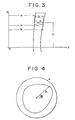
- the lens-edge thickness ⁇ i of an uncut lens L is measured in accordance with the radius vector ( ⁇ i , ⁇ i ) of the locus 1 of the lens shape in order to obtain the maximum lens-edge thickness ⁇ max and the mini
- the spherical radius eR including the V-edge locus Y or focus Y for dividing the both lens-edge thicknesses at a desired ratio 1 :m is obtained by calculation. Then, the amount required for moving the lens L in the Z-axis direction (the direction of the optical axis of the lens), that is, the V-edge cutting information (eZ i , ⁇ i , ⁇ i ) is found from such obtained radius eR and the lens frame shape locus ( ⁇ i, ⁇ i) in order to bring the vertex of the V-edge onto the V-edge locus Y when the lens is subjected to the V-edge cutting.
- the V-edge cutting information eZ i , ⁇ i , ⁇ i
- the V-edge locus Y is included on the spherical surface of the radius eR. Therefore, as is shown in Fig. 8, for example, it has such a disadvantage as that in a progressivelysive multifocus lens L′, a portion for seeing a near place or near sight portion having an aspherical surface NS, if a V-edge y is going to be formed on the lens-edge of a portion for seeing a far place or far sight portion in a position at the ratio of 1 :m, the V-edge cannot be formed on the lens-edge of the near sight portion.
- a lens grinding method of the present invention includes a first step for finding a lens-edge thickness over the entire circumference of a lens-edge vector radius locus of a lens to be cut , a second step for finding a lens-edge vertex position information for dividing said lens-edge into a desired ratio over the entire circumference thereof, and a third step for V-edge edging said lens-edge based on said V-edge vertex position information.
- Said lens-edge vector radius is given from said vector radius information of a lens frame of a spectacle frame into which said lens is to be fitted.
- Said first step finds said lens-edge thickness of said lens which is uncut.
- Said vector radius locus is an locus of a cut lens-edge obtained by grinding using a template which has a pattern formed as same as the shape of said spectacle.
- Said first step finds said lens-edge thickness of a lens-edge which is cut.
- a lens grinding apparatus includes measuring means for finding a lens-edge thickness over the entire circumference of a lens-edge vector radius locus of a lens to be cut , input means for inputting a desired ratio, calculating means for finding a positional information of a V-edge vertex for dividing said lens-edge at said input ratio over the entire circumference thereof, and controlling means for V-edge edging said lens-edge based on said V-edge vertex positional information.
- Said lens-edge vector radius is given from said vector radius information of a lens frame of a spectacle frame into which said lens is to be fitted.
- Said first step finds said lens-edge thickness of said lens which is uncut.
- Said vector radius locus is an locus of a cut lens-edge obtained by grinding using a template which has a pattern formed as same as the shape of said spectacle.
- Said first step finds said lens-edge thickness of a lens-edge which is cut.
- Fig.s 1 and 2 are block diagrams showing the first embodiment of the present invention.
- the numeral 10 denotes a frame shape measuring apparatus, and 12 denotes a lens-edge thickness measuring apparatus.
- This frame shape measuring apparatus 10 has the same construction and operation as the apparatus described in the application previously filed by the present applicant, i.e., Japanese Patent Application No. Sho 60-287491.
- This frame shape measuring apparatus 10 measures the shape of the lens frame of a spectacle frame into which a lens L is to be fitted as a vector radius information ( ⁇ i , ⁇ i ) and input the same into a memory 11.
- the lens-edge thickness measuring apparatus 12 has the same construction and operation as the one described in detail in Japanese Patent Application No. Sho 60-115079 previously filed by the present applicant.
- This lens-edge thickness measuring apparatus 12 includes a pulse motor 120, fillers 123 and 124 to be abutted against front and rear refracting surfaces of the lens L to be cut, encoders 121 and 122 for measuring the moving amounts of the fillers 123 and 124, and a supporting table 125 for supporting the fillers 123 and 124 and the encoders 121 and 122 mounted thereon and moved by the pulse motor 120.
- the lens L is held by a lens rotating axis 13 of a carriage C (see Fig. 2) and rotated about the optical axis therof by a pulse motor 14.
- the radius ⁇ i of the vector radius information ( ⁇ i , ⁇ i )of the lens frame stored in the memory 11 is input into the pulse motor 120, and the pulse motor 120 moves the supporting table 125 in accordance with this input.
- the fillers 123 and 124 can be abutted against the refracting surfaces of the uncut lens L in the position of the radius ⁇ i.
- the angle information ⁇ i is input into the pulse motor 14 and the pulse motor 14 rotates the lens rotating axis 13 by ⁇ i in accordance with this input.
- the lens L is rotated by . ⁇ i
- Such established respective moving amounts a i and b i of the fillers 123 and 124 in the vector radius position ( ⁇ i , ⁇ i ) are input into the calculating apparatus 15.
- V-edge vertex position Z i is found by a V-edge ratio inputting apparatus 16 as follows.
- the V-edge edging of the lens L is carried out by a cutting apparatus shown in Fig. 2.
- a carriage C for holding the lens L is moved in the direction Z by a pulse motor 21 and a feed screw 21a.
- the distance between the lens rotating axis 13 and the grinding surfaces of the grinders G1 and G2 is controlled by the movement of a stopper 23 in the direction X.
- the movement of the stopper 23 carried out by a pulse motor 22 and a feed screw 22a.
- lens frame vector radius ( ⁇ i , ⁇ i ) is read from the memory 17 by a controller 20 first and this lens frame vector radius ( ⁇ i , ⁇ i ) is input into the pulse motors 14 and 22. And the lens L is roughly ground into a shape corresponding to the vector radius ( ⁇ i , ⁇ i ) by the grinder G1.
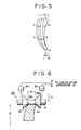
- the controller 20 reads the V-edge vertex information ( ⁇ i , ⁇ i , Z i ) and inputs the angular information ⁇ i into the pulse motor 14, then inputs the radius information ⁇ i into the pulse motor 22 and inputs Z-direction information Z i into the pulse motor 21 respectively in order to form the V-edge y in the lens L by a edging grinder G2 (see Fig. 5).
- the V-edge y is formed as such that the V-edge vertex is located in a position of a desired V-edge ratio 1 :m over the entire V-edge surface of the lens.
- the lens-edge thickness measuring apparatus 12 of the first embodiment is constructed such that the lens-edge thickness ⁇ i corresponding to the lens frame shape can be measured in the state where the lens L is uncut (before being subjected to rough grinding), the present invention is not limited to this.
- the lens-edge thickness ⁇ i of the lens after being subjected to rough grinding may be measured as shown in Fig. 6.
- a lens-edge thickness measuring apparatus 30 includes encoders 34 and 35, etc. for measuring the moving amounts of truncated cone shaped tops 32, 33 thrusted into a rod 31 abutted against the lens edge of the lens.
- the lens-edge thickness ⁇ i can be found by sandwiching the both ends of the lens edge of the lens L after the lens L is subjected to rough grinding between the shoulders 32a and 33a of the tops 32 and 33.
- the construction and operation of this lens-edge thickness measuring apparatus 30 are described in detail in the Japanese Patent Application No. Sho 58-225198 previously filed by the present applicant.
- the grinding method of the lens L is not necessarily a direct taking or grinding method in which the grinding is carried out based on the vector radius information of the lens frame which is measured beforehand. Instead, it may be performed by using a template which has pattern formed as same as the shape of the lens frame as in a conventional lens grinder.
- the template T as shown in the left-hand side of Fig. 2, is mounted on the end portion of the lens rotating axis 13 of the carriage C, and the stopper 23 is fixed to the height of the grooved bottom of the edging grinder G2.
- the V-edge vertex position information may be found as a set (Z i , ⁇ i ) with the angular information ⁇ i of the lens rotational axis.
- the lens-edge thickness is measuring over the entire circumference of the lens-edge of a lens to be ground, and the movement of the lens in the Z-axis direction is controlled in such a manner as to form a V-edge over the entire circumference at a desired V-edge ratio. Accordingly, even such a lens as having an aspherical refracting surface like a progressing multifocus lens can be put in a desired position.
Landscapes
- Engineering & Computer Science (AREA)
- Mechanical Engineering (AREA)
- Chemical & Material Sciences (AREA)
- Ceramic Engineering (AREA)
- Inorganic Chemistry (AREA)
- Grinding And Polishing Of Tertiary Curved Surfaces And Surfaces With Complex Shapes (AREA)
Applications Claiming Priority (2)
| Application Number | Priority Date | Filing Date | Title |
|---|---|---|---|
| JP9468/89 | 1989-01-18 | ||
| JP1009468A JPH07100288B2 (ja) | 1989-01-18 | 1989-01-18 | レンズ研削方法及びそのための装置 |
Publications (2)
| Publication Number | Publication Date |
|---|---|
| EP0379426A2 true EP0379426A2 (de) | 1990-07-25 |
| EP0379426A3 EP0379426A3 (de) | 1990-12-19 |
Family
ID=11721107
Family Applications (1)
| Application Number | Title | Priority Date | Filing Date |
|---|---|---|---|
| EP19900400126 Withdrawn EP0379426A3 (de) | 1989-01-18 | 1990-01-17 | Verfahren und Vorrichtung zum Schleifen einer Linse |
Country Status (2)
| Country | Link |
|---|---|
| EP (1) | EP0379426A3 (de) |
| JP (1) | JPH07100288B2 (de) |
Cited By (5)
| Publication number | Priority date | Publication date | Assignee | Title |
|---|---|---|---|---|
| WO1993013911A1 (de) * | 1992-01-13 | 1993-07-22 | Wernicke & Co. Gmbh | Vorrichtung zum facettieren von brillengläsern |
| EP0803325A3 (de) * | 1996-04-25 | 1998-01-14 | Wernicke & Co. GmbH | Verfahren zum Formschleifen des Umfangsrandes von Brillengläsern und gegebenenfalls anschliessenden Facettenschleifen sowie Brillenglasrand-Schleifmaschine |
| US6062947A (en) * | 1997-07-08 | 2000-05-16 | Nidek Co., Ltd. | Lens grinding apparatus |
| EP0899059A3 (de) * | 1997-08-29 | 2002-02-13 | Nidek Co., Ltd. | Brillenglas-Schleifmaschine |
| WO2006045965A1 (fr) * | 2004-10-28 | 2006-05-04 | Essilor International (Compagnie Generale D'optique) | Procede de finition ou de retouche de detourage de la peripherie d'une lentille ophtalmique selon un chant profile |
Families Citing this family (3)
| Publication number | Priority date | Publication date | Assignee | Title |
|---|---|---|---|---|
| FR2904703B1 (fr) * | 2006-08-04 | 2008-12-12 | Essilor Int | Paire de lunettes ophtalmiques et procede de formation d'une nervure peripherique d'emboitement sur le chant d'une lentille |
| JP6103788B1 (ja) * | 2016-04-15 | 2017-03-29 | 波田野 義行 | 眼鏡レンズ加工データ作成方法 |
| JP6124322B1 (ja) * | 2016-04-15 | 2017-05-10 | 波田野 義行 | 眼鏡レンズ加工データ作成方法 |
Family Cites Families (5)
| Publication number | Priority date | Publication date | Assignee | Title |
|---|---|---|---|---|
| FR2543039B1 (fr) * | 1983-03-22 | 1985-08-09 | Essilor Int | Procede pour le biseautage d'une lentille ophtalmique, et machine a meuler automatique correspondante |
| JPS60123259A (ja) * | 1983-12-02 | 1985-07-01 | Nippon Kogaku Kk <Nikon> | レンズ周縁加工機 |
| JPS629858A (ja) * | 1985-03-29 | 1987-01-17 | Tokyo Optical Co Ltd | レンズ研削装置 |
| JPS61274859A (ja) * | 1985-05-28 | 1986-12-05 | Tokyo Optical Co Ltd | レンズ研削装置 |
| EP0298129B1 (de) * | 1987-01-12 | 1993-11-03 | Hoya Corporation | Vorrichtung und verfahren zur behandlung des randes eines brillenglases |
-
1989
- 1989-01-18 JP JP1009468A patent/JPH07100288B2/ja not_active Expired - Lifetime
-
1990
- 1990-01-17 EP EP19900400126 patent/EP0379426A3/de not_active Withdrawn
Cited By (7)
| Publication number | Priority date | Publication date | Assignee | Title |
|---|---|---|---|---|
| WO1993013911A1 (de) * | 1992-01-13 | 1993-07-22 | Wernicke & Co. Gmbh | Vorrichtung zum facettieren von brillengläsern |
| EP0803325A3 (de) * | 1996-04-25 | 1998-01-14 | Wernicke & Co. GmbH | Verfahren zum Formschleifen des Umfangsrandes von Brillengläsern und gegebenenfalls anschliessenden Facettenschleifen sowie Brillenglasrand-Schleifmaschine |
| US6062947A (en) * | 1997-07-08 | 2000-05-16 | Nidek Co., Ltd. | Lens grinding apparatus |
| EP0890414A3 (de) * | 1997-07-08 | 2002-02-13 | Nidek Co., Ltd. | Linsenschleifvorrichtung |
| EP0899059A3 (de) * | 1997-08-29 | 2002-02-13 | Nidek Co., Ltd. | Brillenglas-Schleifmaschine |
| WO2006045965A1 (fr) * | 2004-10-28 | 2006-05-04 | Essilor International (Compagnie Generale D'optique) | Procede de finition ou de retouche de detourage de la peripherie d'une lentille ophtalmique selon un chant profile |
| FR2877249A1 (fr) * | 2004-10-28 | 2006-05-05 | Xavier Carriou | Procede de meulage pour la retouche de verres pre tailles |
Also Published As
| Publication number | Publication date |
|---|---|
| EP0379426A3 (de) | 1990-12-19 |
| JPH07100288B2 (ja) | 1995-11-01 |
| JPH02190247A (ja) | 1990-07-26 |
Similar Documents
| Publication | Publication Date | Title |
|---|---|---|
| US5053971A (en) | Method and apparatus for edging an optical lens | |
| EP0857540B1 (de) | Linsenschleifgerät | |
| US6942542B2 (en) | Eyeglass lens processing apparatus | |
| KR101456301B1 (ko) | 안경 렌즈 가공 장치 | |
| US7611242B2 (en) | Method for centering a semifinished spectacle lens blank | |
| KR101516432B1 (ko) | 안경 렌즈 가공 장치 | |
| JPH0822497B2 (ja) | 処方めがねレンズを作成するための方法及び装置 | |
| JPH11309657A (ja) | 眼鏡レンズ加工装置 | |
| US6290569B1 (en) | Lens grinding apparatus | |
| KR101516434B1 (ko) | 안경 렌즈 가공 장치 | |
| US6733369B1 (en) | Method and apparatus for polishing or lapping an aspherical surface of a work piece | |
| US20030214058A1 (en) | Method for fitting a holding block to a semifinished ophthalmic lens blank | |
| EP0379426A2 (de) | Verfahren und Vorrichtung zum Schleifen einer Linse | |
| KR20080072583A (ko) | 안경 렌즈 가공 장치 | |
| JP3990104B2 (ja) | レンズ研削加工装置 | |
| AU654045B2 (en) | Lathe for generating ophthalmic products from blanks, and a method of operating the lathe | |
| US6220927B1 (en) | Lens grinding apparatus | |
| JP4611618B2 (ja) | 無接触読み取り段階を含む、眼鏡レンズの研削方法 | |
| US6382790B1 (en) | Method for producing a multifocal correction lens, and system for implementing same | |
| EP0857539B1 (de) | Linsenschleifgerät | |
| JP7721970B2 (ja) | ヤゲン形成データ設定装置、眼鏡レンズ加工装置及びヤゲン形成データ設定プログラム | |
| JP2957224B2 (ja) | 玉摺機の面取機構 | |
| US5154020A (en) | Spherical surface machining apparatus and transporting apparatus therefor | |
| US20040039546A1 (en) | Process for plotting the shape of a contour of a previously machined ophthalmic lens | |
| JP2582788B2 (ja) | 玉摺機 |
Legal Events
| Date | Code | Title | Description |
|---|---|---|---|
| PUAI | Public reference made under article 153(3) epc to a published international application that has entered the european phase |
Free format text: ORIGINAL CODE: 0009012 |
|
| AK | Designated contracting states |
Kind code of ref document: A2 Designated state(s): DE FR GB IT NL |
|
| PUAL | Search report despatched |
Free format text: ORIGINAL CODE: 0009013 |
|
| AK | Designated contracting states |
Kind code of ref document: A3 Designated state(s): DE FR GB IT NL |
|
| 17P | Request for examination filed |
Effective date: 19910528 |
|
| 17Q | First examination report despatched |
Effective date: 19921020 |
|
| STAA | Information on the status of an ep patent application or granted ep patent |
Free format text: STATUS: THE APPLICATION IS DEEMED TO BE WITHDRAWN |
|
| 18D | Application deemed to be withdrawn |
Effective date: 19940920 |