EP0379794A1 - Schnellentlüftender Ballon-Dilatationskatheter - Google Patents
Schnellentlüftender Ballon-Dilatationskatheter Download PDFInfo
- Publication number
- EP0379794A1 EP0379794A1 EP89312618A EP89312618A EP0379794A1 EP 0379794 A1 EP0379794 A1 EP 0379794A1 EP 89312618 A EP89312618 A EP 89312618A EP 89312618 A EP89312618 A EP 89312618A EP 0379794 A1 EP0379794 A1 EP 0379794A1
- Authority
- EP
- European Patent Office
- Prior art keywords
- balloon
- lumen
- catheter
- inflation
- shaft
- Prior art date
- Legal status (The legal status is an assumption and is not a legal conclusion. Google has not performed a legal analysis and makes no representation as to the accuracy of the status listed.)
- Ceased
Links
- 238000010926 purge Methods 0.000 title claims abstract description 16
- 239000007788 liquid Substances 0.000 claims abstract description 32
- 238000000034 method Methods 0.000 claims description 10
- 238000004891 communication Methods 0.000 claims description 5
- 239000012530 fluid Substances 0.000 abstract description 6
- 210000001367 artery Anatomy 0.000 description 6
- 238000010276 construction Methods 0.000 description 4
- 238000002399 angioplasty Methods 0.000 description 3
- 238000001125 extrusion Methods 0.000 description 3
- 239000000463 material Substances 0.000 description 3
- 239000004033 plastic Substances 0.000 description 3
- 229920003023 plastic Polymers 0.000 description 3
- 230000007704 transition Effects 0.000 description 3
- 229920002633 Kraton (polymer) Polymers 0.000 description 2
- 208000031481 Pathologic Constriction Diseases 0.000 description 2
- 238000013459 approach Methods 0.000 description 2
- 210000004351 coronary vessel Anatomy 0.000 description 2
- 229920001903 high density polyethylene Polymers 0.000 description 2
- 239000004700 high-density polyethylene Substances 0.000 description 2
- 239000003550 marker Substances 0.000 description 2
- -1 polyethylene Polymers 0.000 description 2
- 238000002360 preparation method Methods 0.000 description 2
- 230000036262 stenosis Effects 0.000 description 2
- 208000037804 stenosis Diseases 0.000 description 2
- 238000013022 venting Methods 0.000 description 2
- 206010001526 Air embolism Diseases 0.000 description 1
- 229920001651 Cyanoacrylate Polymers 0.000 description 1
- MWCLLHOVUTZFKS-UHFFFAOYSA-N Methyl cyanoacrylate Chemical compound COC(=O)C(=C)C#N MWCLLHOVUTZFKS-UHFFFAOYSA-N 0.000 description 1
- 239000004698 Polyethylene Substances 0.000 description 1
- 239000000853 adhesive Substances 0.000 description 1
- 230000001070 adhesive effect Effects 0.000 description 1
- 230000005540 biological transmission Effects 0.000 description 1
- 150000001875 compounds Chemical class 0.000 description 1
- 238000007887 coronary angioplasty Methods 0.000 description 1
- 238000005336 cracking Methods 0.000 description 1
- 238000011161 development Methods 0.000 description 1
- 230000000916 dilatatory effect Effects 0.000 description 1
- 230000003467 diminishing effect Effects 0.000 description 1
- 230000000694 effects Effects 0.000 description 1
- 238000002347 injection Methods 0.000 description 1
- 239000007924 injection Substances 0.000 description 1
- 229920001684 low density polyethylene Polymers 0.000 description 1
- 239000004702 low-density polyethylene Substances 0.000 description 1
- 229920002529 medical grade silicone Polymers 0.000 description 1
- 238000012986 modification Methods 0.000 description 1
- 230000004048 modification Effects 0.000 description 1
- 229920000573 polyethylene Polymers 0.000 description 1
- 229920000642 polymer Polymers 0.000 description 1
- 229920000915 polyvinyl chloride Polymers 0.000 description 1
- 239000004800 polyvinyl chloride Substances 0.000 description 1
- 230000000717 retained effect Effects 0.000 description 1
- 239000004945 silicone rubber Substances 0.000 description 1
- 229910001220 stainless steel Inorganic materials 0.000 description 1
- 239000010935 stainless steel Substances 0.000 description 1
- 239000000126 substance Substances 0.000 description 1
- 229920002725 thermoplastic elastomer Polymers 0.000 description 1
Images

Classifications
-
- A—HUMAN NECESSITIES
- A61—MEDICAL OR VETERINARY SCIENCE; HYGIENE
- A61M—DEVICES FOR INTRODUCING MEDIA INTO, OR ONTO, THE BODY; DEVICES FOR TRANSDUCING BODY MEDIA OR FOR TAKING MEDIA FROM THE BODY; DEVICES FOR PRODUCING OR ENDING SLEEP OR STUPOR
- A61M25/00—Catheters; Hollow probes
- A61M25/10—Balloon catheters
- A61M25/104—Balloon catheters used for angioplasty
-
- A—HUMAN NECESSITIES
- A61—MEDICAL OR VETERINARY SCIENCE; HYGIENE
- A61M—DEVICES FOR INTRODUCING MEDIA INTO, OR ONTO, THE BODY; DEVICES FOR TRANSDUCING BODY MEDIA OR FOR TAKING MEDIA FROM THE BODY; DEVICES FOR PRODUCING OR ENDING SLEEP OR STUPOR
- A61M25/00—Catheters; Hollow probes
- A61M25/10—Balloon catheters
- A61M2025/1043—Balloon catheters with special features or adapted for special applications
- A61M2025/1077—Balloon catheters with special features or adapted for special applications having a system for expelling the air out of the balloon before inflation and use
Definitions
- This invention relates to balloon dilatation catheters.
- Balloon dilatation catheters are used for a variety of procedures in which a body lumen or vessel is dilated.
- such catheters are used in angioplasty procedures in which a stenosed region of an artery, such as a coronary artery, is widened by inserting a deflated balloon into the stenosis and then inflating the balloon under pressure to enlarge forcibly the lumen through the artery.
- Such catheters typically have an elongate flexible shaft and a balloon mounted at the distal end of the shaft.
- the shaft has an inflation lumen that communicates from the proximal end of the catheter to the interior of the balloon at the distal end of the shaft.
- the catheter also has a main lumen that extends fully the length of the catheter shaft, terminating in a distal outlet at the distal tip of the shaft, beyond the balloon.
- the main lumen may be used to receive a guidewire as well as to provide fluid communication with the interior of the patient's artery to inject radiopaque dye into the artery to visualize it fluoroscopically or to monitor the pressure in the artery, distally of the stenosis.
- the balloon is inflated with a liquid which is radiopaque so that the configuration and action of the balloon may be monitored fluoroscopically during the angioplasty procedure.
- Use of an incompressible liquid as an inflation medium assures effective development and transmission of dilating forces to the balloon and to the stenosed region of the artery that is to be dilated.
- Part of the preparation of the catheter for use involves purging air from the balloon and the inflation lumen to minimize the compressibility of the balloon fluid system.
- a catheter first is evacuated by a syringe connected to the inflation lumen at the proximal end of the catheter. After air has been evacuated from the balloon, the inflation lumen and balloon are filled, by the syringe with inflation liquid.
- one or more bubbles of air will remain entrapped in the balloon and, in an effort to purge as much air from the system as possible, it is the common practice to fill the balloon while holding the catheter with its distal end hanging down to permit the air to rise through the inflation lumen to the proximal end of the catheter where it may escape to atmosphere from the vented proximal end of the inflation lumen. Most, but not all of the air can be removed by this procedure. Usually, a small bubble of air will remain in the system.
- U.S. Patent 4,323,071 discloses a dilatation catheter system in which a slender venting tube is passed through the inflation lumen and into the balloon. As inflation liquid is purged through the inflation lumen and into the balloon, air within the system is permitted to escape through the vent tube. After the system has been completely filled with inflation liquid and the air has been vented, the vent tube may be removed or sealed within the inflation lumen.
- This system for purging air from the catheter is somewhat time consuming and may be awkward in that it requires a number of manipulations of the vent tube. Additionally, there is some risk that the vent tube may damage the balloon.
- a further difficulty is that if a minute drop of liquid contacts the distal tip of the vent tube before purging is completed, the tube will become blocked by capillary action and may have to be replaced.
- U.S. Patent 4,684,363 to Ari discloses a balloon dilatation catheter having a pair of parallel inflation lumens both of which extend from the proximal end of the catheter through the catheter shaft into communication with the interior of the balloon.
- the catheter is filled with inflation liquid by directing the liquid through one of the inflation lumens into the balloon while permitting the other lumen to vent to the atmosphere to permit air to escape.
- both of the lumens are connected to the inflation/deflation device and are operated in parallel to inflate or deflate the balloon.
- This approach requires the use of an additional lumen which necessarily requires either that the catheter be increased in outer diameter or that the other lumens in the catheter be smaller in size, thereby diminishing their capacity. Additionally, such a three lumen catheter is more difficult to extrude particularly in the smaller sizes of such catheters.
- U.S. Patent 4,692,200 Another approach for venting the balloon is disclosed in U.S. Patent 4,692,200 in which a very small air vent passage is formed between the catheter shaft and the distal end of the balloon where the balloon is mounted to the shaft.
- the vent passage is small enough to permit slow leakage of air out of the balloon as inflation liquid is pumped into the balloon system but is too small to permit an undue amount of liquid to leak through the vent in the operating range of most pressures.
- the disadvantages of this purging arrangement is that it presents some risk to the patient in that before the catheter is inserted into the patient, it is deflated by aspirating through the inflation lumen. Typically, there is some delay from the time that the catheter is aspirated until the time it is actually inserted into the patient.
- air may be drawn into the balloon through the vent.
- the inflation pressure may drive the air out through the vent and into the patient's coronary artery, thus presenting a risk of an air embolism. Additionally, the very small vent results in a relatively slow purging procedure.
- the balloon dilatation catheter includes an elongate flexible shaft having a balloon mounted at the distal end of the shaft.
- the shaft includes a main guidewire lumen that extends through the shaft from the proximal end of the catheter to an outlet at the distal tip.
- the shaft also includes an inflation/deflation lumen that extends from the proximal end of the shaft and communicates with the interior of the balloon.
- the portion of the shaft within the balloon is formed with a passageway through the shaft wall, such as a slit, to communicate the main lumen with the interior of the balloon.
- the passageway is part of a one-way valve means which permits liquid flow from the main lumen into the balloon under a predetermined pressure and precludes reverse flow at all operating pressure levels, from about one atmosphere negative pressure to as much as twenty atmospheres or more positive pressure.
- Another object of the invention is to provide a balloon dilatation catheter having a rapid purge system which does not require additional lumens.
- Another object of the invention is to provide a balloon dilatation catheter having an inflation lumen and a guidewire lumen and a one-way valve communicating the guidewire lumen with the interior of the balloon.
- a further object of the invention is to provide a balloon dilatation catheter that can be purged rapidly of air and which also provides a low balloon profile.
- one type of construction of the balloon dilatation catheter includes an elongate flexible shaft 10 that may be formed, as by extrusion, from an appropriate plastic material such as polyvinyl chloride, polyethylene or the like.
- a balloon dilatation catheter suitable for percutaneous transluminal coronary angioplasty may be of the order of 150 cm long and of the order of 0.045" outer diameter.
- the catheter shaft 10 has two lumens, including a main lumen 12 that extends the full length of the shaft and is open at the distal tip of the shaft at an outlet orifice 14 and an inflation/deflation lumen 16 that extends through the shaft from the proximal end to an opening 18 that communicates with the interior of the balloon 20.
- the distal opening 18 of the inflation lumen 16 preferably is located at the proximal end of the interior of the balloon and may be formed by skiving off the inflation lumen portion of the two lumen extrusion, leaving a single lumen tubular segment 19 distally of the opening 18.
- the tubular segment 19 of the shaft 10 terminates within the balloon 20 and the main lumen 12 is continued through the balloon and to the distal outlet 14 of the catheter by a single lumen tip tube 21 which may be formed from the same plastic material as the catheter shaft 10.
- the tubular segment 19 may have an outer diameter of .028" and an inner diameter, for the guidewire lumen, of .022".
- the tip tube 21 can be adhesively attached or fused to the distal end of the tubular segment 19.
- a highly radiopaque marker band 23 preferably is captured between the overlap of the tip tube 21 and the tubular segment 19.
- the tip tube 21 may have an outer diameter of the order of .027" and a wall thickness of about .0035".
- the proximal end of the two lumen extrusion includes a molded transition member 22 to which the distal ends of a pair of extension tubes 24, 26 are embedded.
- the extension tubes 24, 26 communicate, respectively, with the main lumen 12 and inflation lumen 16.
- Luer fittings 28, 30 are mounted on the proximal ends of the tubes 24, 26 for connection with appropriate fluid delivery communication devices such as inflation syringe, pressure measuring device and the like.
- the dilatation balloon 20 may be formed from a polymeric material adapted to be formed into a thin wall, highly flexible and relatively inelastic balloon.
- the balloon may be formed as described in U.S. Patent 4,490,421 to Levy.
- the balloon includes a central cylindrical section 32 and a pair of end cones 34, 36 and mounting collars 38, 40 by which the balloon 20 is mounted to the shaft 10.
- a flow passage 42 is formed through the wall of the tubular segment 19 of the catheter shaft within the balloon 20 to communicate the main lumen 12 with the interior of the balloon 20.
- the flow passage preferably is in the form of a slit 42, although it may also take the form of a small hole.
- An elastomeric sleeve 44 is mounted on the tubular segment 19 of the shaft within the balloon to cover the slit 42 and cooperate with the slit 42 to form a one-way valving arrangement, designated generally by reference character 41, which permits liquid to flow from the main lumen 12 into the balloon 20 but prevents reverse fluid flow.
- the slit 42 is formed through the wall of the tubular segment 19 and may be of the order of 1 mm long. Alternately, a small hole of the order of .010" diameter may be formed.
- the elastomeric sleeve 44 preferably is formed from a thermoplastic rubber polymer compound of ethylene butylene styrene available from the Shell Chemical Company under the trade designation Kraton, having a durometer of Shore A 63.
- the sleeve 44 preferably is of the order of .005" wall thickness and has an inner diameter such that it will form an interference fit about the tubular segment 19.
- the degree of interference fit should be selected with reference to the durometer of the elastomeric sleeve 44 and the stiffness of the tubular segment 19 and should be such that the sleeve imparts a constriction about the segment to insure that the sleeve 44 will be retained in place, covering the flow passage 42.
- an elastomeric sleeve 44 formed from Kraton may have a relaxed inner diameter of about .018" and a wall thickness of about .005".
- the sleeve 44 is expanded and is then placed on the tubular segment 19 while in an expanded confiquration.
- the expansion may be effected by immersing the sleeve in Freon which will cause it to expand sufficiently that it may be placed on the tubular segment 19. As the Freon evaporates and the sleeve warms to ambient temperature, it will tend to return to its original diameter and will thereby be securely constricted about the tubular segment 19, covering-the flow passage 42.
- the sleeve 44 should maintain a seal about the flow passage when the balloon is aspirated to about one atmosphere, as will be described.
- the sleeve 44 may be several millimeters long, an 9 mm length having been found to be satisfactory.
- the distal end of the sleeve 44 may overlap the proximal end of the tip tube.
- the sleeve 44 may be formed from a medical grade silicone rubber tubing, Shore A 70 durometer, having an inner diameter of about .018", a wall thickness of about .009" and being about 9 mm in length. Such a sleeve similarly is expanded and placed on the tubular segment 19 in its expanded configuration and then permitted to contract about the tubular segment.
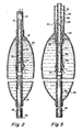
- FIG. 5 illustrates another catheter construction embodying the invention.
- the catheter is coaxial in which the shaft 50 is formed from an elongate inner tube 52 and an outer tube 54 both of which may be formed from high density polyethylene.
- a tip tube 56 which may be formed from low density polyethylene is attached to and may be heat fused to the distal end of the inner tube 52 and protrudes distally beyond the distal end of the outer tube 54.
- An annular support ring 55 may be formed from a heat bondable plastic such as high density polyethylene and is disposed between the end of the outer tube 54 and the inner tube 52. The ring is heat bonded to the inner and outer tubes 52, 54. The ring 55 maintains the concentricity of the tubes.
- a highly radiopaque marker band 57 preferably is interposed between the overlapping portions of the tip tube and inner tube.
- the distal end of the tip tube terminates in a distal outlet 61.
- a balloon 58 is mounted to the distal end of the catheter, its proximal end being adhesively attached to the distal end of the outer tube 54 and the distal end of the balloon being adhesively attached to the distal end of the tip tube 56 by an appropriate adhesive such as cyanoacrylate.
- the annular space between the inner and outer tubes 52, 54 defines an inflation lumen 60 by which the balloon is inflated and deflated.
- a plurality of circumferentially spaced apertures 63 are formed in the outer tube 54 proximally of the ring 55 to communicate the inflation lumen 60 with the interior of the balloon.
- a transition member similar to the transition member 22 of FIG. 1 is mounted to the proximal end of the catheter shaft and provides a means for communicating with the guidewire lumen 59 and the inflation lumen 60.
- an opening 42 such as a slit, is formed in the inner tube within the balloon and an elastomeric sleeve 44 is mounted on the tube over the opening as described above. The distal end of the sleeve may overlap the proximal end of the tip tube.
- the catheters of both FIGS. 1 and 5 are used in conjunction with a plug 46 which may be in the form of an elongate stylet having a head 48 at one end.
- the plug may be formed from stainless steel and is adapted to be inserted into the distal end of the guidewire lumen 12 to block that lumen.
- the plug is of a length shorter than the distance between the distal tip outlet 14 and the elastomeric sleeve 44.
- the plug 46 is used to temporarily obstruct the distal end of the guidewire lumen 12 while the catheter is being purged.
- the distal plug 46 When setting up the catheter in preparation for an angioplasty procedure, the distal plug 46 is inserted into the guidewire lumen through the distal outlet orifice 14. While maintaining the inflation lumen 16 vented to the atmosphere through tube 26, the catheter preferably is held with the distal end pointing down as indicated in FIGS. 2 and 5 so that air in the balloon may rise to the proximal end of the balloon and be in communication with the opening 18 to the inflation lumen (FIG. 2) or openings 63 to the inflation lumen 60 (FIG. 5). Then, contrast liquid is injected, as by a syringe, into the main lumen 12 via proximal tube 24. Air in the main lumen 12 will escape through the one-way valve 41 and inflation lumen 16.
- inflation liquid As inflation liquid is pumped into the system, it will flow, under a predetermined pressure, through the opening 42 and between the sleeve 44 and the outer surface of the tubular segment 19 (FIG. 2) or inner tube 52 (FIG. 5) into the interior of the balloon 20.
- the valve arrangement must have a cracking pressure greater than about 1 atm in order to assure that air will not leak into the device when the balloon is deflated, by aspiration, before inserting it into the patient.
- air As the system is filled progressively with inflation liquid, air is purged as it escapes through the inflation lumen 16. Continued injection of inflation liquid will cause the system to become fully filled with inflation liquid, all air having escaped.
- An inflation/deflation device then may be connected to the fitting 26 for the inflation lumen 16 and the distal plug 46 is removed, the catheter thus being ready to receive a guidewire for use in the dilatation procedure.
- the one-way valve arrangement 41 is such that it will prevent reverse flow of inflation liquid during the range of inflation pressures that may normally be expected to be encountered, for example, up to about 20 atm.
- an improved balloon dilatation catheter having a means for rapidly and easily purging air from the balloon and inflation lumen while filling the balloon and inflation lumen with inflation liquid in readiness for a dilatation procedure.
Landscapes
- Health & Medical Sciences (AREA)
- Heart & Thoracic Surgery (AREA)
- Life Sciences & Earth Sciences (AREA)
- Anesthesiology (AREA)
- Child & Adolescent Psychology (AREA)
- Biophysics (AREA)
- Pulmonology (AREA)
- Engineering & Computer Science (AREA)
- Vascular Medicine (AREA)
- Biomedical Technology (AREA)
- Hematology (AREA)
- Animal Behavior & Ethology (AREA)
- General Health & Medical Sciences (AREA)
- Public Health (AREA)
- Veterinary Medicine (AREA)
- Media Introduction/Drainage Providing Device (AREA)
Applications Claiming Priority (2)
| Application Number | Priority Date | Filing Date | Title |
|---|---|---|---|
| US30364789A | 1989-01-27 | 1989-01-27 | |
| US303647 | 1989-01-27 |
Publications (1)
| Publication Number | Publication Date |
|---|---|
| EP0379794A1 true EP0379794A1 (de) | 1990-08-01 |
Family
ID=23173072
Family Applications (1)
| Application Number | Title | Priority Date | Filing Date |
|---|---|---|---|
| EP89312618A Ceased EP0379794A1 (de) | 1989-01-27 | 1989-12-04 | Schnellentlüftender Ballon-Dilatationskatheter |
Country Status (4)
| Country | Link |
|---|---|
| EP (1) | EP0379794A1 (de) |
| JP (1) | JPH02283379A (de) |
| AU (1) | AU628444B2 (de) |
| CA (1) | CA2008642A1 (de) |
Cited By (11)
| Publication number | Priority date | Publication date | Assignee | Title |
|---|---|---|---|---|
| EP0696214A4 (de) * | 1993-04-26 | 1996-06-12 | Mallinckrodt Medical Inc | Verfahren zum verbinden von teilen eines inflationskatheters |
| EP0756876A1 (de) * | 1995-08-04 | 1997-02-05 | Nissho Corporation | Vaskulärer Dilatationskatheter |
| CN107875500A (zh) * | 2016-09-27 | 2018-04-06 | 先健科技(深圳)有限公司 | 球囊导管 |
| CN110251809A (zh) * | 2019-07-04 | 2019-09-20 | 江西三鑫医疗科技股份有限公司 | 一种球囊扩张导管 |
| CN112727001A (zh) * | 2020-12-28 | 2021-04-30 | 南京柯庆慕文化传媒有限公司 | 一种建筑发热地砖 |
| CN113995944A (zh) * | 2021-10-29 | 2022-02-01 | 南京康友医疗科技有限公司 | 一种球囊导引导管 |
| EP3970782A4 (de) * | 2019-06-06 | 2022-07-06 | Piedmont Medsystems (Zhuhai) Co., Ltd. | Ballonkatheter |
| CN115279445A (zh) * | 2019-10-08 | 2022-11-01 | 美敦力公司 | 准备用于心脏和血管介入治疗的球囊可膨胀导管的方法 |
| US11622781B2 (en) | 2020-01-30 | 2023-04-11 | Julier Medical AG | Apparatus and method for neurovascular endoluminal intervention |
| CN116570822A (zh) * | 2022-02-01 | 2023-08-11 | 艾柯医疗器械(北京)股份有限公司 | 多腔球囊导引导管装置和使用方法 |
| US11737767B2 (en) | 2022-01-21 | 2023-08-29 | Julier Medical AG | Neurovascular catheter and method of use |
Families Citing this family (6)
| Publication number | Priority date | Publication date | Assignee | Title |
|---|---|---|---|---|
| US6179856B1 (en) | 1989-07-05 | 2001-01-30 | Medtronic Ave, Inc. | Coaxial PTCA catheter with anchor joint |
| JP2003275213A (ja) * | 2002-03-26 | 2003-09-30 | Senko Medical Instr Mfg Co Ltd | 経食道超音波エコー診断装置及びバルーンカテーテル |
| WO2008114483A1 (ja) * | 2007-03-16 | 2008-09-25 | Olympus Terumo Biomaterials Corp. | 椎体圧迫骨折整復ユニット |
| WO2009084109A1 (ja) * | 2007-12-28 | 2009-07-09 | Olympus Terumo Biomaterials Corp. | 椎体圧迫骨折整復ユニット |
| US20120220902A1 (en) * | 2009-11-20 | 2012-08-30 | Sumitomo Bakelite Co., Ltd. | Inner diameter measurement instrument and priming method therefor |
| CN113018654B (zh) * | 2021-02-25 | 2022-11-15 | 四川大学华西医院 | 一种具有逐渐增加扩径的自助式食管狭窄扩张器及方法 |
Citations (5)
| Publication number | Priority date | Publication date | Assignee | Title |
|---|---|---|---|---|
| US3402718A (en) * | 1965-08-12 | 1968-09-24 | George O. Doherty | Endotracheal tube with valved balloon having removable inflation means and balloon rupturing means associated therewith |
| US3726283A (en) * | 1971-10-07 | 1973-04-10 | Kendall & Co | Body-retained catheter |
| US3742960A (en) * | 1971-10-07 | 1973-07-03 | Kendall & Co | Deflatable retention catheter |
| US4411055A (en) * | 1980-05-19 | 1983-10-25 | Advanced Cardiovascular Systems, Inc. | Vascular guiding catheter assembly and vascular dilating catheter assembly and a combination thereof and methods for making the same |
| DE3625871A1 (de) * | 1986-07-31 | 1988-02-04 | Schubert Werner | Ballonkatheter |
Family Cites Families (1)
| Publication number | Priority date | Publication date | Assignee | Title |
|---|---|---|---|---|
| US3742055A (en) * | 1969-07-31 | 1973-06-26 | Colgate Palmolive Co | 3-amino-bicyclo{8 2.2.2{9 octan-2-ols |
-
1989
- 1989-12-04 EP EP89312618A patent/EP0379794A1/de not_active Ceased
- 1989-12-14 AU AU46795/89A patent/AU628444B2/en not_active Expired - Fee Related
-
1990
- 1990-01-26 CA CA 2008642 patent/CA2008642A1/en not_active Abandoned
- 1990-01-29 JP JP2018798A patent/JPH02283379A/ja active Pending
Patent Citations (5)
| Publication number | Priority date | Publication date | Assignee | Title |
|---|---|---|---|---|
| US3402718A (en) * | 1965-08-12 | 1968-09-24 | George O. Doherty | Endotracheal tube with valved balloon having removable inflation means and balloon rupturing means associated therewith |
| US3726283A (en) * | 1971-10-07 | 1973-04-10 | Kendall & Co | Body-retained catheter |
| US3742960A (en) * | 1971-10-07 | 1973-07-03 | Kendall & Co | Deflatable retention catheter |
| US4411055A (en) * | 1980-05-19 | 1983-10-25 | Advanced Cardiovascular Systems, Inc. | Vascular guiding catheter assembly and vascular dilating catheter assembly and a combination thereof and methods for making the same |
| DE3625871A1 (de) * | 1986-07-31 | 1988-02-04 | Schubert Werner | Ballonkatheter |
Cited By (15)
| Publication number | Priority date | Publication date | Assignee | Title |
|---|---|---|---|---|
| EP0696214A4 (de) * | 1993-04-26 | 1996-06-12 | Mallinckrodt Medical Inc | Verfahren zum verbinden von teilen eines inflationskatheters |
| EP0756876A1 (de) * | 1995-08-04 | 1997-02-05 | Nissho Corporation | Vaskulärer Dilatationskatheter |
| CN107875500A (zh) * | 2016-09-27 | 2018-04-06 | 先健科技(深圳)有限公司 | 球囊导管 |
| EP3970782A4 (de) * | 2019-06-06 | 2022-07-06 | Piedmont Medsystems (Zhuhai) Co., Ltd. | Ballonkatheter |
| US12447318B2 (en) | 2019-06-06 | 2025-10-21 | Piedmont Medsystems (Zhuhai) Co., Ltd. | Balloon catheter |
| CN110251809A (zh) * | 2019-07-04 | 2019-09-20 | 江西三鑫医疗科技股份有限公司 | 一种球囊扩张导管 |
| CN115279445A (zh) * | 2019-10-08 | 2022-11-01 | 美敦力公司 | 准备用于心脏和血管介入治疗的球囊可膨胀导管的方法 |
| US11622781B2 (en) | 2020-01-30 | 2023-04-11 | Julier Medical AG | Apparatus and method for neurovascular endoluminal intervention |
| US11766272B2 (en) | 2020-01-30 | 2023-09-26 | Julier Medical AG | Apparatus and methods for neurovascular endoluminal intervention |
| US11911057B2 (en) | 2020-01-30 | 2024-02-27 | Julier Medical AG | Catheter apparatus and methods for endoluminal intervention |
| CN112727001A (zh) * | 2020-12-28 | 2021-04-30 | 南京柯庆慕文化传媒有限公司 | 一种建筑发热地砖 |
| CN113995944A (zh) * | 2021-10-29 | 2022-02-01 | 南京康友医疗科技有限公司 | 一种球囊导引导管 |
| US11737767B2 (en) | 2022-01-21 | 2023-08-29 | Julier Medical AG | Neurovascular catheter and method of use |
| US12004758B2 (en) | 2022-01-21 | 2024-06-11 | Julier Medical AG | Catheter for accessing the vasculature including the neurovasculature, and methods of use |
| CN116570822A (zh) * | 2022-02-01 | 2023-08-11 | 艾柯医疗器械(北京)股份有限公司 | 多腔球囊导引导管装置和使用方法 |
Also Published As
| Publication number | Publication date |
|---|---|
| AU4679589A (en) | 1990-08-02 |
| AU628444B2 (en) | 1992-09-17 |
| CA2008642A1 (en) | 1990-07-27 |
| JPH02283379A (ja) | 1990-11-20 |
Similar Documents
| Publication | Publication Date | Title |
|---|---|---|
| US5100385A (en) | Fast purge balloon dilatation catheter | |
| US5224933A (en) | Catheter purge device | |
| EP0379794A1 (de) | Schnellentlüftender Ballon-Dilatationskatheter | |
| US4638805A (en) | Self-venting balloon dilatation catheter and method | |
| US4702252A (en) | Catheters | |
| US5135486A (en) | Self-venting balloon dilitation catheter | |
| US4771777A (en) | Perfusion type balloon dilatation catheter, apparatus and method | |
| US4715378A (en) | Balloon catheter | |
| US5074845A (en) | Catheter with heat-fused balloon with waist | |
| US4771776A (en) | Dilatation catheter with angled balloon and method | |
| US5035705A (en) | Method of purging a balloon catheter | |
| US4909252A (en) | Perfusion balloon catheter | |
| US4606347A (en) | Inverted balloon catheter having sealed through lumen | |
| US4684363A (en) | Rapidly inflatable balloon catheter and method | |
| US4290428A (en) | Catheter with bulb | |
| US5085636A (en) | Balloon catheter with inflation-deflation valve | |
| US4692200A (en) | Self-venting balloon dilatation catheter and method | |
| US8177806B2 (en) | Dilation balloon having a valved opening and related catheters and methods | |
| EP0359489A2 (de) | Ausstülpbarer Ballon-Katheter mit einem Verankerungsring und Ballon dafür | |
| JPH0749057B2 (ja) | カテーテル | |
| US12226601B2 (en) | Balloon catheter assembly for insertion and positioning therapeutic devices within a vascular system | |
| EP0138974A1 (de) | Katheter vom umgekehrten ballontyp mit abgedichtetem durchsichtigem lumen. | |
| US4810455A (en) | Balloon catheter | |
| JPH0467991B2 (de) | ||
| US3467103A (en) | Inflatable bag catheter |
Legal Events
| Date | Code | Title | Description |
|---|---|---|---|
| PUAI | Public reference made under article 153(3) epc to a published international application that has entered the european phase |
Free format text: ORIGINAL CODE: 0009012 |
|
| AK | Designated contracting states |
Kind code of ref document: A1 Designated state(s): BE DE ES FR GB IT NL |
|
| 17P | Request for examination filed |
Effective date: 19910130 |
|
| RBV | Designated contracting states (corrected) |
Designated state(s): DE ES FR GB IT NL |
|
| 17Q | First examination report despatched |
Effective date: 19930713 |
|
| STAA | Information on the status of an ep patent application or granted ep patent |
Free format text: STATUS: THE APPLICATION HAS BEEN REFUSED |
|
| 18R | Application refused |
Effective date: 19950216 |