EP0379816A1 - Steuerung für Kreuzspuleninstrumente - Google Patents
Steuerung für Kreuzspuleninstrumente Download PDFInfo
- Publication number
- EP0379816A1 EP0379816A1 EP89403555A EP89403555A EP0379816A1 EP 0379816 A1 EP0379816 A1 EP 0379816A1 EP 89403555 A EP89403555 A EP 89403555A EP 89403555 A EP89403555 A EP 89403555A EP 0379816 A1 EP0379816 A1 EP 0379816A1
- Authority
- EP
- European Patent Office
- Prior art keywords
- control device
- logometer
- signal
- receives
- bits
- Prior art date
- Legal status (The legal status is an assumption and is not a legal conclusion. Google has not performed a legal analysis and makes no representation as to the accuracy of the status listed.)
- Granted
Links
Images



Classifications
-
- G—PHYSICS
- G01—MEASURING; TESTING
- G01D—MEASURING NOT SPECIALLY ADAPTED FOR A SPECIFIC VARIABLE; ARRANGEMENTS FOR MEASURING TWO OR MORE VARIABLES NOT COVERED IN A SINGLE OTHER SUBCLASS; TARIFF METERING APPARATUS; MEASURING OR TESTING NOT OTHERWISE PROVIDED FOR
- G01D3/00—Indicating or recording apparatus with provision for the special purposes referred to in the subgroups
- G01D3/02—Indicating or recording apparatus with provision for the special purposes referred to in the subgroups with provision for altering or correcting the law of variation
- G01D3/022—Indicating or recording apparatus with provision for the special purposes referred to in the subgroups with provision for altering or correcting the law of variation having an ideal characteristic, map or correction data stored in a digital memory
-
- G—PHYSICS
- G01—MEASURING; TESTING
- G01P—MEASURING LINEAR OR ANGULAR SPEED, ACCELERATION, DECELERATION, OR SHOCK; INDICATING PRESENCE, ABSENCE, OR DIRECTION, OF MOVEMENT
- G01P3/00—Measuring linear or angular speed; Measuring differences of linear or angular speeds
- G01P3/42—Devices characterised by the use of electric or magnetic means
- G01P3/44—Devices characterised by the use of electric or magnetic means for measuring angular speed
- G01P3/48—Devices characterised by the use of electric or magnetic means for measuring angular speed by measuring frequency of generated current or voltage
- G01P3/481—Devices characterised by the use of electric or magnetic means for measuring angular speed by measuring frequency of generated current or voltage of pulse signals
- G01P3/489—Digital circuits therefor
-
- G—PHYSICS
- G01—MEASURING; TESTING
- G01R—MEASURING ELECTRIC VARIABLES; MEASURING MAGNETIC VARIABLES
- G01R7/00—Instruments capable of converting two or more currents or voltages into a single mechanical displacement
- G01R7/04—Instruments capable of converting two or more currents or voltages into a single mechanical displacement for forming a quotient
- G01R7/06—Instruments capable of converting two or more currents or voltages into a single mechanical displacement for forming a quotient moving-iron type
Definitions
- the present invention relates to the field of logometers, that is to say devices comprising several crossed coils, preferably two coils crossed at 90 °, an axis guided in rotation, a magnet secured to the axis placed at the inside the coils, an indicator needle external to the coils and integral with the axis, and control means applying appropriate electrical signals to the coils.
- logometers also include a fixed cup containing a damping liquid, in which the magnet bathes.
- Each of the coils generates a magnetic field proportional to the current flowing through it.
- the magnet is positioned according to the result of these fields.
- the angle defined by the indicator needle, with respect to an original position is therefore determined by the relationship tan ⁇ 1 I1 / I2, in which I1 and I2 represent a value proportional to amperes- turns circulating in the coils respectively.
- logometers with large deflection are generally used to display a speed or the number of engine revolutions.
- Large deviation logometers generally include a return hairspring secured to the axis.
- the present invention relates more precisely to the control means designed to apply appropriate electrical signals to the coils of a logometer.
- the present invention now aims to provide new control means to improve the accuracy of logometers while being simple in structure and reasonably priced.
- Another object of the present invention is to provide control means for operating a 360 ° display.
- control means comprising means capable of generating a digital signal representative of the parameter to be displayed, memory means defining a coding of the digital signal on the basis of a predetermined law, of the sine, cosine or tangent type, the memory means being addressed by bits of intermediate weight of the digital signal and interpolation means able to correct the signal coming from the memory means, on the basis of the least significant bits of the digital signal.
- the abovementioned aims are achieved by means of logometer control using an input signal whose frequency is proportional to a parameter to be displayed, and for this purpose comprising a counter which receives on its counting input a fixed frequency clock signal, and on its control input a signal whose frequency is linked to the frequency of the input signal so that the counter counts the pulses of the clock signal during the period of the signal applied to its input control and a divider which divides a programmable constant by the signal from the counter so that there is at the output of the divider a digital signal representative of the frequency of the input signal.
- control comprising a module sensitive to the slope of the signal representative of the parameter to be displayed.
- control means essentially comprise an input stage 100 intended to generate a digital signal representative of the frequency of the input signal Fs, which frequency Fs is itself proportional to the parameter to be displayed, an intermediate processing stage 200, a coding stage 300 and an output stage 400.
- the input stage 100 comprises an input trigger module 110, a pre-divider module 120, a clock frequency divider module 130, a counter 140 working as a period meter and a programmable divider 150.
- the input signal whose frequency Fs represents the parameter to be displayed is applied to the trigger module 110.
- the trigger module 110 ensures in a manner known per se the shaping of the input signal in the form of logic slots of the same frequency Fs.
- the signal from the trigger module 110 is applied to the pre-divider module 120. This ensures a division of the input frequency Fs by a factor 2 A with an integer between 0 and 2 a -1, programmable by a inputs 122 of the unit 120.
- the division factor of 2 a can therefore take 2 has values.
- the signal obtained at the output of the predivisor 120 is at the frequency Fs / 2 A.
- the control means use a clock signal of fixed frequency Fo.
- This clock signal can be generated for example by a conventional crystal oscillator per se, not shown in the appended figures.
- the pilot clock signal from the divider 130 is applied to the counting input 142 of the counter 140.
- the counting periods of the counter 140 are determined by the signal from the predivisor 120, that is to say that the counter 140 counts the number C of pulses from the divider 130 at the frequency Fe between two consecutive edges of the same type , for example two rising edges, of the signal from the predivisor 120 at the frequency Fs / 2 A.
- the counter 140 therefore works as a period meter. It includes D bits, for example 20 bits; the passage to the high level of the most significant bit of the counter 140 determines that the frequency of the input signal is less than the minimum acceptable frequency.
- the digital value C presented at the output of the counter 140 is renewed on each active edge, for example each rising edge, of the signal from predivisor 120, and transferred to the divider 150 at each request thereof.
- the divider 150 divides a programmable constant E by the input quantity C coming from the counter 140. It provides the result G of the division E / C on its output 152.
- the constant E is programmed by e inputs of the divider 150, 6 inputs for example, so that for the maximum allowed value of the input frequency Fs, the division of E by the numerical value C corresponds to the maximum angle of deflection .
- the divider 150 supplies the signal G on H bits, for example on 10 bits.
- the number H of bits at the output of the divider 150 is determined by H> log (360 / I) / log2, a relationship in which I represents the desired display resolution.
- the capacity of the counter 140, and therefore the number of bits D at the output thereof are chosen as a function of the clock frequency Fe and the minimum admissible frequency.
- the number a of predivisor bits 120 which determines the largest predivision factor 2 (2a - 1) is chosen according to the range of input frequencies to be processed.
- the predivision factor 2 A is chosen in the prediviser 120 so that there is always 2 H + 1 ⁇ Cmin ⁇ 2 H + 2 , that is 2048 ⁇ Cmin ⁇ 4096 according to the above example.
- the minimum frequency of the input signal Fs acceptable as a function of the predivision factor 2 A corresponds to the maximum measurable period determined by the activation of the Dth bit of the counter 140.
- a digital signal on H bits is obtained at the output of the divider 150 which is proportional to the frequency of the input signal and to the desired deflection angle of the logometer.
- the signal obtained at the output of the programmable divider 150 is directed to the processing stage 200.
- the latter includes a module 210 which establishes a sliding average over K bits and a module 250 slope limiter.
- the module 210 for this purpose comprises K registers 212, 214, 216 and 218, 2 pointers 220, 222 and an adder / subtractor 230.
- the signals from the divider 150 output are successively introduced into the registers 212, 214, 216, 218.
- the pointer 220 contains the address of register 212 to 218 having received the last signal from the divider 150.
- the pointer 222 on the contrary contains the address of register 212 to 218 having received the first a signal from the divider 150.
- the adder / subtractor 130 contains a number equal to the sum of the contents of the K registers 212 to 218.
- the adder / subtractor 230 contains H + 2 bits, or 12 bits in the above example where the divider 150 provides its signal on 10 bits.
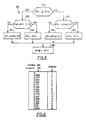
- this module 250 is to limit the slope of the signal. It proceeds as indicated in FIG. 5 by comparing the average value, that is to say AFm supplied at a given instant at the output of module 210 to the previous corresponding value, which will be called AFmp.
- This AFmp value is therefore stored in an appropriate register or memory cell.
- the module 250 provides an AFs signal at its output.
- step 252 the module 250 determines that AFm ⁇ AFmp the slope of the signal increases, we go to step 254 or during which the module 250 compares the difference (AFm - AFmp) to a predetermined threshold D1.
- step 254 If on the other hand the module 250 determines in step 254 that AFm - AFmp ⁇ D1, we go to step 258 which makes the signal Afs equal to AFm.
- step 252 the module 250 determines that AFm ⁇ AFmp, the slope of the signal decreases, we go to step 260 during which the module 250 compares the difference (AFmp - AFm) to a predetermined threshold D2.
- AFmp - AFm the decreasing slope of the signal exceeds the authorized threshold D2
- step 260 determines in step 260 that AFmp - AFM ⁇ D2
- step 264 makes the signal AFs equal to AFm.
- step 266 the previous average value stored AFmp is refreshed to the new value AFs.
- This value is directed to the coding module 300.
- This module 300 comprises memory means 310 and an interpolator 350.
- the memory means 310 are preferably formed from a ROM, they can however be formed from any functionally equivalent means, for example a structure known under the name PLA and described in particular in "Integrated Circuit Engineering - Glaser and Subak - Sharpe, Addison - Wesley p 726", or even a combinatorial logical structure with doors.
- the value of AFs is supplied to the output of the module 250 on R bits, for example 10 bits and applied to the coding stage 300.
- the memory means 310 contain 2 r1 M-bit words representing the sin values [90 ° x N] / 2 r1 with N integer between 1 and 2 r1 .
- the logometer comprises two coils crossed at 90 °, referenced B1 and B2, intended to receive signals of sine and cosine type respectively.
- the means 310 are associated with a pointing logic controlled by the two most significant bits SQ (1), SQ (O) coming from the module 250.
- the pointing logic reads the value contained at the address N if the penultimate most significant bit, SQ (O) is at O; on the other hand, it reads the value contained at the address (2 r1 - N) if the penultimate most significant bit SQ (O) is at 1;
- the pointing logic reads the value contained at the address (2 r1 - N) if the penultimate reads the highest weight SQ (O) is at O; on the other hand, it reads the value contained at the address N if the penultimate most significant bit SQ (O) is at 1.
- the signals representing the sines and cosines, coming from the interpolation module 350, are applied to the output stage 400.
- This comprises two modules 410, 420 which will determine duty cycles linked to the signals applied to the input of stage 400, and a logic output module 450.
- the modules 410, 420 are formed of up-down registers. Periodically, at period T Rc , the signals from the interpolator 350 are loaded respectively into these registers 410, 420. These are decremented with a fixed frequency Fdec.
- the exit 412, 422, of modules 410, 420 is at the high logic level as long as the content of the down-count registers has not gone down to O.
- the output 412, 422 of modules 410, 420 on the other hand indicates by a low logic state if the return at zero of the counter has been achieved.
- Logic signals are therefore obtained on the outputs 412, 422 of the modules 410 and 420, the duration of which at the high level is proportional to the sines and cosines respectively of the angle of deviation sought.
- the purpose of the output logic block 450 is to control the power stages supplying the coils of the logometer.
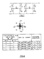
- these stages can be formed of 8 transistors To to T7 connected in pairs with their main conduction path between a supply terminal + Vcc and the ground.
- the two coils B1 and B2 are connected between the points common to pairs of transistors To, T4; T1, T5; T2, T6; T3, T7 associated.
- the output logic block 450 receives, on the one hand, the two most significant bits SQ (1) and SE (O) of the signal from the slope limiter module 250, on the other hand the signals Rcs and Rcc from modules 410, 420.
- the output logic block 450 will determine the direction of the currents passing through the coils B1 and B2 as a function of the required quadrant identified by the two most significant bits SQ (1) and SQ (O) coming from the module 250.
- the block 450 will impose the passage of the current be B10 to B11 and from B20 to B21 according to the representation of FIG. 7 and render for this conductors the transistors T1, T4, T3, T6.
- the block 450 will impose the passage of the current from B21 to B11 and from B21 to B20 and make the transistors conductive T1, T4, T2 and T7.
- the block 450 will impose the passage of the current from B11 to B10 and from B21 to B20 and make the conductors transistors T0, T5, T2 and T7.
- block 450 will impose the passage of current from B11 to B10 and from B20 to B21 and render conductors the transistors T0, T5 and T3, T6.
- the modules of the currents crossing the coils are given by the temporal modulation of a current Io, crossing the conducting transistors, by the signals Rcs and Rcc coming from the modules 410, 420, which are applied in an appropriate order on the bases or triggers G0 to G7 transistors.
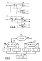
- the output logic block 450 can take the form shown in the attached FIG. 9.
- the module 450 comprises an exclusive OR gate 452 with two inputs, two inverters 454, 456, 4 AND doors 458, 462, 466, 470 with two inputs and four OR doors with 2 inputs including one inverting input.
- the signal from the module 410 and representative of a sine is called RCs
- Rcc the signal from module 420 and representative of a cosine
- SQ (1) the most significant bit from module 250
- SQ (O) the next least significant bit from module 250.
- Gate 452 receives on its inputs the signals SQ (1) and SQ (O).
- the inverter 454 receives the signal SQ (1) as an input while the inverter 456 receives the signal SQ (O) as an input.
- gate 458 receive the signal Rcs and the signal from inverter 454.
- the output of gate 458 is connected to the gate G1 of transistor T1.
- the inverting input of gate 410 receives the signal Rcs while its non-inverting input receives the signal SQ (1).
- the output of gate 460 is connected to the gate G4 of transistor T4.
- gate 462 receive the signal Rcs and the signal SQ (1).
- the output of gate 462 is connected to the trigger Go of the transistor To.
- the inverting input of gate 464 receives the signal Rcs while its non-inverting input receives the signal from inverter 454.
- the output of gate 464 is connected to the gate G5 of transistor T5.
- gate 466 receives the signal Rcc and the signal from inverter 456.
- the output of gate 466 is connected to the gate G3 of transistor T3.
- the inverting input of gate 468 receives the signal Rcc while its non-inverting input is connected to the output of gate 452.
- the output of gate 468 is connected to the gate G6 of transistor T6.
- the inputs of gate 470 receive the signal Rcc and the signal from gate 452.
- the output of gate 470 is connected to the gate Q2 of transistor T2.
- the inverting input of gate 472 receives the signal Rcc while its non-inverting input receives the signal from inverter 456.
- the output of gate 472 is connected to the gate G7 of transistor T7.
- the timing of the control device is operated as illustrated schematically in Figure 10 attached.
- FLAGO is called the appearance of a validation signal at the output of counter 140 or predivisor 120, indicating that a value C is available at the output of counter 140
- FLAG1 is called the appearance of a validation signal at the output of the modules 410, 420 indicating that they are ready to receive new data from the coding stage 300.
- step 500 illustrates an initialization step.
- step 502 the system examines whether FLAGO is validated.
- steps 504 loading of the content C of the counter 140 in the divider 150
- 506 division operation E (e) / C in the module 150
- 508 progression of the sliding average in the module 210 .
- Step 508 is followed by step 510.
- step 502 is followed by step 510 if it is determined in step 502 that the signal FLAGO is not validated.
- step 510 the module 250 limits the slope of the signal as indicated above.
- step 510 is followed by step 512. This corresponds to the calculation of the sine and cosine in the coding step 300.
- Step 512 is followed by step 514. During this, the system examines whether the signal FLAG1 is validated.
- Step 516 is followed by step 502.
- step 514 determines that the signal FLAG1 is not validated, this step loops back on itself.
- the slope limiter module 250 operates an angular limitation. This is transformed into a limitation of the first derivative of the angle with respect to time (i.e. into an angular speed limitation) thanks to the insertion of the stop loop 514 in the branch containing the operation of limitation of slope.
- the module 210 establishing the sliding average can be placed before the programmable divider 150 and not after it.
- the module 210 establishing the sliding average can be replaced by a module generating a hysteresis effect, that is to say not taking into account the samples of the module which precedes it, which if the samples differ from the immediately prior samples of a predetermined threshold.
- Q is called the sample from the module (140 or 150) preceding the hysteresis module 210, and Qp the previous sample.
- the module 210 provides at its output a signal Qs.
- step 220 If in step 220, the module 210 determines that Q> Qp the slope of the signal increases, we go to step 222 during which the module 210 compares the difference Q - Qp to a predetermined threshold D3.
- step 222 If on the other hand the module 210 determines in step 222 that Q - Qp ⁇ D3, we pass to step 224 which makes the signal Qs equal to Qp.
- step 220 If in step 220, the module 210 determines Q ⁇ Qp the signal slope decreases, we go to step 228 during which the module 210 compares the difference Qp - Q to a predetermined threshold D4.
- step 230 If on the other hand the module 210 determines in step 230 that Qp - Q ⁇ D4, we go to step 230 which makes the signal Qs equal to Qp.
- step 234 the previous stored value Qp is refreshed to the new value Qs.
- This value is directed to module 250.
- the maximum deviation of 360 ° is coded in 8 octants of 45 ° by the 3 most significant bits from the module 250.
- the r1 - 1 bits of intermediate weight from the module 250 are used to address the means 310 and thus define a coarse value of the tangent of the deviation sought.
- the least significant r2 bits are used to refine the value of this tangent by interpolation as previously indicated.
- the functional operations corresponding to the modules 150, 210 in its hysteresis variant, 250 and 350 are carried out by digital processing.
- the values contained in the memory means 310 may not correspond strictly to a sine / cosine or tangent law, but be appreciably offset with respect to these theoretical laws, if corrections are necessary, for example depending characteristics of the logometer.
- the counter 140 at D bits, for example at 20 bits, counts the periods of the clock signal Fo / B coming from the divider 130. It is reset to zero by active edges, for example rising edges , of the signal from the predivisor 120. On these active edges, the content of the counter 140 is transferred to the divider 150.
- a counter 140 at X bits for example at 10 bits, with X ⁇ D
Landscapes
- Physics & Mathematics (AREA)
- General Physics & Mathematics (AREA)
- Engineering & Computer Science (AREA)
- Technology Law (AREA)
- Indication And Recording Devices For Special Purposes And Tariff Metering Devices (AREA)
- Measurement And Recording Of Electrical Phenomena And Electrical Characteristics Of The Living Body (AREA)
- Complex Calculations (AREA)
- Transmission And Conversion Of Sensor Element Output (AREA)
- Analogue/Digital Conversion (AREA)
- Feedback Control In General (AREA)
Applications Claiming Priority (6)
| Application Number | Priority Date | Filing Date | Title |
|---|---|---|---|
| FR8816758A FR2640743B1 (fr) | 1988-12-19 | 1988-12-19 | Dispositif perfectionne de commande de logometre |
| FR8816757A FR2640742B1 (fr) | 1988-12-19 | 1988-12-19 | Dispositif de commande de logometre comprenant des moyens perfectionnes generant un signal numerique representatif de la frequence du signal d'entree |
| FR8816759 | 1988-12-19 | ||
| FR8816757 | 1988-12-19 | ||
| FR8816759A FR2640744B1 (fr) | 1988-12-19 | 1988-12-19 | Dispositif de commande de logometre comprenant des moyens numeriques de memorisation de capacite limitee |
| FR8816758 | 1988-12-19 |
Publications (2)
| Publication Number | Publication Date |
|---|---|
| EP0379816A1 true EP0379816A1 (de) | 1990-08-01 |
| EP0379816B1 EP0379816B1 (de) | 1993-03-31 |
Family
ID=27251759
Family Applications (1)
| Application Number | Title | Priority Date | Filing Date |
|---|---|---|---|
| EP89403555A Expired - Lifetime EP0379816B1 (de) | 1988-12-19 | 1989-12-19 | Steuerung für Kreuzspuleninstrumente |
Country Status (4)
| Country | Link |
|---|---|
| US (1) | US5142412A (de) |
| EP (1) | EP0379816B1 (de) |
| DE (1) | DE68905794T2 (de) |
| ES (1) | ES2039916T3 (de) |
Cited By (2)
| Publication number | Priority date | Publication date | Assignee | Title |
|---|---|---|---|---|
| EP0505826A1 (de) * | 1991-03-26 | 1992-09-30 | Rohm Co., Ltd. | Ansteuerungsverfahren für Messinstrument |
| EP0588403A1 (de) * | 1992-09-14 | 1994-03-23 | Delco Electronics Corporation | Verfahren und Vorrichtung zur Steuerung eines Messinstrumentes |
Families Citing this family (6)
| Publication number | Priority date | Publication date | Assignee | Title |
|---|---|---|---|---|
| US5214597A (en) * | 1988-11-09 | 1993-05-25 | Yazaki Corporation | Cross coil type indicator |
| JP2543245B2 (ja) * | 1990-09-17 | 1996-10-16 | オ−クマ株式会社 | 位置検出誤差補正装置 |
| US6547139B1 (en) * | 1998-07-10 | 2003-04-15 | Welch Allyn Data Collection, Inc. | Method and apparatus for extending operating range of bar code scanner |
| US6021849A (en) * | 1998-11-30 | 2000-02-08 | Averhoff; Jon R. | Double acting gas displaced chamber lift system and method |
| US8634491B2 (en) | 2010-03-10 | 2014-01-21 | Rockstar Consortium USLP | Method and apparatus for reducing the contribution of noise to digitally sampled signals |
| JP6452210B1 (ja) * | 2017-09-12 | 2019-01-16 | Ckd日機電装株式会社 | 速度検出装置 |
Citations (6)
| Publication number | Priority date | Publication date | Assignee | Title |
|---|---|---|---|---|
| US3976860A (en) * | 1974-08-08 | 1976-08-24 | Teldix Gmbh | Method and arrangement for conversion of a digital measured value |
| US4070665A (en) * | 1976-05-27 | 1978-01-24 | The Singer Company | High accuracy digital to analog resolver converter |
| GB2045953A (en) * | 1979-03-22 | 1980-11-05 | Gen Motors Corp | Apparatus for driving a gauge |
| EP0218737A1 (de) * | 1984-09-18 | 1987-04-22 | VDO Adolf Schindling AG | Einrichtung zur Ansteuerung eines Kreuzspulenanzeigeinstruments |
| FR2596870A1 (fr) * | 1986-04-08 | 1987-10-09 | Bbc Brown Boveri & Cie | Procede de mesurage numerique pour l'affichage quasi analogique de valeurs mesurees et dispositif pour la mise en oeuvre de ce procede |
| EP0263305A2 (de) * | 1986-10-03 | 1988-04-13 | Robert Bosch Gmbh | Schaltungsanordnung zur Beeinflussung von Signalen |
Family Cites Families (12)
| Publication number | Priority date | Publication date | Assignee | Title |
|---|---|---|---|---|
| US3636447A (en) * | 1970-05-06 | 1972-01-18 | Gen Motors Corp | Wide-angle two-coil electrical gauge |
| US3946311A (en) * | 1973-06-11 | 1976-03-23 | Stewart-Warner Corporation | Air core gauge with expanded pointer range |
| US3868570A (en) * | 1973-09-28 | 1975-02-25 | Chrysler Corp | Electronic digital speedometer |
| GB1542843A (en) * | 1975-04-03 | 1979-03-28 | Solartron Electronic Group | Signal processor |
| US4051434A (en) * | 1976-05-28 | 1977-09-27 | General Motors Corporation | Digital frequency measuring circuitry |
| US4356445A (en) * | 1980-07-10 | 1982-10-26 | Cherry Semiconductor Corporation | Method and apparatus for driving air core meter movements |
| US4491007A (en) * | 1982-12-02 | 1985-01-01 | Beede Electrical Instrument Co., Inc. | Rangeable speedometer/odometer |
| US4553093A (en) * | 1983-03-08 | 1985-11-12 | Yazaki Sogyo Kabushiki Kaisha | Tachometer |
| US4742297A (en) * | 1985-07-08 | 1988-05-03 | Teleflex Incorporated | Programmable cycle meter |
| JPS6459162A (en) * | 1987-08-31 | 1989-03-06 | Japan Engine Valve Mfg | Cross coil type mobile magnet instrument |
| JPH0711538B2 (ja) * | 1988-02-05 | 1995-02-08 | ジェコー株式会社 | 交差コイル式計器の駆動回路 |
| US4939675A (en) * | 1988-12-22 | 1990-07-03 | Chrysler Corporation | Digital system for controlling mechanical instrument gauges |
-
1989
- 1989-12-19 ES ES198989403555T patent/ES2039916T3/es not_active Expired - Lifetime
- 1989-12-19 EP EP89403555A patent/EP0379816B1/de not_active Expired - Lifetime
- 1989-12-19 DE DE89403555T patent/DE68905794T2/de not_active Expired - Fee Related
- 1989-12-19 US US07/452,642 patent/US5142412A/en not_active Expired - Lifetime
Patent Citations (6)
| Publication number | Priority date | Publication date | Assignee | Title |
|---|---|---|---|---|
| US3976860A (en) * | 1974-08-08 | 1976-08-24 | Teldix Gmbh | Method and arrangement for conversion of a digital measured value |
| US4070665A (en) * | 1976-05-27 | 1978-01-24 | The Singer Company | High accuracy digital to analog resolver converter |
| GB2045953A (en) * | 1979-03-22 | 1980-11-05 | Gen Motors Corp | Apparatus for driving a gauge |
| EP0218737A1 (de) * | 1984-09-18 | 1987-04-22 | VDO Adolf Schindling AG | Einrichtung zur Ansteuerung eines Kreuzspulenanzeigeinstruments |
| FR2596870A1 (fr) * | 1986-04-08 | 1987-10-09 | Bbc Brown Boveri & Cie | Procede de mesurage numerique pour l'affichage quasi analogique de valeurs mesurees et dispositif pour la mise en oeuvre de ce procede |
| EP0263305A2 (de) * | 1986-10-03 | 1988-04-13 | Robert Bosch Gmbh | Schaltungsanordnung zur Beeinflussung von Signalen |
Cited By (3)
| Publication number | Priority date | Publication date | Assignee | Title |
|---|---|---|---|---|
| EP0505826A1 (de) * | 1991-03-26 | 1992-09-30 | Rohm Co., Ltd. | Ansteuerungsverfahren für Messinstrument |
| US5218291A (en) * | 1991-03-26 | 1993-06-08 | Rohm Co., Ltd. | Meter and meter driving system with indication fluctuation suppression and enhancement |
| EP0588403A1 (de) * | 1992-09-14 | 1994-03-23 | Delco Electronics Corporation | Verfahren und Vorrichtung zur Steuerung eines Messinstrumentes |
Also Published As
| Publication number | Publication date |
|---|---|
| EP0379816B1 (de) | 1993-03-31 |
| DE68905794T2 (de) | 1993-10-14 |
| DE68905794D1 (de) | 1993-05-06 |
| US5142412A (en) | 1992-08-25 |
| ES2039916T3 (es) | 1993-10-01 |
Similar Documents
| Publication | Publication Date | Title |
|---|---|---|
| FR2550644A1 (fr) | Dispositif de reglage manuel | |
| EP0379816B1 (de) | Steuerung für Kreuzspuleninstrumente | |
| FR2580819A1 (fr) | Systeme pour detecter la presence d'un signal pur dans un signal bruite discret mesure a taux moyen de bruit constant avec une probabilite de fausse detection inferieure a un taux de fausse detection predetermine. | |
| FR2689261A1 (fr) | Dispositif de commande destiné à asservir un objet à une position donnée. | |
| FR2498848A1 (fr) | Procede pour affaiblir un signal numerique et dispositif pour l'execution de ce procede | |
| EP0475862B1 (de) | Schneller Zähler/Teiler und dessen Verwendung in einem Zähler mit Impulsunterdrückung | |
| EP0071505B1 (de) | Verfahren und Einrichtung zur Abtastung eines sinusförmigen Signals durch ein Signal mit einem Vielfachen der Eingangsfrequenz | |
| JPS5939116A (ja) | ステツプ応答平均化フイルタ | |
| EP0476592A2 (de) | Adressengenerator für den Datenspeicher eines Prozessors | |
| FR2640744A1 (fr) | Dispositif de commande de logometre comprenant des moyens numeriques de memorisation de capacite limitee | |
| FR2640742A1 (fr) | Dispositif de commande de logometre comprenant des moyens perfectionnes generant un signal numerique representatif de la frequence du signal d'entree | |
| FR2640743A1 (fr) | Dispositif perfectionne de commande de logometre | |
| CA1244920A (fr) | Procede d'extension de la gamme des frequences des recurrences radar acceptables par un transformateur numerique d'images et moyens de mise en oeuvre de ce procede | |
| FR2617608A1 (fr) | Dispositif pour mesurer la frequence d'un signal sinusoidal produit par un generateur de signaux | |
| FR2584250A1 (fr) | Dispositif de traitement de signaux numeriques travaillant avec des trains de bits continus | |
| EP0621682B1 (de) | Einrichtung zur Frequenzteilung | |
| EP0192530B1 (de) | Anordnung zum Pulslängenvergleich zweier Rechteckpulse | |
| FR2469823A1 (fr) | Generateur de frequences asservi en temperature et synthetiseur de frequences comportant au moins un tel generateur | |
| EP0135428B1 (de) | Verfahren und Anordnung zum Bestimmen einer Geschwindigkeit | |
| JP2771910B2 (ja) | 計測回路 | |
| EP1209578B1 (de) | Vorrichtung zum erzeugen von wellenformdaten durch abgetastete funktionen | |
| EP0196255B1 (de) | Verfahren zur Erzeugung eines synchronen Taktsignals von einem einfachen oder doppelten dichtheitskodiertem Signal und Anordnung zur Durchführung des Verfahrens | |
| JPS6140049B2 (de) | ||
| EP0465334A1 (de) | Vorrichtung und Verfahren zum Filtern elektrischer Signale, insbesondere für die Ansteuerung von Kreuzspulanzeigeinstrumenten | |
| EP0592260B1 (de) | Zählschaltung für Frequenzteilung und Synthetisierer mit einer derartigen Schaltung |
Legal Events
| Date | Code | Title | Description |
|---|---|---|---|
| PUAI | Public reference made under article 153(3) epc to a published international application that has entered the european phase |
Free format text: ORIGINAL CODE: 0009012 |
|
| AK | Designated contracting states |
Kind code of ref document: A1 Designated state(s): DE ES GB IT SE |
|
| 17P | Request for examination filed |
Effective date: 19901015 |
|
| 17Q | First examination report despatched |
Effective date: 19910814 |
|
| GRAA | (expected) grant |
Free format text: ORIGINAL CODE: 0009210 |
|
| ITF | It: translation for a ep patent filed | ||
| AK | Designated contracting states |
Kind code of ref document: B1 Designated state(s): DE ES GB IT SE |
|
| PG25 | Lapsed in a contracting state [announced via postgrant information from national office to epo] |
Ref country code: SE Effective date: 19930331 Ref country code: GB Effective date: 19930331 |
|
| REF | Corresponds to: |
Ref document number: 68905794 Country of ref document: DE Date of ref document: 19930506 |
|
| REG | Reference to a national code |
Ref country code: ES Ref legal event code: FG2A Ref document number: 2039916 Country of ref document: ES Kind code of ref document: T3 |
|
| GBV | Gb: ep patent (uk) treated as always having been void in accordance with gb section 77(7)/1977 [no translation filed] |
Effective date: 19930331 |
|
| PLBE | No opposition filed within time limit |
Free format text: ORIGINAL CODE: 0009261 |
|
| STAA | Information on the status of an ep patent application or granted ep patent |
Free format text: STATUS: NO OPPOSITION FILED WITHIN TIME LIMIT |
|
| 26N | No opposition filed | ||
| ITTA | It: last paid annual fee | ||
| PGFP | Annual fee paid to national office [announced via postgrant information from national office to epo] |
Ref country code: DE Payment date: 20051207 Year of fee payment: 17 |
|
| PGFP | Annual fee paid to national office [announced via postgrant information from national office to epo] |
Ref country code: ES Payment date: 20051214 Year of fee payment: 17 |
|
| PGFP | Annual fee paid to national office [announced via postgrant information from national office to epo] |
Ref country code: IT Payment date: 20061231 Year of fee payment: 18 |
|
| PG25 | Lapsed in a contracting state [announced via postgrant information from national office to epo] |
Ref country code: DE Free format text: LAPSE BECAUSE OF NON-PAYMENT OF DUE FEES Effective date: 20070703 |
|
| REG | Reference to a national code |
Ref country code: ES Ref legal event code: FD2A Effective date: 20061220 |
|
| PG25 | Lapsed in a contracting state [announced via postgrant information from national office to epo] |
Ref country code: ES Free format text: LAPSE BECAUSE OF NON-PAYMENT OF DUE FEES Effective date: 20061220 |
|
| PG25 | Lapsed in a contracting state [announced via postgrant information from national office to epo] |
Ref country code: IT Free format text: LAPSE BECAUSE OF NON-PAYMENT OF DUE FEES Effective date: 20071219 |