EP0379931A2 - Embouchoir pour la fabrication de chaussures sur un trajet de transfert commandé par un ordinateur - Google Patents
Embouchoir pour la fabrication de chaussures sur un trajet de transfert commandé par un ordinateur Download PDFInfo
- Publication number
- EP0379931A2 EP0379931A2 EP90100804A EP90100804A EP0379931A2 EP 0379931 A2 EP0379931 A2 EP 0379931A2 EP 90100804 A EP90100804 A EP 90100804A EP 90100804 A EP90100804 A EP 90100804A EP 0379931 A2 EP0379931 A2 EP 0379931A2
- Authority
- EP
- European Patent Office
- Prior art keywords
- fork
- last
- strips according
- strip
- metal part
- Prior art date
- Legal status (The legal status is an assumption and is not a legal conclusion. Google has not performed a legal analysis and makes no representation as to the accuracy of the status listed.)
- Granted
Links
Images

Classifications
-
- A—HUMAN NECESSITIES
- A43—FOOTWEAR
- A43D—MACHINES, TOOLS, EQUIPMENT OR METHODS FOR MANUFACTURING OR REPAIRING FOOTWEAR
- A43D23/00—Single parts for pulling-over or lasting machines
- A43D23/02—Wipers; Sole-pressers; Last-supports; Pincers
- A43D23/025—Last-supports
-
- A—HUMAN NECESSITIES
- A43—FOOTWEAR
- A43D—MACHINES, TOOLS, EQUIPMENT OR METHODS FOR MANUFACTURING OR REPAIRING FOOTWEAR
- A43D3/00—Lasts
- A43D3/02—Lasts for making or repairing shoes
- A43D3/024—Lasts with a fore part and heel section relatively slideable to one another along an inclined line of cut
-
- A—HUMAN NECESSITIES
- A43—FOOTWEAR
- A43D—MACHINES, TOOLS, EQUIPMENT OR METHODS FOR MANUFACTURING OR REPAIRING FOOTWEAR
- A43D3/00—Lasts
- A43D3/02—Lasts for making or repairing shoes
- A43D3/027—Lasts with exchangeable parts, e.g. for changing the form or for remodelling
Definitions
- the invention relates to a production last for shoe manufacture on a computer-controlled transfer line which is equipped with robots and automatic processing machines, according to the preamble of claim 1.
- the sliding strips and the folding strips are currently used in shoe manufacturing: the sliding strips and the folding strips. These each have a toe part and a heel part, which are movably coupled to one another by means of a hinge.
- a spring built into the hinge ensures that the heel and toe parts are in a fixed position with respect to one another in the closed position of the last.
- the purpose of the hinge is to shorten the effective last length by the relative movement of the last parts so that the finished shoe can be finished.
- the strips In order to ensure a smooth process in such production lines, the strips must also be precisely positioned and adjustable. However, this is not possible with strips made of plastic, as they are often used, because these plastics tend to creep.
- the present invention is therefore based on the object of specifying a production strip suitable for use in computer-controlled transfer lines, which, with lower actuation forces, permits a greater shortening of the effective last length without overstretching the shoe, permits exact adjustment of the releasable connecting members and is adapted to a boot production without problems can be.
- the length of the elongated hole or the long groove which can be set as desired, in conjunction with the inclination of the cutting surface between the two strip parts, which can also be selected in principle, can result in a practically arbitrary reduction in the effective length of the strip, but that Actuating force itself can be chosen independently and adjusted solely by the strength of the spring and that the closure structure is simple, inexpensive and reliable.
- Lasts made of plastic are often used in the manufacture of shoes. If you screw the connecting elements, which are responsible for the detachable positioning of the last at the individual processing stations of the transfer line, to the plastic, they change their position uncontrollably due to the plastic properties. Malfunctions occur. However, this can be prevented if the last is further developed according to the features of claims 9 and 10, respectively.
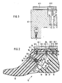
- a fabrication last 10 consisting of a tip part 11, a heel part 12 and a closure 20.
- the intersection between the two strip parts 11, 12 is identified by reference number 13.
- the tip part 11 of the last 10 has a vertical, recessed groove 15 in the area of the cut surface 13.
- a flat metal part 21 is fastened in this by means of screws 29.
- the flat metal part 21 has an elongated hole 22 which extends essentially parallel to the cutting surface 13.
- the elongated hole 22 has a latching groove 26 at its upper end, which effects the later closed position of the last 10.
- a stepped bore 14 is provided in the heel part 12 of the last 10. A fork 23 is guided in this.
- the fork 23 has a fork head 23.1, the two legs of which overlap the flat metal part 21.
- a cross pin 24 is mounted in the fork head 23.1, on which a roller 25 is rotatably fastened.
- the cross pin 24 with roller 25 extends through the elongated hole 22 and in this way holds the two strip parts 11, 12 together.
- the roller 25 runs along the wall of the elongated hole 22 when the two strip parts 11, 12 are moved against each other.
- the elongated hole 22 and the transverse pin 24 can be replaced by two elongated grooves, in each of which a transverse pin engages.
- the shaft 23.2 of the fork 23 carries a spiral spring 27 which is supported against a metal sleeve 28 screwed into the stepped bore 14.
- the spring 27 is designed as a compression spring.
- the locking groove 26 would have to be formed in the elongated hole 22 on the other side.
- the flat metal part 21 can also be spring-mounted.
- Elongated hole 22 and fork 23 are approximately perpendicular to each other. In this way, the force required to move the last parts 11, 12 is minimal after overcoming the locking position, but the holding force of the last parts 11, 12 against one another is maximal.
- FIG. 2 shows an embodiment in which the flat metal part 21 is mounted in the heel part 12, the fork 23 in the tip part 11 of the last 10.
- the advantage of this embodiment is that the shaft 23.2 of the fork 23 is accessible even when a shoe shaft is attached.
- a two-part mounting plate 30.1, 30.2 is fastened on the tip part 11 and the heel part 12 of the last 10.
- This receiving plate 30 is used for the detachable connection of the last 10 with the respective processing station of the transfer line.
- the receiving plate 30 In order to ensure that the transfer line runs smoothly, the receiving plate 30 must be positioned exactly. If, as is often the case, the last 10 is made of plastic, the required accuracy of the adjustment of the mounting plate 30 cannot be guaranteed in the long run, since the plastics used to produce the last 10 tend to creep. For this reason, a bore 31.1, 31.2 is made in the toe part 11 and the heel part 12 under the receiving plate 30 and parallel thereto.
- a metal part 32.1, 32.2 here in the form of a fine-thread rod, is inserted into each of these bores 31.
- the metal part 32.1, 32.2 has transverse threaded holes 34. Below the receiving plate 30 are in the area of the threaded holes 34 Connecting holes 35 are introduced with a relatively large cross section. The fastening screws 33.1, 33.2 are inserted through these and screwed into the threaded bores 34 of the metal parts 32.1, 32.2.
- Fig. 3 shows a boot construction as it is used when boots are to be produced on the transfer line instead of low shoes.
- the boot structure 40 consists of a metal body, preferably of aluminum. It is screwed to the last 10 instead of the mounting plate 30. A comparable mounting plate 41.1 is screwed onto its top. Since the boot structure 40 is made of metal, the adjustment of the mounting plate 41.1 to the boot structure 40 which has been set once remains unchanged.
- the rear part 41.2 of the mounting plate 41 is screwed to a connecting bolt 42.
- This is mounted so that it can move longitudinally in a bore in the boot structure 40.
- the connecting bolt 42 has a longitudinal slot 43 through which a cross pin 44 is inserted.
- a pivot bearing 45 can be seen, on which a connecting screw 46.2 then engages, which is screwed to the heel part 12 of the last 10.
- the strip 10 can be opened and closed via the rear part 41.2 of the mounting plate 41.
- the boot structure 40 is screwed to the tip part 11 of the last 10 by means of connecting screws 46.1.
Landscapes
- Footwear And Its Accessory, Manufacturing Method And Apparatuses (AREA)
- Control Of Conveyors (AREA)
- Multi-Process Working Machines And Systems (AREA)
- Electric Cable Installation (AREA)
- Injection Moulding Of Plastics Or The Like (AREA)
Applications Claiming Priority (2)
| Application Number | Priority Date | Filing Date | Title |
|---|---|---|---|
| DE8900722U | 1989-01-24 | ||
| DE8900722U DE8900722U1 (de) | 1989-01-24 | 1989-01-24 | Fabrikationsleisten für die Schuhfertigung |
Publications (3)
| Publication Number | Publication Date |
|---|---|
| EP0379931A2 true EP0379931A2 (fr) | 1990-08-01 |
| EP0379931A3 EP0379931A3 (fr) | 1992-01-15 |
| EP0379931B1 EP0379931B1 (fr) | 1994-12-21 |
Family
ID=6835309
Family Applications (1)
| Application Number | Title | Priority Date | Filing Date |
|---|---|---|---|
| EP90100804A Expired - Lifetime EP0379931B1 (fr) | 1989-01-24 | 1990-01-16 | Embouchoir pour la fabrication de chaussures sur un trajet de transfert commandé par un ordinateur |
Country Status (8)
| Country | Link |
|---|---|
| US (1) | US5054147A (fr) |
| EP (1) | EP0379931B1 (fr) |
| AT (1) | ATE115837T1 (fr) |
| DD (1) | DD291690A5 (fr) |
| DE (2) | DE8900722U1 (fr) |
| DK (1) | DK0379931T3 (fr) |
| ES (1) | ES2067571T3 (fr) |
| PT (1) | PT92927A (fr) |
Families Citing this family (9)
| Publication number | Priority date | Publication date | Assignee | Title |
|---|---|---|---|---|
| TW249196B (fr) * | 1993-07-23 | 1995-06-11 | James L Throneburg | |
| US5335517A (en) * | 1993-07-23 | 1994-08-09 | James L. Throneburg | Anatomical isotonic sock and method of knitting the same |
| USD374553S (en) | 1995-02-28 | 1996-10-15 | James L. Throneburg | Shoe last |
| US5881413A (en) * | 1995-02-28 | 1999-03-16 | James L. Throneburg | Shoe last and method of constructing a shoe |
| US5714098A (en) * | 1995-12-20 | 1998-02-03 | Nike, Inc. | Footwear fitting method |
| FR2832909B1 (fr) * | 2001-12-03 | 2004-04-02 | Actis Ets | Forme avec dispositif de prehension, pour la fabrication de chaussures |
| AUPS207602A0 (en) * | 2002-05-02 | 2002-06-06 | Blundstone Pty Limited | A last locking device |
| FR2854032B1 (fr) * | 2003-04-25 | 2005-05-27 | Actis Ets | Forme en plusieurs parties pour la fabrication de chaussures |
| CN108652133A (zh) * | 2017-03-27 | 2018-10-16 | 涂火龙鞋楦股份有限公司 | 运用于自动化工艺的鞋楦制作方法 |
Family Cites Families (16)
| Publication number | Priority date | Publication date | Assignee | Title |
|---|---|---|---|---|
| DE1068156B (fr) * | 1959-10-29 | |||
| US851968A (en) * | 1902-01-06 | 1907-04-30 | Walter E Trufant | Last. |
| US909388A (en) * | 1907-11-02 | 1909-01-12 | Fitz Double Pivot Las Company | Last. |
| US1192257A (en) * | 1916-02-11 | 1916-07-25 | United Shoe Machinery Ab | Last. |
| US1500106A (en) * | 1919-04-17 | 1924-07-08 | United Shoe Machinery Corp | Last |
| US1664293A (en) * | 1927-03-23 | 1928-03-27 | Gubitosi Sabino | Sectional last |
| US1828640A (en) * | 1929-04-04 | 1931-10-20 | Albert W Bennett | Collapsible shoe last |
| US2037915A (en) * | 1935-02-18 | 1936-04-21 | St Louis Cutting Die Company I | Instep increaser |
| US2062557A (en) * | 1935-03-26 | 1936-12-01 | George C Clark | Shoe last |
| US2111512A (en) * | 1936-02-01 | 1938-03-15 | J F Mcelwain Co | Last |
| US2684493A (en) * | 1952-07-23 | 1954-07-27 | Vulcan Corp | Shoe last |
| US2806233A (en) * | 1955-09-26 | 1957-09-17 | United Shoe Machinery Corp | Lasts |
| GB889838A (en) * | 1958-05-21 | 1962-02-21 | Strode Components Ltd | Improvements relating to lasts |
| US3076213A (en) * | 1961-06-20 | 1963-02-05 | United Shoe Machinery Corp | Lasts |
| US4286348A (en) * | 1979-09-05 | 1981-09-01 | White Sr Thomas P | Shoe last conversion assembly for lasting boots |
| DE3804583C2 (de) * | 1988-02-13 | 1994-02-10 | Psb Foerderanlagen | Transferstraße für die Schuhfabrikation |
-
1989
- 1989-01-24 DE DE8900722U patent/DE8900722U1/de not_active Expired
-
1990
- 1990-01-16 AT AT90100804T patent/ATE115837T1/de not_active IP Right Cessation
- 1990-01-16 ES ES90100804T patent/ES2067571T3/es not_active Expired - Fee Related
- 1990-01-16 DK DK90100804.5T patent/DK0379931T3/da active
- 1990-01-16 DE DE59008043T patent/DE59008043D1/de not_active Expired - Fee Related
- 1990-01-16 EP EP90100804A patent/EP0379931B1/fr not_active Expired - Lifetime
- 1990-01-23 PT PT92927A patent/PT92927A/pt not_active Application Discontinuation
- 1990-01-23 DD DD90337277A patent/DD291690A5/de not_active IP Right Cessation
- 1990-01-23 US US07/468,562 patent/US5054147A/en not_active Expired - Fee Related
Also Published As
| Publication number | Publication date |
|---|---|
| ES2067571T3 (es) | 1995-04-01 |
| EP0379931B1 (fr) | 1994-12-21 |
| DE8900722U1 (de) | 1989-03-09 |
| EP0379931A3 (fr) | 1992-01-15 |
| PT92927A (pt) | 1991-09-30 |
| DD291690A5 (de) | 1991-07-11 |
| US5054147A (en) | 1991-10-08 |
| DK0379931T3 (da) | 1995-05-22 |
| ATE115837T1 (de) | 1995-01-15 |
| DE59008043D1 (de) | 1995-02-02 |
Similar Documents
| Publication | Publication Date | Title |
|---|---|---|
| DE3690023C1 (de) | Vorrichtung zum Eindrehen von Schrauben mit Unterlegscheiben | |
| DE4106401C2 (de) | Snowboard-Bindung | |
| DE8625910U1 (de) | Werktisch | |
| DE2834342C2 (de) | Lager für Wendeflügelfenster | |
| EP0339235B1 (fr) | Table avec plateau basculant et réglable en hauteur | |
| DE2426030C2 (de) | Ausstellvorrichtung für ein Drehkippfenster | |
| EP0379931B1 (fr) | Embouchoir pour la fabrication de chaussures sur un trajet de transfert commandé par un ordinateur | |
| DE8803519U1 (de) | Untersatz für ein Gerät | |
| DE2900240A1 (de) | Sicherheitsskibindung | |
| DE3141158C2 (de) | Führungsvorrichtung für einen ein- und ausfahrbaren Einsatz im Korpus eines Schrankes | |
| EP0098515A1 (fr) | Dispositif de réglage en longueur pour fixations de ski | |
| DE3040766C2 (fr) | ||
| DE29615166U1 (de) | Fassadenunterkonstruktion | |
| DE2821101C3 (de) | Auszugführung für in einem Gestell gehaltene Schubladen o.dgl | |
| DE19511176C2 (de) | Vorrichtung zur Verstellung der Höhe und/oder Neigung der Tischplatte eines Tisches | |
| DE19501567C2 (de) | Tisch | |
| DE2916640A1 (de) | Eingriff-drehkippbeschlag fuer fenster und fenstertueren, insbesondere fuer bogenfenster | |
| DE2443036A1 (de) | Ausstellvorrichtung | |
| DE2505511C3 (de) | Aufliegender Oberlichtöffner | |
| DE2929405C2 (de) | Verstellbare Aufhängevorrichtung für ein an einer Wand befestigbares Möbelstück, beispielsweise Wandhängeschrank | |
| AT225449B (de) | Mikroskop | |
| DE19506971C1 (de) | Notenpult | |
| DE3913956A1 (de) | Sicherheitsskibindung | |
| DE1163704B (de) | Bodentuerschliesser, insbesondere fuer die Fluegel von Pendeltueren | |
| DE679449C (de) | Ausziehtisch |
Legal Events
| Date | Code | Title | Description |
|---|---|---|---|
| PUAI | Public reference made under article 153(3) epc to a published international application that has entered the european phase |
Free format text: ORIGINAL CODE: 0009012 |
|
| AK | Designated contracting states |
Kind code of ref document: A2 Designated state(s): AT CH DE DK ES FR GB IT LI |
|
| PUAL | Search report despatched |
Free format text: ORIGINAL CODE: 0009013 |
|
| AK | Designated contracting states |
Kind code of ref document: A3 Designated state(s): AT CH DE DK ES FR GB IT LI |
|
| 17P | Request for examination filed |
Effective date: 19920208 |
|
| 17Q | First examination report despatched |
Effective date: 19930629 |
|
| GRAA | (expected) grant |
Free format text: ORIGINAL CODE: 0009210 |
|
| AK | Designated contracting states |
Kind code of ref document: B1 Designated state(s): AT CH DE DK ES FR GB IT LI |
|
| PG25 | Lapsed in a contracting state [announced via postgrant information from national office to epo] |
Ref country code: GB Effective date: 19941221 Ref country code: FR Effective date: 19941221 |
|
| REF | Corresponds to: |
Ref document number: 115837 Country of ref document: AT Date of ref document: 19950115 Kind code of ref document: T |
|
| PG25 | Lapsed in a contracting state [announced via postgrant information from national office to epo] |
Ref country code: AT Effective date: 19950116 |
|
| PG25 | Lapsed in a contracting state [announced via postgrant information from national office to epo] |
Ref country code: LI Effective date: 19950131 Ref country code: CH Effective date: 19950131 |
|
| REF | Corresponds to: |
Ref document number: 59008043 Country of ref document: DE Date of ref document: 19950202 |
|
| ITF | It: translation for a ep patent filed | ||
| REG | Reference to a national code |
Ref country code: ES Ref legal event code: FG2A Ref document number: 2067571 Country of ref document: ES Kind code of ref document: T3 |
|
| EN | Fr: translation not filed | ||
| REG | Reference to a national code |
Ref country code: DK Ref legal event code: T3 |
|
| GBV | Gb: ep patent (uk) treated as always having been void in accordance with gb section 77(7)/1977 [no translation filed] |
Effective date: 19941221 |
|
| REG | Reference to a national code |
Ref country code: CH Ref legal event code: PL |
|
| PLBE | No opposition filed within time limit |
Free format text: ORIGINAL CODE: 0009261 |
|
| STAA | Information on the status of an ep patent application or granted ep patent |
Free format text: STATUS: NO OPPOSITION FILED WITHIN TIME LIMIT |
|
| 26N | No opposition filed | ||
| PGFP | Annual fee paid to national office [announced via postgrant information from national office to epo] |
Ref country code: DK Payment date: 19970124 Year of fee payment: 8 |
|
| PGFP | Annual fee paid to national office [announced via postgrant information from national office to epo] |
Ref country code: ES Payment date: 19970131 Year of fee payment: 8 |
|
| PG25 | Lapsed in a contracting state [announced via postgrant information from national office to epo] |
Ref country code: ES Free format text: LAPSE BECAUSE OF NON-PAYMENT OF DUE FEES Effective date: 19980117 |
|
| PG25 | Lapsed in a contracting state [announced via postgrant information from national office to epo] |
Ref country code: DK Free format text: LAPSE BECAUSE OF NON-PAYMENT OF DUE FEES Effective date: 19980202 |
|
| PGFP | Annual fee paid to national office [announced via postgrant information from national office to epo] |
Ref country code: DE Payment date: 19990126 Year of fee payment: 10 |
|
| REG | Reference to a national code |
Ref country code: ES Ref legal event code: FD2A Effective date: 20000403 Ref country code: DK Ref legal event code: EBP |
|
| PG25 | Lapsed in a contracting state [announced via postgrant information from national office to epo] |
Ref country code: DE Free format text: LAPSE BECAUSE OF NON-PAYMENT OF DUE FEES Effective date: 20001101 |
|
| PG25 | Lapsed in a contracting state [announced via postgrant information from national office to epo] |
Ref country code: IT Free format text: LAPSE BECAUSE OF NON-PAYMENT OF DUE FEES;WARNING: LAPSES OF ITALIAN PATENTS WITH EFFECTIVE DATE BEFORE 2007 MAY HAVE OCCURRED AT ANY TIME BEFORE 2007. THE CORRECT EFFECTIVE DATE MAY BE DIFFERENT FROM THE ONE RECORDED. Effective date: 20050116 |