EP0379934A1 - Leicht zu öffnende Verpackung - Google Patents
Leicht zu öffnende Verpackung Download PDFInfo
- Publication number
- EP0379934A1 EP0379934A1 EP90100810A EP90100810A EP0379934A1 EP 0379934 A1 EP0379934 A1 EP 0379934A1 EP 90100810 A EP90100810 A EP 90100810A EP 90100810 A EP90100810 A EP 90100810A EP 0379934 A1 EP0379934 A1 EP 0379934A1
- Authority
- EP
- European Patent Office
- Prior art keywords
- cover part
- line
- sealing line
- sealing
- area
- Prior art date
- Legal status (The legal status is an assumption and is not a legal conclusion. Google has not performed a legal analysis and makes no representation as to the accuracy of the status listed.)
- Granted
Links
- 238000007789 sealing Methods 0.000 claims abstract description 34
- 238000004806 packaging method and process Methods 0.000 claims description 16
- 230000003313 weakening effect Effects 0.000 claims description 10
- 239000002131 composite material Substances 0.000 claims description 9
- 238000000034 method Methods 0.000 abstract description 7
- 239000000463 material Substances 0.000 abstract description 3
- 239000011888 foil Substances 0.000 description 9
- 239000004033 plastic Substances 0.000 description 9
- 239000010408 film Substances 0.000 description 8
- 229910052751 metal Inorganic materials 0.000 description 7
- 239000002184 metal Substances 0.000 description 7
- 239000000853 adhesive Substances 0.000 description 4
- 230000001070 adhesive effect Effects 0.000 description 4
- 229910052782 aluminium Inorganic materials 0.000 description 4
- XAGFODPZIPBFFR-UHFFFAOYSA-N aluminium Chemical compound [Al] XAGFODPZIPBFFR-UHFFFAOYSA-N 0.000 description 4
- 230000032798 delamination Effects 0.000 description 4
- 239000004922 lacquer Substances 0.000 description 3
- 238000004026 adhesive bonding Methods 0.000 description 2
- 230000001681 protective effect Effects 0.000 description 2
- 238000003466 welding Methods 0.000 description 2
- 239000004743 Polypropylene Substances 0.000 description 1
- 239000013039 cover film Substances 0.000 description 1
- 238000002372 labelling Methods 0.000 description 1
- -1 polypropylene Polymers 0.000 description 1
- 229920001155 polypropylene Polymers 0.000 description 1
- 238000006748 scratching Methods 0.000 description 1
- 230000002393 scratching effect Effects 0.000 description 1
- 238000000926 separation method Methods 0.000 description 1
Images


Classifications
-
- B—PERFORMING OPERATIONS; TRANSPORTING
- B65—CONVEYING; PACKING; STORING; HANDLING THIN OR FILAMENTARY MATERIAL
- B65D—CONTAINERS FOR STORAGE OR TRANSPORT OF ARTICLES OR MATERIALS, e.g. BAGS, BARRELS, BOTTLES, BOXES, CANS, CARTONS, CRATES, DRUMS, JARS, TANKS, HOPPERS, FORWARDING CONTAINERS; ACCESSORIES, CLOSURES, OR FITTINGS THEREFOR; PACKAGING ELEMENTS; PACKAGES
- B65D77/00—Packages formed by enclosing articles or materials in preformed containers, e.g. boxes, cartons, sacks or bags
- B65D77/10—Container closures formed after filling
- B65D77/20—Container closures formed after filling by applying separate lids or covers, i.e. flexible membrane or foil-like covers
- B65D77/2024—Container closures formed after filling by applying separate lids or covers, i.e. flexible membrane or foil-like covers the cover being welded or adhered to the container
- B65D77/2028—Means for opening the cover other than, or in addition to, a pull tab
- B65D77/2032—Means for opening the cover other than, or in addition to, a pull tab by peeling or tearing the cover from the container
- B65D77/2044—Means for opening the cover other than, or in addition to, a pull tab by peeling or tearing the cover from the container whereby a layer of the container or cover fails, e.g. cohesive failure
- B65D77/2048—Means for opening the cover other than, or in addition to, a pull tab by peeling or tearing the cover from the container whereby a layer of the container or cover fails, e.g. cohesive failure whereby part of the container or cover has been weakened, e.g. perforated or precut
- B65D77/2056—Means for opening the cover other than, or in addition to, a pull tab by peeling or tearing the cover from the container whereby a layer of the container or cover fails, e.g. cohesive failure whereby part of the container or cover has been weakened, e.g. perforated or precut the cover being weakened
-
- B—PERFORMING OPERATIONS; TRANSPORTING
- B65—CONVEYING; PACKING; STORING; HANDLING THIN OR FILAMENTARY MATERIAL
- B65D—CONTAINERS FOR STORAGE OR TRANSPORT OF ARTICLES OR MATERIALS, e.g. BAGS, BARRELS, BOTTLES, BOXES, CANS, CARTONS, CRATES, DRUMS, JARS, TANKS, HOPPERS, FORWARDING CONTAINERS; ACCESSORIES, CLOSURES, OR FITTINGS THEREFOR; PACKAGING ELEMENTS; PACKAGES
- B65D77/00—Packages formed by enclosing articles or materials in preformed containers, e.g. boxes, cartons, sacks or bags
- B65D77/10—Container closures formed after filling
- B65D77/20—Container closures formed after filling by applying separate lids or covers, i.e. flexible membrane or foil-like covers
- B65D77/2024—Container closures formed after filling by applying separate lids or covers, i.e. flexible membrane or foil-like covers the cover being welded or adhered to the container
- B65D77/2028—Means for opening the cover other than, or in addition to, a pull tab
- B65D77/2032—Means for opening the cover other than, or in addition to, a pull tab by peeling or tearing the cover from the container
- B65D77/2044—Means for opening the cover other than, or in addition to, a pull tab by peeling or tearing the cover from the container whereby a layer of the container or cover fails, e.g. cohesive failure
-
- B—PERFORMING OPERATIONS; TRANSPORTING
- B65—CONVEYING; PACKING; STORING; HANDLING THIN OR FILAMENTARY MATERIAL
- B65D—CONTAINERS FOR STORAGE OR TRANSPORT OF ARTICLES OR MATERIALS, e.g. BAGS, BARRELS, BOTTLES, BOXES, CANS, CARTONS, CRATES, DRUMS, JARS, TANKS, HOPPERS, FORWARDING CONTAINERS; ACCESSORIES, CLOSURES, OR FITTINGS THEREFOR; PACKAGING ELEMENTS; PACKAGES
- B65D2577/00—Packages formed by enclosing articles or materials in preformed containers, e.g. boxes, cartons, sacks, bags
- B65D2577/10—Container closures formed after filling
- B65D2577/20—Container closures formed after filling by applying separate lids or covers
- B65D2577/2025—Multi-layered container, e.g. laminated, coated
- B65D2577/2033—Multi-layered container, e.g. laminated, coated with one or more layers of container being torn off upon initial opening
-
- B—PERFORMING OPERATIONS; TRANSPORTING
- B65—CONVEYING; PACKING; STORING; HANDLING THIN OR FILAMENTARY MATERIAL
- B65D—CONTAINERS FOR STORAGE OR TRANSPORT OF ARTICLES OR MATERIALS, e.g. BAGS, BARRELS, BOTTLES, BOXES, CANS, CARTONS, CRATES, DRUMS, JARS, TANKS, HOPPERS, FORWARDING CONTAINERS; ACCESSORIES, CLOSURES, OR FITTINGS THEREFOR; PACKAGING ELEMENTS; PACKAGES
- B65D2577/00—Packages formed by enclosing articles or materials in preformed containers, e.g. boxes, cartons, sacks, bags
- B65D2577/10—Container closures formed after filling
- B65D2577/20—Container closures formed after filling by applying separate lids or covers
- B65D2577/2041—Pull tabs
- B65D2577/205—Pull tabs integral with the closure
-
- B—PERFORMING OPERATIONS; TRANSPORTING
- B65—CONVEYING; PACKING; STORING; HANDLING THIN OR FILAMENTARY MATERIAL
- B65D—CONTAINERS FOR STORAGE OR TRANSPORT OF ARTICLES OR MATERIALS, e.g. BAGS, BARRELS, BOTTLES, BOXES, CANS, CARTONS, CRATES, DRUMS, JARS, TANKS, HOPPERS, FORWARDING CONTAINERS; ACCESSORIES, CLOSURES, OR FITTINGS THEREFOR; PACKAGING ELEMENTS; PACKAGES
- B65D2577/00—Packages formed by enclosing articles or materials in preformed containers, e.g. boxes, cartons, sacks, bags
- B65D2577/10—Container closures formed after filling
- B65D2577/20—Container closures formed after filling by applying separate lids or covers
- B65D2577/2075—Lines of weakness or apertures
- B65D2577/2083—Lines of weakness or apertures in container flange
-
- B—PERFORMING OPERATIONS; TRANSPORTING
- B65—CONVEYING; PACKING; STORING; HANDLING THIN OR FILAMENTARY MATERIAL
- B65D—CONTAINERS FOR STORAGE OR TRANSPORT OF ARTICLES OR MATERIALS, e.g. BAGS, BARRELS, BOTTLES, BOXES, CANS, CARTONS, CRATES, DRUMS, JARS, TANKS, HOPPERS, FORWARDING CONTAINERS; ACCESSORIES, CLOSURES, OR FITTINGS THEREFOR; PACKAGING ELEMENTS; PACKAGES
- B65D2577/00—Packages formed by enclosing articles or materials in preformed containers, e.g. boxes, cartons, sacks, bags
- B65D2577/10—Container closures formed after filling
- B65D2577/20—Container closures formed after filling by applying separate lids or covers
- B65D2577/2075—Lines of weakness or apertures
- B65D2577/2091—Lines of weakness or apertures in cover
-
- Y—GENERAL TAGGING OF NEW TECHNOLOGICAL DEVELOPMENTS; GENERAL TAGGING OF CROSS-SECTIONAL TECHNOLOGIES SPANNING OVER SEVERAL SECTIONS OF THE IPC; TECHNICAL SUBJECTS COVERED BY FORMER USPC CROSS-REFERENCE ART COLLECTIONS [XRACs] AND DIGESTS
- Y10—TECHNICAL SUBJECTS COVERED BY FORMER USPC
- Y10S—TECHNICAL SUBJECTS COVERED BY FORMER USPC CROSS-REFERENCE ART COLLECTIONS [XRACs] AND DIGESTS
- Y10S229/00—Envelopes, wrappers, and paperboard boxes
- Y10S229/924—Means to facilitate gripping a tear strip
Definitions
- the invention relates to an easy-to-open packaging with the features of the preamble of claim 1.
- the German utility model 69 01 362 shows a plastic container, the opening of which is sealed with a closure having a grip tab.
- the cover part forming the closure consists of a metal foil which is provided on the side facing the container with a plastic layer which is firmly and tightly connected to the upper edge of the lower part for closing the container.
- This layer provided on the metal foil has a weakening line within the connection area which delimits a tear-open area.
- the plastic layer on the underside of the film can consist of polypropylene and can be connected to the edge of the lower part, for example by sealing.
- the metal foil has a grip tab with which the closure can be removed to open the container, the plastic layer tearing off along the line of weakness, so that only the area of the plastic layer with the metal foil remaining within the line of weakness is removed, while that with the edge of the The lower part of the ring region of the plastic layer remains firmly connected to the edge of the lower part and peels off from the metal foil when the container is opened.
- DE-OS 36 13 155 A similar arrangement is shown in DE-OS 36 13 155.
- the arrangement can also be such that the lower part of the container consists of a corresponding composite film, of which a part delimited by score lines peels off when the container is opened and remains on the cover part.
- a container designed in this way on the one hand ensures a tight, tight connection between the lid part and the lower part and on the other hand requires less opening force than packaging in which the adhesive force of the sealing line has to be overcome to open it.
- Practice has shown, however, that considerable forces are still required to open the version described with reference to the documents, since the cover part must be peeled off over the entire length of the sealing line.
- the features of this teaching ensure that the peeling process remains limited to a very small area of the length of the connecting or sealing line and the opening process is determined by the weakening line lying within the connecting line, regardless of the adhesive force.
- the peeling process is thus limited to a small area, which is essentially the crossing area between the grip tab and corresponds to the weakening or sealing line.
- the self-contained scoring can be provided in the edge of the lower part or in the cover part.
- the sealing line is understood here to mean the line-shaped connecting surface between the parts.
- the invention is also not restricted to packaging in which the grip tab crosses the edge flange of the lower part.
- the lower part could be subdivided into several chambers by dividers extending into the connecting plane, the upper side of the dividers likewise being firmly and sealingly connected to the cover part by welding, gluing, cold or heat sealing.
- the grip tab for at least one chamber area could lie on the side of the cover part facing away from the associated chamber area and be delimited there by a line of weakness.
- a self-contained scoring can be provided in the crossover area between the handle tab and the sealing line in the upper area of the web, in order to enable a limited peeling process in the crossover area when the handle tab is broken in and gripped to open, until the tear along the weakening line within the assigned chamber area makes this final can be exposed.
- the packaging according to FIGS. 1 to 5 comprises a cover part 60 made of a film material which, for example, comprises an outer metal, eg aluminum film 66 and a sealable plastic layer 67 on the underside thereof.
- a tear-open area is delimited at a distance from the edge of the cover part by a circumferential line of weakness 64. In the area of a corner of the approximately square lid part, the tear-open part is integrally connected to a grip tab 65 projecting over the edge of the lid part.
- the cover part 60 can be flat, as shown, or can be profiled in the desired manner.
- the cover film can also have an outer lacquer layer or the like which is used for labeling or otherwise designing the outer surface of the cover.
- the cover part 60 becomes firm and sealing with the edge flange 62 of a lower part 61, e.g. connected by gluing, welding or cold or heat sealing in a surface area which is oriented along a circumferential sealing line 63.
- the lower part is made of a composite film.
- This consists e.g. of three layers, namely an outer metal foil 73, a middle plastic layer 72 and an inner plastic layer made of weldable or sealable material.
- the middle layer 72 is selected such that the sealing layer 71 and the middle layer 72 can be delaminated from one another by peeling off under certain forces.
- Such composite films are e.g. known from the aforementioned DE-OS 36 13 155.
- the outer aluminum layer 73 can also carry an outer protective lacquer layer.
- an additional weakening line or scoring 70 is provided in the corner region of the edge flange 62 of the lower part, on which the grip tab 65 of the cover part projects beyond the packaging, which is shown in more detail in detail 69 according to FIG is.
- the scoring 70 encloses the sealing line 63 in the corner region and is only interrupted when the sealing line is crossed.
- the extent of the area delimited by the scoring 70 along the sealing line 63 is determined by the width of the grip tab 65 in the area of intersection with the edge flange 62.
- the arrangement is such that the adhesive force along the sealing line 63 is greater than the adhesive force between the layers 71 and 62 of the lower part.
- the area of the layer 71 which is narrowly delimited by the scoring 70 remains firmly connected to the cover part 60 via the sealing line 63 and peels off Edge of the lower part 61 from, so that the grip tab can be easily detached from the lower part and then initiates the intended tearing of the cover part by introducing the tear force into the weakening line 64.
- the cover part 75 is made from a composite film. This can consist, for example, of an aluminum foil 84 with an outer protective lacquer layer 82, a delamination layer 85 and a heat seal layer 83.
- the tear area is limited by a line of weakness 77 lying on the outside of the cover part.
- the cover part 77 is sealed and firmly connected along the connecting or sealing line 76 to the edge flange 81 of the lower part 80.
- the cover part has a grip tab 78 which projects beyond the edge flange 81 of the lower part.
- essentially self-contained scratching 86 is provided on the underside of the cover part, which concerns the sealing layer 83 and partly also the delamination layer 85.
- the sealing layer 83 or the delamination layer 85 detaches from the layer 91 or breaks open under the force introduced by the grip tab 78.
- the connection along the sealing line 76 remains intact between the edge 81 of the lower part and the cover part, while the grip tab 78 detaches from this edge and enables opening by tearing the weakening line 77.
- the details in the intersection area are shown again in cross section and on a larger scale in FIG. 10. It can be seen that the delamination does not necessarily have to take place between the layer 83 and the layer 85. Rather, it can also be terminated within layer 85, as indicated in FIG. 10 and already mentioned above.
- the lower part can also consist of a composite foil, e.g. an aluminum foil 90 with a sealing layer 91.
- the width of the sealing line is shown in a stronger line in the area of contact between the two parts.
- the score 86 runs on both sides of the sealing line.
- such a narrowly limited separation area between the cover part and the lower part can not only be provided in the edge flange of the lower part. If the lower part is divided into two or more chambers by webs or ribs, the cover part is also welded to the top of the separating webs along a sealing line.
- a narrowly defined intersection area can be equipped with a peeling behavior in the manner described with reference to the figures. This can e.g. be useful in order to allow the opening process to pass from one chamber area to the other chamber area only over limited surface areas of the webs.
Landscapes
- Engineering & Computer Science (AREA)
- Mechanical Engineering (AREA)
- Packages (AREA)
- Cartons (AREA)
- Containers Opened By Tearing Frangible Portions (AREA)
- Control And Other Processes For Unpacking Of Materials (AREA)
Abstract
Description
- Die Erfindung betrifft eine leicht zu öffnende Verpackung mit den Merkmalen des Oberbegriffs des Anspruchs 1.
- Derartige Verpackungen sind in verschiedenen Ausführungsformen bereits bekannt. So zeigt das deutsche Gebrauchsmuster 69 01 362 einen Kunststoffbehälter, dessen Öffnung mit einem eine Grifflasche aufweisenden Verschluß abgedichtet ist. Der den Verschluß bildende Deckenteil besteht aus einer Metallfolie, die auf der dem Behalter zugekehrten Seite mit einer Kunststoffschicht versehen ist, die zum Verschließen des Behalters mit dem oberen Rand des Unterteils fest und dicht verbunden ist. Diese auf der Metallfolie vorgesehene Schicht weist innerhalb des Verbindungsbereiches eine Schwächungslinie auf, die einen Aufreißbereich begrenzt. Die Kunststoffschicht auf der Unterseite der Folie kann aus Polypropylen bestehen und mit dem Rand des Unterteils z.B. durch Siegeln verbunden sein. Die Metallfolie weist eine Grifflasche auf, mit der der Verschluß zum Öffnen des Behälters abgezogen werden kann, wobei die Kunststoffschicht entlang der Schwächungslinie abreißt, so daß nur der innerhalb der Schwächungslinie verbleibende Bereich der Kunststoffschicht mit der Metallfolie abgezogen wird, während der mit dem Rand des Unterteils verbundene Ringbereich der Kunststoffschicht fest mit dem Rand des Unterteils verbunden bleibt und sich beim Öffnen des Behälters von der M etallfolie abschält.
- Eine ähnliche Anordnung zeigt die DE-OS 36 13 155. Dabei kann die Anordnung auch so getroffen sein, daß der Unterteil des Behälters aus einer entsprechenden Verbundfolie besteht von der ein sich durch Kerblinien begrenzter Teil beim Öffnen des Behälters abschält und am Deckelteil verbleibt.
- Ein in dieser Weise ausgebildetet Behälter gewährleistet einerseits eine feste dichte Verbindung zwischen Deckelteil und Unterteil und erfordert auf der anderen Seite eine geringere Öffnungskraft als Verpackungen, bei denen zum Öffnen die Haftkraft der Siegellinie überwunden werden muß. Die Praxis hat jedoch gezeigt, daß auch bei der anhand der Druckschriften beschriebenen Ausführung noch erhebliche Kräfte zum Öffnen erforderlich sind, da der Deckelteil über die ganze Länge der Siegellinie abgeschält werden muß.
- Es ist Aufgabe der Erfindung eine Verpackung mit den Merkmalen des Oberbegriffs des Anspruchs 1 so weiterzubilden, daß ohne Beeinträchtigung der festen und hermetischen Abdichtung der verschlossenen Verpackung der Öffnungsvorgang noch wesentlich erleichtert wird und so auch für Kinder oder Frauen ohne Schwierigkeiten ausgeführt werden kann.
- Diese Aufgabe wird durch die Maßnahmen des Anspruchs 1 gelöst.
- Durch die Merkmale dieser Lehre wird erreicht, daß der Abschälvorgang nur noch auf einen sehr kleinen Bereich der Länge der Verbindungs- oder Siegellinie beschränkt bleibt und der Öffnungsvorgang im wesentlichen durch die innerhalb der Verbindungslinie liegende Schwächungslinie unabhängig von der Haftkraft bestim mt wird. Der Abschälvorgang ist somit auf einen kleinen Flächenbereich begrenzt, der im wesentlichen der Kreuzungsfläche zwischen der Grifflasche und der Schwächungs- oder Siegellinie entspricht.
- Je nachdem, ob der Deckelteil oder der Unterteil aus einer Verbundfolie ausgebildet ist, kann die in sich geschlossene Ritzung im Rand des Unterteils oder in dem Deckelteil vorgesehen sein. Unter Siegellinie wird hier die linienförmig orientierte Verbindungsfläche zwischen den Teilen verstanden. Die Erfindung ist auch nicht auf solche Verpackungen beschränkt, bei denen die Grifflasche den Randflansch des Unterteils kreuzt. Es könnte der Unterteil durch bis in die Verbindungsebene ragende Trennstege in mehrere Kammern unterteilt sein wobei die Oberseite der Trennstege ebenfalls mit dem Deckelteil durch Schweißen, Kleben, Kalt- oder Heißsiegeln fest und abdichtend verbunden ist. In diesem Fall könnte die Grifflasche für wenigstens einen Kammerbereich auf der dem zugehörigen Kammerbereich abgewandten Seite des Deckelteils liegen und dort durch eine Schwächungslinie begrenzt sein. Auch hier kann im Kreuzungsbereich zwischen der Grifflasche und der Siegellinie im Stegoberbereich eine in sich geschlossene Ritzung vorgesehen sein, um beim Einbrechen und Ergreifen der Grifflasche zum Öffnen einen begrenzten Abschälvorgang im Kreuzungsbereich zu ermöglichen, bis durch Weiterreißen entlang der Schwächungslinie innerhalb des zugeordneten Kammerbereiches dieser entgültig freigelegt werden kann.
- Die Erfindung wird nachfolgend anhand schematischer Zeichnungen an mehreren Ausführungsbeispielen näher erläutert.
- Es zeigen:
- Figur 1 und 3 jeweils in Draufsicht Deckelteil und Unterteil einer Verpackung gemäß der Erfindung;
- Figur 2 im Ausschnitt und im Querschnitt ein Detail der Verpackung nach Figur 1 und 2;
- Figur 4 und 5 das in Figur 3 mit 69 bezeichnete Detail im größeren Maßstabe;
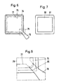
- Figur 6 und 7 jeweils in Draufsicht Deckelteil und Unterteil einer abgewandelten Ausführungsform der Verpackung gemäß der Erfindung;
- Figur 8 einen Querschnitt durch den Deckelteil;
- Figur 9 die mit 79 in Figur 6 bezeichnete Einzelheit im größeren Maßstabe in Draufsicht und
- Fig. 10 im größeren Maßstabe einen Querschnitt durch den K reuzungsbereich zwischen einer Grifflasche und einer Siegellinie einer Verpackung gemäß der Erfindung.
- Die Verpackung gemäß den Figuren 1 bis 5 umfaßt einen Deckelteil 60 aus einem Folienmaterial, das z.B. eine außenliegende Metall-, z.B. Aluminiumfolie 66 und eine z.B. Siegelfähige Kunststoffschicht 67 auf deren Unterseite um faßt. Im Abstand vom Rand des Deckelteils ist durch eine umlaufende Schwächungslinie 64 ein Aufreißbereich begrenzt. Im Bereich einer Ecke des etwa quadratischen Deckelteils ist der Aufreißteil mit einer über den Rand des Deckelteils vorspringenden Grifflasche 65 einstückig verbunden. Der Deckelteil 60 kann eben ausgebildet sein, wie dies dargestellt ist, oder in gewünschter Weise profiliert sein. Die Deckelfolie kann auch noch eine äußere L ackschicht oder dgl. tragen die zur Beschriftung oder anderweitigen Ausgestaltung der Deckelaußenfläche dient.
- Der Deckelteil 60 wird fest und abdichtend mit dem Randflansch 62 eines Unterteils 61, z.B. durch Kleben,Schweißen oder Kalt- oder Heißsiegeln in einem Flächenbereich verbunden, der entlang einer umlaufenden Siegellinie 63 orientiert ist.
- Wie insb. Figur 5 zeigt, ist der Unterteil aus einer Verbundfolie hergestellt. Diese besteht z.B. aus drei Schichten, nämlich einer außenliegenden Metallfolie 73, einer mittleren Kunststoffschicht 72 und einer innenliegenden Kunststoffschicht aus schweiß- oder siegelfähigem Material. Die mittlere Schicht 72 ist so gewählt, daß sich unter bestimmten Kräften die Siegelschicht 71 und die mittlere Schicht 72 voneinander durch Abschälen delaminieren lassen. Derartige Verbundfolien sind z.B. aus der eingangs genannten DE- OS 36 13 155 bekannt. Bei Bedarf kann die äußere Aluminiumschicht 73 noch eine äußere Schutzlackschicht tragen.
- Wie aus den Figuren 4 und 5 hervorgeht, ist in dem Eckbereich des R andflansches 62 des Unterteils, an dem die Grifflasche 65 des Deckelteils über die Verpackung hinausragt, eine zusätzliche Schwächunglinie oder Ritzung 70 vorgesehen, die in der Einzelheit 69 gemäß Figur 4 näher dargestellt ist. Man erkennt, daß die Ritzung 70 im Eckbereich die Siegellinie 63 einschließt und nur beim Kreuzen der Siegellinie unterbrochen ist. Die Ausdehnung des durch die Ritzung 70 begrenzten Bereiches entlang der Siegellinie 63 ist durch die Breite der Grifflasche 65 im Kreuzungsbereich mit dem Randflansch 62 bestimmt. Die Anordnung ist so getroffen, daß die Haftkraft entlang der Siegellinie 63 größer ist als die H aftkraft zwischen den Schichten 71 und 62 des Unterteils. Soll also die Verpackung geöffnet werden und wird an der Grifflasche 65 eine entsprechende Öffnungskraft aufgebracht, so verbleibt der durch die Ritzung 70 eng begrenzte Bereich der Schicht 71 über die Siegellinie 63 fest mit dem Deckelteil 60 verbunden und schält sich vom Rand des Unterteils 61 ab, so daß die Grifflasche vom Unterteil leicht gelöst werden kann und anschließend durch Einleiten der Aufreißkraft in die Sch wächungslinie 64 das gewollte Aufreißen des Deckelteils einleitet.
- Bei der Ausführungsform nach den Figuren 6 bis 9 ist der Deckelteil 75 aus einer Verbundfolie hergestellt. Diese kann z.B. aus einer Aluminiumfolie 84 mit äußerer Schutzlackschicht 82, einer Delaminierungsschicht 85 und einer Heißsiegelschicht 83 bestehen. Der Aufreißbereich ist durch eine auf der Außenseite des Deckelteils liegende Schwächungslinie 77 begrenzt. Der Deckelteil 77 wird entlang der Verbindungs- oder Siegellinie 76 mit dem Randflansch 81 des Unterteils 80 abdichtend und fest verbunden. Der Deckelteil weist eine Grifflasche 78 auf, die über den Randflansch 81 des Unterteils hinausragt. Im Kreuzungsbereich der Grifflasche 78 mit dem Randflansch ist auf der Unterseite des Deckelteils ehe im wesentlichen in sich geschlossene Ritzung 86 vorgesehen, welche die Siegelschicht 83 und teilweise auch die Delaminierungsschicht 85 betrifft. Beim Öffnen der Packung löst sich unter der durch die Grifflasche 78 eingeleiteten Kraft die Siegelschicht 83 oder die Delaminierungsschicht 85 von der Schicht 91 oder bricht in sich auf. Die Verbindung entlang der Siegellinie 76 bleibt zwischen dem Rand 81 des Unterteils und dem Deckelteil intakt, während die Grifflasche 78 sich von diesem Rand löst und das Öffnen durch Einreißen der Schwächungslinie 77 ermöglicht.
Die Einzelheiten im Kreuzungsbereich sind im Querschnitt und im größeren Maßstabe in Figur 10 noch einmal dargestellt. Man erkennt, daß die Delaminierung nicht unbedingt zwischen der Schicht 83 und der Schicht 85 erfolgen muß. Es kann vielmehr auch ein Abbruch innerhalb der Schicht 85 erfolgen, wie dies in der Figur 10 angedeutet und oben schon erwähnt ist. - Der Unterteil kann ebenfalls aus einer Verbundfolie, z.B.einerAluminiumfolie 90 mit Siegelschicht 91 bestehen. Die Breite der Siegellinie ist im Berührungsbereich der beiden Teile stärker ausgezogen dargestellt. Beiderseits der Siegellinie verläuft die Ritzung 86.
- Es ist ersichtlich, daß ein solcher eng begrenzter Ablösebereich zwischen Deckelteil und Unterteil nicht nur im Randflansch des Unterteils vorgesehen sein kann. Falls der Unterteil durch Stege oder Rippen in zwei oder mehr Kammern unterteilt ist, wird der Deckelteil auch mit der Oberseite der Trennstege entlang einer Siegellinie verschweißt. Auch hier kann im Bereich der Stege ein eng begrenzter Kreuzungsbereich in der anhand den Figuren beschriebenen Weise mit einem Ablöseverhalten durch Abschälen ausgestattet sein. Dies kann z.B. sinnvoll sein um den Öffnungsvorgang von einem Kammerbereich zu dem anderen Kammerbereich nur über begrenzte Flächenbereiche der Stege übergehen zu lassen.
Claims (5)
Applications Claiming Priority (2)
| Application Number | Priority Date | Filing Date | Title |
|---|---|---|---|
| DE3901503 | 1989-01-19 | ||
| DE3901503A DE3901503A1 (de) | 1989-01-19 | 1989-01-19 | Leicht zu oeffnende verpackung |
Publications (2)
| Publication Number | Publication Date |
|---|---|
| EP0379934A1 true EP0379934A1 (de) | 1990-08-01 |
| EP0379934B1 EP0379934B1 (de) | 1993-10-27 |
Family
ID=6372401
Family Applications (1)
| Application Number | Title | Priority Date | Filing Date |
|---|---|---|---|
| EP90100810A Expired - Lifetime EP0379934B1 (de) | 1989-01-19 | 1990-01-16 | Leicht zu öffnende Verpackung |
Country Status (7)
| Country | Link |
|---|---|
| US (1) | US5002223A (de) |
| EP (1) | EP0379934B1 (de) |
| JP (1) | JPH02233358A (de) |
| AT (1) | ATE96393T1 (de) |
| DE (2) | DE3901503A1 (de) |
| DK (1) | DK0379934T3 (de) |
| ES (1) | ES2050281T3 (de) |
Cited By (1)
| Publication number | Priority date | Publication date | Assignee | Title |
|---|---|---|---|---|
| WO2015193402A1 (en) * | 2014-06-17 | 2015-12-23 | Torus Pak Research And Development S.À R.L | Food tray and method for producing such a food tray |
Families Citing this family (24)
| Publication number | Priority date | Publication date | Assignee | Title |
|---|---|---|---|---|
| US5176314A (en) * | 1989-12-25 | 1993-01-05 | Sumitomo Bakelite Company Limited | Easily openable sealed container |
| JP2724355B2 (ja) * | 1990-06-15 | 1998-03-09 | 出光石油化学株式会社 | 易開封性容器及びその製造方法 |
| DK123591A (da) * | 1991-06-25 | 1992-12-26 | Schur Int As Brdr | Genlukkelig salgsforpakning, f.eks. til skivepaalaeg |
| AU7601794A (en) * | 1993-09-03 | 1995-03-22 | Procter & Gamble Company, The | Improved tear-away canister lid |
| DE4410206A1 (de) * | 1994-03-24 | 1995-09-28 | Tetra Laval Holdings & Finance | Fließmittelpackung mit teilweise abreißbarer Greiflasche |
| WO1997029976A1 (de) * | 1996-02-15 | 1997-08-21 | Dynamit Nobel Gmbh Explosivstoff- Und Systemtechnik | Abdeckung für einen behälter |
| US5979748A (en) * | 1997-02-06 | 1999-11-09 | Sonoco Development, Inc. | Tubular container with a heat seal having an inner and outer bead and method of manufacturing said container |
| US6264098B1 (en) | 1997-02-06 | 2001-07-24 | Sonoco Development, Inc. | Tubular container with a heat seal having non-symmetrical inner and outer beads |
| US5868307A (en) * | 1997-08-11 | 1999-02-09 | Westvaco Corporation | Carton opening feature |
| IT1296883B1 (it) * | 1997-12-18 | 1999-08-02 | Safta Spa | Sistema di confezionamento richiudibile e relativi procedimenti di fabbricazione |
| TW540468U (en) * | 1997-12-18 | 2003-07-01 | Safta Spa | A flexible composite foil |
| DE19847125A1 (de) * | 1998-10-13 | 2000-04-20 | Zimmer Detlef | Gestaltung von Verpackungsmaterialien derart, daß Unterscheidungsmerkmale entstehen, die durch die unterschiedlichen Sinne (z. B. Tast- und Sehsinn) wahrgenommen werden können und Orientierungshilfen bieten, an Verpackung angebrachte Öffnungshilfen zu finden und die Lage von Gegenständen innerhalb der Verpackung (d. h. wo sich z. B. Ober- und Unterseite von Gegenständen befinden) bereits von außen (außerhalb der Verpackung) zu erkennen |
| FR2797622B1 (fr) * | 1999-08-17 | 2001-11-02 | Danisco Flexible France | Feuille d'emballage stratifiee permettant la refermeture et emballage la comportant |
| JP4550971B2 (ja) * | 2000-06-23 | 2010-09-22 | 共同印刷株式会社 | 密封容器の蓋体 |
| JP2004513036A (ja) * | 2000-11-13 | 2004-04-30 | ザ プロクター アンド ギャンブル カンパニー | 取外し可能な閉鎖デバイス |
| MY138157A (en) * | 2002-03-07 | 2009-04-30 | Brasilata Embalagens Metalicas | Plastic lid for a can |
| DE10359035A1 (de) * | 2003-12-15 | 2005-07-14 | Huhtamaki Alf Zweigniederlassung Der Huhtamaki Deutschland Gmbh & Co. Kg | Behälter mit Deckel |
| DE102006046664B4 (de) * | 2006-09-29 | 2011-03-31 | Sig Technology Ag | Packung mit peelfähigem Deckel |
| WO2008131424A1 (en) * | 2007-04-23 | 2008-10-30 | Wm. Wrigley Jr. Company | Refillable package for consumable products |
| MX363996B (es) | 2012-07-11 | 2019-04-09 | Gayer Mark | Aparato de cubierta multi-porcion removible y metodos relacionados. |
| US11414253B2 (en) * | 2012-07-11 | 2022-08-16 | Mark Gayer | Multi-portion removable cover apparatus and related methods |
| US20150041357A1 (en) * | 2013-08-08 | 2015-02-12 | Richards Packaging Inc. -Emballages Richards Inc. | Cover sheet for pill receptacle and pillbox kit comprising same |
| JP6659362B2 (ja) * | 2016-01-08 | 2020-03-04 | 凸版印刷株式会社 | 紙製蓋材及び収納容器 |
| CH719573A1 (de) * | 2022-04-05 | 2023-10-13 | Alfabio S R I | Behältersystem zum Aufbewahren und Transportieren von Lebensmitteln. |
Citations (5)
| Publication number | Priority date | Publication date | Assignee | Title |
|---|---|---|---|---|
| DE7024068U (de) * | Kraemer & Grebe Kg | Warenpackung | ||
| DE6901362U (de) * | 1969-01-14 | 1969-05-14 | Stork Amsterdam | Kunststoffbehaelter mit ausgussoeffnung |
| EP0004834A2 (de) * | 1978-04-10 | 1979-10-17 | AB Akerlund & Rausing | Verschlusselemente für Behälter |
| CH634520A5 (en) * | 1979-02-06 | 1983-02-15 | Verbandsmolkerei Region Bern A | Tear-open container |
| DE3613155A1 (de) * | 1986-04-18 | 1987-11-05 | Schmalbach Lubeca | Leicht zu oeffnende verpackung aus kunststoff |
Family Cites Families (8)
| Publication number | Priority date | Publication date | Assignee | Title |
|---|---|---|---|---|
| US3159303A (en) * | 1961-08-04 | 1964-12-01 | Acme Plate & Mat Company | Tear-open sealed containers |
| US3572579A (en) * | 1969-04-11 | 1971-03-30 | American Can Co | Scored peripheral tear strip with reclosure lid |
| US4351473A (en) * | 1980-11-17 | 1982-09-28 | Federal Paper Board Co., Inc. | Tray container with tear out cover |
| JPS59199461A (ja) * | 1983-04-23 | 1984-11-12 | テルモ株式会社 | 包装容器およびその密封方法 |
| US4913307A (en) * | 1986-09-30 | 1990-04-03 | Idemitsu Petrochemical Co., Ltd. | Easily openable packaging container and method for producing the same |
| US4693390A (en) * | 1986-10-15 | 1987-09-15 | Continental Can Company, Inc. | Lid for a plastic container |
| US4865217A (en) * | 1987-08-31 | 1989-09-12 | Sumitomo Bakelite Company, Limited | Easily openable sealed container |
| DE3902912A1 (de) * | 1989-01-19 | 1990-08-02 | Schmalbach Lubeca | Leicht zu oeffnende verpackung |
-
1989
- 1989-01-19 DE DE3901503A patent/DE3901503A1/de active Granted
-
1990
- 1990-01-11 US US07/463,369 patent/US5002223A/en not_active Expired - Fee Related
- 1990-01-16 EP EP90100810A patent/EP0379934B1/de not_active Expired - Lifetime
- 1990-01-16 AT AT90100810T patent/ATE96393T1/de active
- 1990-01-16 ES ES90100810T patent/ES2050281T3/es not_active Expired - Lifetime
- 1990-01-16 DK DK90100810.2T patent/DK0379934T3/da active
- 1990-01-16 DE DE90100810T patent/DE59003174D1/de not_active Expired - Fee Related
- 1990-01-17 JP JP2006483A patent/JPH02233358A/ja active Pending
Patent Citations (5)
| Publication number | Priority date | Publication date | Assignee | Title |
|---|---|---|---|---|
| DE7024068U (de) * | Kraemer & Grebe Kg | Warenpackung | ||
| DE6901362U (de) * | 1969-01-14 | 1969-05-14 | Stork Amsterdam | Kunststoffbehaelter mit ausgussoeffnung |
| EP0004834A2 (de) * | 1978-04-10 | 1979-10-17 | AB Akerlund & Rausing | Verschlusselemente für Behälter |
| CH634520A5 (en) * | 1979-02-06 | 1983-02-15 | Verbandsmolkerei Region Bern A | Tear-open container |
| DE3613155A1 (de) * | 1986-04-18 | 1987-11-05 | Schmalbach Lubeca | Leicht zu oeffnende verpackung aus kunststoff |
Cited By (2)
| Publication number | Priority date | Publication date | Assignee | Title |
|---|---|---|---|---|
| WO2015193402A1 (en) * | 2014-06-17 | 2015-12-23 | Torus Pak Research And Development S.À R.L | Food tray and method for producing such a food tray |
| CN106470918A (zh) * | 2014-06-17 | 2017-03-01 | 图鲁斯帕克研究与发展有限责任公司 | 食品托盘及用于制造该食品托盘的方法 |
Also Published As
| Publication number | Publication date |
|---|---|
| US5002223A (en) | 1991-03-26 |
| ATE96393T1 (de) | 1993-11-15 |
| DE59003174D1 (de) | 1993-12-02 |
| EP0379934B1 (de) | 1993-10-27 |
| DE3901503A1 (de) | 1990-08-02 |
| JPH02233358A (ja) | 1990-09-14 |
| ES2050281T3 (es) | 1994-05-16 |
| DE3901503C2 (de) | 1992-06-11 |
| DK0379934T3 (da) | 1994-02-07 |
Similar Documents
| Publication | Publication Date | Title |
|---|---|---|
| EP0379934B1 (de) | Leicht zu öffnende Verpackung | |
| EP0104548B1 (de) | Behälterdeckel mit Öffnungseinrichtung | |
| EP0129102B1 (de) | Behälterdeckel mit Öffnungseinrichtung | |
| DE68911863T2 (de) | Öffnungsanordnung auf einem Verpackungsbehälter. | |
| DE69033062T2 (de) | Innendichtung mit Z-förmiger Aufreislasche für Behälter | |
| DE3901517C2 (de) | ||
| DE3901482C1 (de) | ||
| WO1983000677A1 (fr) | Emballage avec enveloppe etanche aux gaz | |
| DE3700988A1 (de) | Verpackung aus thermoplastischer kunststoffolie | |
| DE4409947A1 (de) | Quaderförmige Flachgiebelpackung | |
| EP0408831A1 (de) | Leicht zu öffnender Deckel für Verpackungen, insbesondere Getränkedosen | |
| DE3301086C2 (de) | Packung auf flächigem Material, wie z.B. Papier, Karton o.dgl. insbesondere quaderförmige Flüssigkeitspackung aus Papier-Kunststoff- Verbund-Material | |
| CH666458A5 (de) | Verpackungsbehaelter. | |
| EP0386416A1 (de) | Leicht zu öffnende Verpackung | |
| DE3613155C2 (de) | Leicht zu öffnende Verpackung aus Kunststoff | |
| EP0664759B1 (de) | Verfahren zur herstellung einer fliessmittelverpackung und werkzeug zur durchführung des verfahrens | |
| DE60211851T2 (de) | Verpackung für einen rohrförmigen stapel von runden keksen | |
| DE69001920T2 (de) | Verpackungsbehaelter mit oeffnungsvorrichtung. | |
| EP0553413B1 (de) | Wiederverschliessbarer Verpackungsbeutel | |
| DE4410206A1 (de) | Fließmittelpackung mit teilweise abreißbarer Greiflasche | |
| DE60019380T2 (de) | Wiederverschliessbares mehrschichtige Verpackungsfolie und damit hergestellte Verpackung | |
| DE19947296A1 (de) | Mit einem wiederschliessbaren Ausgiesser versehene Flachgiebelverbundpackung und Verfahren zu ihrer Herstellung | |
| DE3901489C2 (de) | ||
| EP0663884B1 (de) | Durch siegeln verschliessbarer, nach dem ersten öffnen wiederverschliessbarer behälter, sowie verfahren und folie zu seiner herstellung | |
| DE69002499T2 (de) | Verpackung, insbesondere für unter Druck stehende Flüssigkeiten. |
Legal Events
| Date | Code | Title | Description |
|---|---|---|---|
| PUAI | Public reference made under article 153(3) epc to a published international application that has entered the european phase |
Free format text: ORIGINAL CODE: 0009012 |
|
| AK | Designated contracting states |
Kind code of ref document: A1 Designated state(s): AT BE CH DE DK ES FR GB GR IT LI LU NL SE |
|
| 17P | Request for examination filed |
Effective date: 19900911 |
|
| 17Q | First examination report despatched |
Effective date: 19921005 |
|
| GRAA | (expected) grant |
Free format text: ORIGINAL CODE: 0009210 |
|
| AK | Designated contracting states |
Kind code of ref document: B1 Designated state(s): AT BE CH DE DK ES FR GB GR IT LI LU NL SE |
|
| REF | Corresponds to: |
Ref document number: 96393 Country of ref document: AT Date of ref document: 19931115 Kind code of ref document: T |
|
| REF | Corresponds to: |
Ref document number: 59003174 Country of ref document: DE Date of ref document: 19931202 |
|
| ITF | It: translation for a ep patent filed | ||
| PGFP | Annual fee paid to national office [announced via postgrant information from national office to epo] |
Ref country code: SE Payment date: 19940131 Year of fee payment: 5 Ref country code: NL Payment date: 19940131 Year of fee payment: 5 |
|
| REG | Reference to a national code |
Ref country code: DK Ref legal event code: T3 |
|
| GBT | Gb: translation of ep patent filed (gb section 77(6)(a)/1977) |
Effective date: 19940216 |
|
| ET | Fr: translation filed | ||
| REG | Reference to a national code |
Ref country code: GR Ref legal event code: FG4A Free format text: 3010578 |
|
| REG | Reference to a national code |
Ref country code: ES Ref legal event code: FG2A Ref document number: 2050281 Country of ref document: ES Kind code of ref document: T3 |
|
| PGFP | Annual fee paid to national office [announced via postgrant information from national office to epo] |
Ref country code: ES Payment date: 19940714 Year of fee payment: 5 |
|
| PGFP | Annual fee paid to national office [announced via postgrant information from national office to epo] |
Ref country code: FR Payment date: 19940725 Year of fee payment: 5 |
|
| PGFP | Annual fee paid to national office [announced via postgrant information from national office to epo] |
Ref country code: GR Payment date: 19940729 Year of fee payment: 5 Ref country code: DK Payment date: 19940729 Year of fee payment: 5 Ref country code: CH Payment date: 19940729 Year of fee payment: 5 Ref country code: BE Payment date: 19940729 Year of fee payment: 5 |
|
| PGFP | Annual fee paid to national office [announced via postgrant information from national office to epo] |
Ref country code: LU Payment date: 19940731 Year of fee payment: 5 |
|
| PLBE | No opposition filed within time limit |
Free format text: ORIGINAL CODE: 0009261 |
|
| STAA | Information on the status of an ep patent application or granted ep patent |
Free format text: STATUS: NO OPPOSITION FILED WITHIN TIME LIMIT |
|
| PGFP | Annual fee paid to national office [announced via postgrant information from national office to epo] |
Ref country code: DE Payment date: 19940927 Year of fee payment: 5 |
|
| EPTA | Lu: last paid annual fee | ||
| 26N | No opposition filed | ||
| PGFP | Annual fee paid to national office [announced via postgrant information from national office to epo] |
Ref country code: GB Payment date: 19950113 Year of fee payment: 6 |
|
| PG25 | Lapsed in a contracting state [announced via postgrant information from national office to epo] |
Ref country code: LU Free format text: LAPSE BECAUSE OF NON-PAYMENT OF DUE FEES Effective date: 19950116 Ref country code: DK Effective date: 19950116 Ref country code: AT Effective date: 19950116 |
|
| REG | Reference to a national code |
Ref country code: DK Ref legal event code: EBP |
|
| PG25 | Lapsed in a contracting state [announced via postgrant information from national office to epo] |
Ref country code: SE Effective date: 19950117 Ref country code: ES Free format text: LAPSE BECAUSE OF NON-PAYMENT OF DUE FEES Effective date: 19950117 |
|
| EAL | Se: european patent in force in sweden |
Ref document number: 90100810.2 |
|
| PG25 | Lapsed in a contracting state [announced via postgrant information from national office to epo] |
Ref country code: LI Effective date: 19950131 Ref country code: CH Effective date: 19950131 Ref country code: BE Effective date: 19950131 |
|
| PGFP | Annual fee paid to national office [announced via postgrant information from national office to epo] |
Ref country code: AT Payment date: 19950131 Year of fee payment: 5 |
|
| BERE | Be: lapsed |
Owner name: SCHMALBACH-LUBECA A.G. Effective date: 19950131 |
|
| PG25 | Lapsed in a contracting state [announced via postgrant information from national office to epo] |
Ref country code: GR Free format text: THE PATENT HAS BEEN ANNULLED BY A DECISION OF A NATIONAL AUTHORITY Effective date: 19950731 |
|
| PG25 | Lapsed in a contracting state [announced via postgrant information from national office to epo] |
Ref country code: NL Effective date: 19950801 |
|
| PG25 | Lapsed in a contracting state [announced via postgrant information from national office to epo] |
Ref country code: FR Effective date: 19950929 |
|
| REG | Reference to a national code |
Ref country code: CH Ref legal event code: PL |
|
| REG | Reference to a national code |
Ref country code: GR Ref legal event code: MM2A Free format text: 3010578 |
|
| NLV4 | Nl: lapsed or anulled due to non-payment of the annual fee |
Effective date: 19950801 |
|
| PG25 | Lapsed in a contracting state [announced via postgrant information from national office to epo] |
Ref country code: DE Effective date: 19951003 |
|
| EUG | Se: european patent has lapsed |
Ref document number: 90100810.2 |
|
| REG | Reference to a national code |
Ref country code: FR Ref legal event code: ST |
|
| PG25 | Lapsed in a contracting state [announced via postgrant information from national office to epo] |
Ref country code: GB Effective date: 19960116 |
|
| GBPC | Gb: european patent ceased through non-payment of renewal fee |
Effective date: 19960116 |
|
| REG | Reference to a national code |
Ref country code: ES Ref legal event code: FD2A Effective date: 19990503 |
|
| PG25 | Lapsed in a contracting state [announced via postgrant information from national office to epo] |
Ref country code: IT Free format text: LAPSE BECAUSE OF NON-PAYMENT OF DUE FEES;WARNING: LAPSES OF ITALIAN PATENTS WITH EFFECTIVE DATE BEFORE 2007 MAY HAVE OCCURRED AT ANY TIME BEFORE 2007. THE CORRECT EFFECTIVE DATE MAY BE DIFFERENT FROM THE ONE RECORDED. Effective date: 20050116 |