EP0379952A2 - Gasdüse für Gasbohrungen - Google Patents
Gasdüse für Gasbohrungen Download PDFInfo
- Publication number
- EP0379952A2 EP0379952A2 EP90100885A EP90100885A EP0379952A2 EP 0379952 A2 EP0379952 A2 EP 0379952A2 EP 90100885 A EP90100885 A EP 90100885A EP 90100885 A EP90100885 A EP 90100885A EP 0379952 A2 EP0379952 A2 EP 0379952A2
- Authority
- EP
- European Patent Office
- Prior art keywords
- gas
- gas nozzle
- nozzle
- bore
- bores
- Prior art date
- Legal status (The legal status is an assumption and is not a legal conclusion. Google has not performed a legal analysis and makes no representation as to the accuracy of the status listed.)
- Granted
Links
Images

Classifications
-
- F—MECHANICAL ENGINEERING; LIGHTING; HEATING; WEAPONS; BLASTING
- F41—WEAPONS
- F41A—FUNCTIONAL FEATURES OR DETAILS COMMON TO BOTH SMALLARMS AND ORDNANCE, e.g. CANNONS; MOUNTINGS FOR SMALLARMS OR ORDNANCE
- F41A5/00—Mechanisms or systems operated by propellant charge energy for automatically opening the lock
- F41A5/18—Mechanisms or systems operated by propellant charge energy for automatically opening the lock gas-operated
- F41A5/26—Arrangements or systems for bleeding the gas from the barrel
Definitions
- the invention relates to a gas nozzle for gas bores in workpieces, in particular for use in gas extraction bores of weapon tubes, with a device for assembly and disassembly in / from such gas bores.
- the gas nozzle has a projecting pin with an external thread, onto which a dismantling tool in the form of a hollow nut with an internal thread can be screwed, and in that an assembly tool is provided with an internal bore and an external thread, which is provided with an internal thread of the nozzle bore is engaged and acts axially against the shoulder of the gas nozzle around the pin.
- the hollow nut can have a tool engagement device for the rotary entrainment in its outwardly facing end face.
- the lower fitting shape of the gas nozzle can be formed in one piece with the gas nozzle and have a design that deviates from the symmetrical shape.
- an optionally straight, curved or angled nozzle bore can be provided.
- a gas nozzle with the features of the invention facilitates both its assembly and its disassembly in a gas bore of a weapon barrel.
- a tight fit is achieved in all operating conditions in a nozzle bore. Since the gas nozzle is fitted into the recess by means of a threaded screw connection with the assembly tool, tilting of the gas nozzle or pressing up is avoided in principle. Due to the fits on the lower face of the gas nozzle, this gas nozzle only ever fits into a recess provided for it, while at the same time ensuring a correct fit with respect to the nozzle bore and the gas bore.
- the gas nozzle 1 consists of a cylindrical base body with a lower end face 2, which has a fit 5 or 5.1 corresponding to Figures 3 and 4. These fits 5 and 5.1 of the gas nozzle 1 are inserted into corresponding recesses in the workpiece 9 and allow the insertion of a gas nozzle 1 only in the recess provided for them. In addition, this always ensures that axes are identical between the nozzle bores 13 and the gas bore 10.
- the upper end face 4 of the gas nozzle 1 has a pin 3 with an external thread 6.
- This external thread 6 serves to receive a screw-on dismantling tool 14 in the form of a hollow nut with an internal thread 15.
- the gas nozzle 1 is consequently dismantled by unscrewing the tool 14 and pulling the gas nozzle 1 out of the nozzle bore 13 after the assembly tool 12 has been removed.
- the assembly tool 12 has an external thread 8 and can be screwed into the internal thread 7 of the nozzle bore 13.
- the assembly tool 12 is in contact with its axial end face on the shoulder 16 of the gas nozzle 1 around the pin 3.
- the gas nozzle 1 can be pressed firmly into the lower fit 5 or 5.1 with the assembly tool 12, so that a perfect passage opening in the gas nozzle 1 with the gas bore 10 takes place.
- the screw connection between the assembly tool 12 and the workpiece 9 ensures a good and permanent fit of the gas nozzle 1 even under operating loads.
- the nozzle 1 shown in FIG. 1 shows a rectilinear inner nozzle passage bore 17 which is connected at its opposite ends to a gas extraction bore 10 of the workpiece 9.
- the workpiece 9 is a weapon barrel in the example shown.
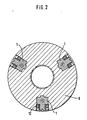
- FIG. 2 shows, in the example shown, a total of three gas nozzles 1 are arranged at an angle of 120 ° to one another on a cross-sectional area.
- a total of three gas nozzles 1 are arranged at an angle of 120 ° to one another on a cross-sectional area.
- other arrangements and other quantities of gas nozzles in a cross-sectional plane are also possible.
- the fits 5 and 5.1 according to FIGS. 3 and 4 can be formed differently.
- the fits 5 and 5.1 formed in one piece with the gas nozzle 1 are designed in a design that deviates from the symmetrical shape.
Landscapes
- Engineering & Computer Science (AREA)
- General Engineering & Computer Science (AREA)
- Nozzles (AREA)
- Perforating, Stamping-Out Or Severing By Means Other Than Cutting (AREA)
Abstract
Die Gasdüse weist ferner eine Passform (5, 5.1) als Drehsicherung und Sicherung gegen Vertauschen der Gasdüse (1) auf.
Description
- Die Erfindung betrifft eine Gasdüse für Gasbohrungen in Werkstücken, insbesondere für den Einsatz in Gasentnahmebohrungen von Waffenrohren, mit einer Einrichtung zur Montage und Demontage in/aus solchen Gasbohrungen.
- In der Praxis ist es allgemein bekannt, daß die in Gasentnahmebohrungen von Waffenrohren eingesetzten Gasdüsen in entsprechende Ausnehmungen des Werkstückes mit einem Pressitz oder Schiebesitz eingesetzt werden. Dabei hat sich als nachteilig herausgestellt, daß sich vor allem bei der Anwendung in Waffenrohren auf der Unterseite der Düse Schmutz und auch Pulverschleim absetzen konnte. Diese Verunreinigungen verursachten ein langsames Hochdrücken der Gasdüse und teilweise ein Verkanten derselben, wodurch der Gasdurchgang verschlechtert bis unmöglich gemacht wurde. Außerdem bereitete es eine besondere Mühe und regelmäßig Spezialwerkzeuge, um solche eingepressten Gasdüsen nach längerem Gebrauch aus der Ausnehmung des Werkstückes herauszubringen.
- Ausgehend von dem vorgenannten Stand der Technik ist es Aufgabe der Erfindung, eine Gasdüse der eingangs genannten Art zu schaffen, bei welcher auch im längeren Betrieb ein Verkanten oder Hochdrücken der Gasdüse verhindert und die Möglichkeit des einfachen Einsatzes und der einfachen Herausnahme der Gasdüse aus der Ausnehmung des Werkstückes gewährleistet ist.
- Erfindungsgemäß wird diese Aufgabe dadurch gelöst, daß die Gasdüse einen vorstehenden Zapfen mit einem Außengewinde aufweist, auf das ein Demontagewerkzeug in Form einer Hohlmutter mit Innengewinde aufschraubbar ist, und daß ein Montagewerkzeug mit einer Innenbohrung und einem Außengewinde vorgesehen ist, welches mit einem Innengewinde der Düsenbohrung im Eingriff steht und axial gegen die Schulter der Gasdüse um den Zapfen wirkt.
- Dabei kann die Hohlmutter in ihrer nach außen gewandten Stirnfläche eine Werkzeugeingriffseinrichtung für die Drehmitnahme aufweisen. Die untere Pass-Form der Gasdüse kann einstückig mit der Gasdüse gebildet sein und eine von der symmetrischen Form abweichende Gestaltung besitzen. Schließlich kann eine wahlweise geradlinie, gebogene oder abgewinkelte Düsenbohrung vorgesehen sein.
- Eine Gasdüse mit den erfindungsgemäßen Merkmalen erleichtert sowohl ihre Montage als auch ihre Demontage in eine Gasbohrung eines Waffenrohres. Dabei wird ein fester Sitz bei allen auftretenden Betriebsbedingungen in einer Düsenbohrung erzielt. Da die Gasdüse durch eine Gewindeverschraubung mit dem Montagewerkzeug in die Ausnehmung eingepaßt ist, wird ein Verkanten der Gasdüse oder ein Hochdrücken grundsätzlich vermieden. Aufgrund der Passformen an der unteren Stirnseite der Gasdüse paßt diese Gasdüse immer nur in eine nur für sie vorgesehene Ausnehmung, wobei zugleich ein richtiger Sitz in Bezug auf die Düsenbohrung und die Gasbohrung gewährleistet wird.
- In der Zeichnung ist ein Beispiel der Erfindung dargestellt. Es zeigen:
- Fig. 1 eine Gasdüse in einer Gasbohrung eines Werkstückes im Schnitt
- Fig. 2 einen Schnitt durch die Gasdüse entsprechend der Linie II-II in Fig. 1
- Fig. 3 eine Draufsicht auf die Unterseite der Gasdüse gemäß dem Pfeil III in Fig. 1
- Fig. 4 eine Draufsicht auf die untere Stirnseite der Gasdüse mit zur Fig. 3 unterschiedlichen Passform.
- Die Gasdüse 1 besteht aus einem zylindrischen Grundkörper mit einer unteren Stirnfläche 2, die eine Passform 5 bzw. 5.1 entsprechend den Figuren 3 und 4 besitzt. Diese Passformen 5 bzw. 5.1 der Gasdüse 1 sind in entsprechende Ausnehmungen des Werkstückes 9 eingesetzt, und erlauben das Einsetzen einer Gasdüse 1 immer nur in die für sie vorgesehene Ausnehmung. Außerdem wird dadurch stets Achsgleichheit zwischen den Düsenbohrungen 13 und der Gasbohrung 10 errzielt.
- Die obere Stirnseite 4 der Gasdüse 1 weist einen Zapfen 3 mit einem Außengewinde 6 auf. Dieses Außengewinde 6 dient zur Aufnahme eines aufschraubbaren Demontagewerkzeuges 14 in Form einer Hohlmutter mit einem Innengewinde 15. Die Demontage der Gasdüse 1 erfolgt demzufolge durch Aufschrauben des Werkzeuges 14 und Herausziehen der Gasdüse 1 aus der Düsenbohrung 13, nachdem das Montagewerkzeug 12 entfernt wurde. Das Montagewerkzeug 12 besitzt ein Außengewinde 8 und ist in das Innengewinde 7 der Düsenbohrung 13 einschraubbar. Dabei steht das Montagewerkzeug 12 mit seiner axialen Stirnseite auf der Schulter 16 der Gasdüse 1 um den Zapfen 3 an. Dies bedeutet, daß die Gasdüse 1 mit dem Montagewerkzeug 12 fest in die untere Paßform 5 oder 5.1 anpreßbar ist, sodaß eine einwandfreie Durchlaßöffnung in der Gasdüse 1 mit der Gasbohrung 10 erfolgt. Die Schraubverbindung zwischen dem Montagewerkzeug 12 und dem Werkstück 9 gewährleistet eine guten und bleibenden Sitz der Gasdüse 1 auch bei Betriebsbelastungen.
- Die in Fig. 1 dargestellte Düse 1 zeigt eine geradlinige innere Düsendurchlaßbohrung 17, die an ihren gegenüberliegenden Enden mit einer Gasentnahmebohrung 10 des Werkstücks 9 in Verbindung steht. Das Werkstück 9 ist in dem dargestellten Beispiel ein Waffenrohr.
- Wir Fig. 2 zeigt, sind in dem dargestellten Beispiel auf einer Querschnittsfläche insgesamt drei Gasdüsen 1 in einem Winkel von jeweils 120° zueinander angeordnet. Selbstverständlich sind auch andere Anordnungen und andere Mengen von Gasdüsen in einer Querschnittsebene möglich.
- Die Passformen 5 bzw. 5.1 nach den Figuren 3 und 4 können unterschiedlich gebildet sind. Um eine einwandfreie Zuordnung der Gasdüse über diese Passformen 5 bzw. 5.1 zu erzielen, sind die einstückig mit der Gasdüse 1 gebildeten Passformen 5. bzw. 5.1 in einer von der symmetrischen Form abweichenden Gestaltung ausgeführt.
Claims (5)
dadurch gekennzeichnet,
daß die Gasdüse (1) mit einem zentral vorstehenden Zapfen (3) mit einem Außengewinde (6) versehen ist, auf der ein Demontagewerkzeug in Form einer Hohlmutter (14) mit ihrem Innengewinde (15) aufschraubbar ist, und daß ein Montagewerkzeug (12) mit einer Innenbohrung und einem Außengewinde (8) vorgesehen ist, welches mit einem Innengewinde (7) der Düsenbohrung (13) im Eingriff steht und axial gegen die Schulter (16) der Gasdüse (1) wirkt.
dadurch gekennzeichnet,
daß die untere, dem Zapfen (3) der Gasdüse (1) entgegengesetzte Stirnfläche (2) eine Passform (5, 5.1) besitzt.
dadurch gekennzeichnet,
daß die Hohlmutter (14) an ihrer äußeren Stirnfläche (4) eine Werkzeugeingriffseinrichtung (11) für die Drehmitnahme aufweist.
dadurch gekennzeichnet,
daß die Passform (5, 5.1) einstückig mit der Gasdüse (1) gebildet ist und eine von der symmetrischen Form abweichende Gestaltung besitzt dergestalt, daß beim Einbau der Gasdüse (1) Achsgleichheit zwischen Düsenbohrung (13) und Gasbohrung (10) besteht.
dadurch gekennzeichnet,
daß eine wahlweise geradlinige, gebogene oder abgewinkelte Düsenbohrung (13) vorgesehen ist.
Priority Applications (1)
| Application Number | Priority Date | Filing Date | Title |
|---|---|---|---|
| AT90100885T ATE98012T1 (de) | 1989-01-25 | 1990-01-17 | Gasduese fuer gasbohrungen. |
Applications Claiming Priority (2)
| Application Number | Priority Date | Filing Date | Title |
|---|---|---|---|
| DE3902014A DE3902014A1 (de) | 1989-01-25 | 1989-01-25 | Gasduese fuer gasbohrungen |
| DE3902014 | 1989-01-25 |
Publications (3)
| Publication Number | Publication Date |
|---|---|
| EP0379952A2 true EP0379952A2 (de) | 1990-08-01 |
| EP0379952A3 EP0379952A3 (de) | 1991-09-25 |
| EP0379952B1 EP0379952B1 (de) | 1993-12-01 |
Family
ID=6372680
Family Applications (1)
| Application Number | Title | Priority Date | Filing Date |
|---|---|---|---|
| EP90100885A Expired - Lifetime EP0379952B1 (de) | 1989-01-25 | 1990-01-17 | Gasdüse für Gasbohrungen |
Country Status (4)
| Country | Link |
|---|---|
| EP (1) | EP0379952B1 (de) |
| AT (1) | ATE98012T1 (de) |
| DE (2) | DE3902014A1 (de) |
| ES (1) | ES2047715T3 (de) |
Family Cites Families (3)
| Publication number | Priority date | Publication date | Assignee | Title |
|---|---|---|---|---|
| US1808052A (en) * | 1931-01-31 | 1931-06-02 | George M Mccann | Gun |
| US2775920A (en) * | 1950-05-01 | 1957-01-01 | Paul H Dixon | Bolt spline |
| DE2249545A1 (de) * | 1972-10-10 | 1974-04-18 | Eta Corp | Maschinenrohrfeuerwaffe des gasdruckladesystems |
-
1989
- 1989-01-25 DE DE3902014A patent/DE3902014A1/de not_active Withdrawn
-
1990
- 1990-01-17 EP EP90100885A patent/EP0379952B1/de not_active Expired - Lifetime
- 1990-01-17 ES ES90100885T patent/ES2047715T3/es not_active Expired - Lifetime
- 1990-01-17 DE DE90100885T patent/DE59003638D1/de not_active Expired - Fee Related
- 1990-01-17 AT AT90100885T patent/ATE98012T1/de not_active IP Right Cessation
Also Published As
| Publication number | Publication date |
|---|---|
| DE3902014A1 (de) | 1990-07-26 |
| EP0379952A3 (de) | 1991-09-25 |
| DE59003638D1 (de) | 1994-01-13 |
| ES2047715T3 (es) | 1994-03-01 |
| ATE98012T1 (de) | 1993-12-15 |
| EP0379952B1 (de) | 1993-12-01 |
Similar Documents
| Publication | Publication Date | Title |
|---|---|---|
| DE69919724T2 (de) | Kupplungsvorrichtung | |
| DE20020996U1 (de) | Verbindereinrichtung für Profile | |
| EP0810377A1 (de) | Schraubverbindung zum Verbinden von zwei Profilen | |
| EP0919733A2 (de) | Dübel zur Befestigung von Möbelbeschlagteilen | |
| EP0379952A2 (de) | Gasdüse für Gasbohrungen | |
| EP3828426B1 (de) | Verbindungselement für mehrkantrohre | |
| DE29509140U1 (de) | Verbinder, insbesondere für Handläufe | |
| DE102013101491A1 (de) | Höheneinstellbare Rundstangenführung | |
| DE29505752U1 (de) | Vorrichtung zum Verbinden von Platten mittels Verschraubung | |
| DE3126755A1 (de) | Rohrverschraubung, insbesondere fuer die pharmazeutische industrie | |
| AT525006A1 (de) | Montageprofil | |
| DE102009027473A1 (de) | Klemmverbindung | |
| DE3149408A1 (de) | "einpressmutter mit beweglichem mutterteil" | |
| DE20212169U1 (de) | Brauseschlauch | |
| DE9411537U1 (de) | Entriegelungswerkzeug | |
| DE20212385U1 (de) | Kugelgelenk | |
| DE19960431C1 (de) | Vorrichtung zur Anbringung eines rohrförmigen Leitungselements an einem Behälter | |
| EP2051153A1 (de) | Handhebel | |
| DE202005002687U1 (de) | Verbindereinrichtung für Profile | |
| DE29821143U1 (de) | Abzieher mit schnellverstellbarer Druckspindel | |
| DE4312209B4 (de) | Kupplungskugelträger für Fahrzeug-Anhängerkupplungen | |
| DE2124255C3 (de) | Eckverbindung zweier Möbelteile | |
| DE102017130337A1 (de) | Montagevorrichtung zum Einbringen eines Messelements in eine Ausnehmung eines Bauteils | |
| DE9413609U1 (de) | Vorrichtung zur Befestigung eines Endstückes an einem Ende eines zylindrischen Rohres | |
| DE3206676C2 (de) | Verbindungsvorrichtung mit einer Profilschiene |
Legal Events
| Date | Code | Title | Description |
|---|---|---|---|
| PUAI | Public reference made under article 153(3) epc to a published international application that has entered the european phase |
Free format text: ORIGINAL CODE: 0009012 |
|
| AK | Designated contracting states |
Kind code of ref document: A2 Designated state(s): AT DE ES GB GR IT |
|
| PUAL | Search report despatched |
Free format text: ORIGINAL CODE: 0009013 |
|
| AK | Designated contracting states |
Kind code of ref document: A3 Designated state(s): AT DE ES GB GR IT |
|
| 17P | Request for examination filed |
Effective date: 19910821 |
|
| 17Q | First examination report despatched |
Effective date: 19920710 |
|
| GRAA | (expected) grant |
Free format text: ORIGINAL CODE: 0009210 |
|
| AK | Designated contracting states |
Kind code of ref document: B1 Designated state(s): AT DE ES GB GR IT |
|
| REF | Corresponds to: |
Ref document number: 98012 Country of ref document: AT Date of ref document: 19931215 Kind code of ref document: T |
|
| REF | Corresponds to: |
Ref document number: 59003638 Country of ref document: DE Date of ref document: 19940113 |
|
| ITF | It: translation for a ep patent filed | ||
| REG | Reference to a national code |
Ref country code: ES Ref legal event code: FG2A Ref document number: 2047715 Country of ref document: ES Kind code of ref document: T3 |
|
| GBT | Gb: translation of ep patent filed (gb section 77(6)(a)/1977) |
Effective date: 19940221 |
|
| REG | Reference to a national code |
Ref country code: GR Ref legal event code: FG4A Free format text: 3010557 |
|
| PLBE | No opposition filed within time limit |
Free format text: ORIGINAL CODE: 0009261 |
|
| STAA | Information on the status of an ep patent application or granted ep patent |
Free format text: STATUS: NO OPPOSITION FILED WITHIN TIME LIMIT |
|
| 26N | No opposition filed | ||
| PGFP | Annual fee paid to national office [announced via postgrant information from national office to epo] |
Ref country code: GR Payment date: 19941222 Year of fee payment: 6 |
|
| PGFP | Annual fee paid to national office [announced via postgrant information from national office to epo] |
Ref country code: GB Payment date: 19950109 Year of fee payment: 6 |
|
| PGFP | Annual fee paid to national office [announced via postgrant information from national office to epo] |
Ref country code: ES Payment date: 19950111 Year of fee payment: 6 |
|
| PGFP | Annual fee paid to national office [announced via postgrant information from national office to epo] |
Ref country code: AT Payment date: 19950126 Year of fee payment: 6 |
|
| PGFP | Annual fee paid to national office [announced via postgrant information from national office to epo] |
Ref country code: DE Payment date: 19950317 Year of fee payment: 6 |
|
| PG25 | Lapsed in a contracting state [announced via postgrant information from national office to epo] |
Ref country code: GB Effective date: 19960117 Ref country code: AT Effective date: 19960117 |
|
| PG25 | Lapsed in a contracting state [announced via postgrant information from national office to epo] |
Ref country code: ES Free format text: LAPSE BECAUSE OF NON-PAYMENT OF DUE FEES Effective date: 19960118 |
|
| PG25 | Lapsed in a contracting state [announced via postgrant information from national office to epo] |
Ref country code: GR Free format text: THE PATENT HAS BEEN ANNULLED BY A DECISION OF A NATIONAL AUTHORITY Effective date: 19960731 |
|
| GBPC | Gb: european patent ceased through non-payment of renewal fee |
Effective date: 19960117 |
|
| REG | Reference to a national code |
Ref country code: GR Ref legal event code: MM2A Free format text: 3010557 |
|
| PG25 | Lapsed in a contracting state [announced via postgrant information from national office to epo] |
Ref country code: DE Effective date: 19961001 |
|
| REG | Reference to a national code |
Ref country code: ES Ref legal event code: FD2A Effective date: 19990405 |
|
| PG25 | Lapsed in a contracting state [announced via postgrant information from national office to epo] |
Ref country code: IT Free format text: LAPSE BECAUSE OF NON-PAYMENT OF DUE FEES;WARNING: LAPSES OF ITALIAN PATENTS WITH EFFECTIVE DATE BEFORE 2007 MAY HAVE OCCURRED AT ANY TIME BEFORE 2007. THE CORRECT EFFECTIVE DATE MAY BE DIFFERENT FROM THE ONE RECORDED. Effective date: 20050117 |