EP0379975A2 - Procédé et positif pour l'adsorption de l'humidité à partir de gaz, en particulier de l'air - Google Patents
Procédé et positif pour l'adsorption de l'humidité à partir de gaz, en particulier de l'air Download PDFInfo
- Publication number
- EP0379975A2 EP0379975A2 EP90101002A EP90101002A EP0379975A2 EP 0379975 A2 EP0379975 A2 EP 0379975A2 EP 90101002 A EP90101002 A EP 90101002A EP 90101002 A EP90101002 A EP 90101002A EP 0379975 A2 EP0379975 A2 EP 0379975A2
- Authority
- EP
- European Patent Office
- Prior art keywords
- adsorbent
- regeneration
- adsorption
- temperature
- air
- Prior art date
- Legal status (The legal status is an assumption and is not a legal conclusion. Google has not performed a legal analysis and makes no representation as to the accuracy of the status listed.)
- Granted
Links
Images
Classifications
-
- B—PERFORMING OPERATIONS; TRANSPORTING
- B01—PHYSICAL OR CHEMICAL PROCESSES OR APPARATUS IN GENERAL
- B01D—SEPARATION
- B01D53/00—Separation of gases or vapours; Recovering vapours of volatile solvents from gases; Chemical or biological purification of waste gases, e.g. engine exhaust gases, smoke, fumes, flue gases, aerosols
- B01D53/26—Drying gases or vapours
- B01D53/261—Drying gases or vapours by adsorption
-
- B—PERFORMING OPERATIONS; TRANSPORTING
- B01—PHYSICAL OR CHEMICAL PROCESSES OR APPARATUS IN GENERAL
- B01D—SEPARATION
- B01D53/00—Separation of gases or vapours; Recovering vapours of volatile solvents from gases; Chemical or biological purification of waste gases, e.g. engine exhaust gases, smoke, fumes, flue gases, aerosols
- B01D53/02—Separation of gases or vapours; Recovering vapours of volatile solvents from gases; Chemical or biological purification of waste gases, e.g. engine exhaust gases, smoke, fumes, flue gases, aerosols by adsorption, e.g. preparative gas chromatography
- B01D53/04—Separation of gases or vapours; Recovering vapours of volatile solvents from gases; Chemical or biological purification of waste gases, e.g. engine exhaust gases, smoke, fumes, flue gases, aerosols by adsorption, e.g. preparative gas chromatography with stationary adsorbents
- B01D53/0454—Controlling adsorption
Definitions
- the invention relates to a method for adsorbing moisture from gases, in particular air, by means of an adsorbent which is alternately flowed through by the gas to be dried and by a heated regeneration medium, and an apparatus for carrying out the method.
- a suitable exhaust air dryer In a suitable exhaust air dryer, several drying pots are provided, the regeneration cycles of which are offset from one another in such a way that at least one drying pot is always available for drying the exhaust air and sufficient time remains for the other drying pots for regeneration and subsequent cooling.
- the adsorption and regeneration periods of the individual drying pots are therefore permanently set, the adsorption time being based on the maximum permissible loading of the adsorbent, often molecular sieve, with moisture. It is desirable to achieve that as much moisture as possible can be adsorbed from the gas to be dried during the adsorption time and that the drying air supplied to the drying hopper has a low dew point.
- the invention is therefore based on the object of improving the methods mentioned at the outset in such a way that the moisture absorption capacity of the adsorbent can be determined using simple measurement methods, even with fluctuating inlet moisture, in order to achieve an optimal length of the adsorption time.
- This is preferably done by measuring the temperatures or weights during the regeneration phase, which according to the invention allows the amount of water which was recorded in the previous adsorption period to be determined. This value is then used to change the length of the following adsorption phase to an optimal value.
- the length of the adsorption time of a drying pot is controlled as a function of the amount of moisture adsorbed during the previous adsorption phase.
- the advantage of the invention lies in the fact that numerous simple, yet sufficiently precise methods can be used which permit the required detection of the amount of moisture adsorbed.
- the amount of moisture adsorbed can be determined by continuously weighing a drying pot, for which, for example, pressure load cells in the frame of the drying pot are suitable.
- This possibility of the invention is particularly recommended when several drying pots on one Carousels are arranged, of which only one drying pot is moved into a regeneration stage of the carousel. It is then sufficient that only in the regeneration stage the weight loss of a pressure cooker to be regenerated is arranged. If the weight loss during regeneration is less than a maximum desired value, the subsequent adsorption period is extended, if it is greater, it is shortened.
- a further improvement of the invention is achieved in that the amount of moisture adsorbed is determined by detecting the temperature of the adsorbent.
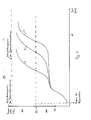
- curves for different water loads of the adsorbent are shown in Figure 1.
- curve 2 shows the temperature course of the adsorbent during regeneration with an average water load of the adsorbent.
- the temperature range depends on the type of adsorbent.
- the temperature range for molecular sieves is approx. 80 to 100 ° C. If the water is largely removed from the adsorbent, the temperature rises again faster, in order to finally approach the upper temperature of the inlet temperature of the regeneration medium, i.e. the hot air.
- the time required from the start of regeneration to reaching a predetermined temperature TE is a measure of the water load of the adsorbent.
- the time period which elapses from the start of the regeneration until the temperature TE of the adsorbent is reached gives a measure of the moisture adsorbed in the adsorbent.
- the detected time period can then be used to control the length of the subsequent adsorption phase.
- the temperature TE is expediently determined depending on the adsorbent used, and should be somewhat higher than the temperature range in which the water load is expelled from the adsorbent mainly by evaporation, in the case of molecular sieves TE should therefore be approximately between 120 ° C and 140 ° C .
- the regeneration begins with different starting temperatures of the molecular sieve.
- TA is below the zone in which the water is preferably driven out, with molecular sieve as adsorbent e.g. at about 60 ° to 80 ° C.
- the water absorption capacity of the adsorbents decreases with increasing temperature.
- the dry air then has a less favorable, higher dew point.
- this deterioration in the dew point with increasing exhaust air temperature is acceptable, since a high exhaust air temperature is a consequence of a lower throughput of material to be dried. The less favorable dew point then still allows sufficient drying.
- the length of the adsorption time is reduced as a function of the increasing exhaust air temperature, so that the regeneration begins when the amount of adsorbed water is reduced.
- the amount of water permitted for a desired dew point can easily be determined by trial and error by measuring the dew point of the dry air as a function of the water load of the molecular sieve and the temperature of the exhaust air. Conversely, a higher water load can be allowed if the exhaust air temperature is particularly low.
- the length of the adsorption time is controlled as a function of the dew point of the dry air.
- the permissible dew point at which the adsorption time is ended is regulated according to the temperature of the exhaust air, i.e. increased with increasing exhaust air temperature and reduced with decreasing exhaust air temperature.
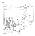
- drying air is supplied to a drying hopper 2 via a supply air line 14, which penetrates the bulk material (not shown) that sinks through the drying funnel 2, not shown, and is drawn off as moist air at the upper end of the drying funnel 2 via exhaust air line 3.
- the exhaust air line 3 opens into a drying pot 9 via a check valve 5, in which adsorbents 10, 11, for example silica gel and molecular sieve, are contained.
- the adsorbent 10, 11 extracts the entrained moisture from the moist exhaust air, so that the drying air leaving the drying pot 9 after warming up in one or both heaters 12, 13 is fed back to the drying judge 2 by a blower 1 via a further check valve 8 through the dry air line 14 . If the adsorbent 10, 11 is sufficiently moist is saturated, the direction of rotation of the fan 1 is reversed by a controller 20 so that the outside air is sucked in via a support 7a and a check valve 7, heated in the heater 12 and pressed through the drying pot 9. Through a nozzle 6a, the moist regeneration air is released into the open via a check valve 6 after the hot regeneration air has absorbed the adsorbed water from the adsorbent 10, 11.
- the switching times from drying the moist exhaust air from the drying hopper 2 to regenerating the adsorbent 10, 11 are determined by the controller 20.
- a temperature sensor 19 is provided, the probe of which projects into the outlet line 18 for moist regeneration air from the drying pot 9.
- the output signal of the temperature sensor 19 is fed to the controller 20 via a control signal line 17. This determines when the temperature TE in the outlet line 18 has been reached and then determines via control line 16 a switchover of the direction of rotation of the blower 1 and thus a switchover to moisture adsorption from the moist exhaust air from the drying hopper 2.
- the probe of the temperature sensor 19 could also be embedded in the part of the adsorbent 10 which is closest to the outlet channel 18.
- pressure load cells 24, 25 could be provided, on which the drying pot 9 is suspended and which record the weight loss of the drying pot 9 during regeneration. The output signals of the pressure transducers then reach control 20 via control signal line 17.
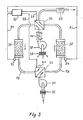
- FIG. 3 shows an embodiment of a device for drying moist gas, the basic features of which are known from US Pat. No. 4,038,054.
- a blower 31 draws in air laden with moisture through a filter 32 and presses it via a shuttle valve 33 into a first drying pot 35 filled with molecular sieve as adsorbent, in which the air passing through the adsorbent is carried by the entrained air Moisture is released.
- the dried air flows from the drying pot 35 via a further shuttle valve 34 and a heater 37 back to the consumer, for example a drying funnel.
- a blower 38 draws in regeneration air from the environment via a filter 39 and presses it through a heater 40 in which it is heated, and via the shuttle valve 34 through a second drying pot 36 filled with molecular sieve as the adsorbent.
- the heated regeneration air takes the im Adsorbent adsorbed moisture so that the moist regeneration air can be released into the environment via the shuttle valve 33 and a pipe socket 41.
- the changeover valves 33 and 34 are acted upon by control signals 55 and 57 from a controller 50 with changeover signals which cause the drying pots 35 and 36 to be switched from drying to regeneration and vice versa.
- the controller 50 is prompted to output the changeover signals by means of control signals on one of the control signal lines 51 or 53, which are output by temperature sensors 52, 54.
- the sensor of the temperature sensor 52 is located in the regeneration air outlet channel 59 between the drying pot 36 and the outlet port 41 in the position of the shuttle valves 33, 34 shown in FIG. 3.
- the sensor of the temperature sensor 54 is located in the regeneration air outlet channel 58 which, after the changeover of the valves 33 and 34 leads from the drying pot 35 to the outlet port 41.
- the controller 50 forms a reversing signal on lines 55 and 57 on the basis of a control signal from the temperature sensor 52 which is on line 51 and approximately represents the temperature TE only when the shuttle valves 33, 34 are switched, as shown in FIG. 3 .
- the controller 50 forms a reversal signal on lines 55 and 57 due to a control signal representing line TE, for example, on line 53 only when the shuttle valves 33 and 34 are changed over from the position shown in FIG. 3, so that the drying pot 35 is in the position shown in FIG Regeneration phase and the drying pot 36 are in the adsorption phase.
- the sensors of the temperature sensors 52 and 54 could also be inside the molecular sieve in the drying pots 34, 36 near the Outlet channels 58, 59 may be arranged.
- pressure load cells can be provided, on which the drying pots 35, 36 are mounted and record the decrease in weight of the drying pot 35 or 36 in the regeneration or adsorption process.
- the temperature sensor can be attached in a layer of the adsorbent itself, which is reached as late as possible by the hot air during the regeneration cycle.
- the temperature sensor can therefore be arranged essentially opposite the hot air inlet in the adsorbent.
- a drying pot contains 10 kg molecular sieve as adsorbent.
- the exhaust air is to be dried from a drying funnel through which the plastic granulate to be dried sinks.
- Under maximum load there is an optimal adsorption period of one hour during which 1 kg of water is adsorbed.
- the molecular sieve which can adsorb a maximum of 20% of its weight, still enables a dew point of - 30 ° C in the dry air, which can be fed back into the drying hopper.
- the weight increase of the drying pot during the adsorption phase is measured at an exhaust air temperature of 50 ° C. It is at a time of adsorption on regeneration of the Switched drying pot, at which the amount of water absorbed reaches 1 kg.
- the amount of water absorbed by the adsorbent is determined by weighing during the regeneration phase. If it turns out that about 500 g of water were released during the regeneration cycle, and consequently only 500 g of water were absorbed by the adsorbent in the previous adsorption phase, the controller doubles the subsequent adsorption time for the drying pot.
- the subsequent adsorptive period will be delayed by a fixed period e.g. Extended 10 minutes. This gradual increase in the duration of the subsequent adsorption phases is carried out until it can be determined that 1 kg of water has been released during the regeneration phase. If this amount of water is exceeded, the subsequent adsorption phase is shortened by 10 minutes. In this way, the alternation of adsorption and regeneration settles to an optimal adsorption length at which the absorption capacity of the adsorbent is practically fully utilized.
- a fixed period e.g. Extended 10 minutes.
Landscapes
- Chemical & Material Sciences (AREA)
- Engineering & Computer Science (AREA)
- Analytical Chemistry (AREA)
- General Chemical & Material Sciences (AREA)
- Oil, Petroleum & Natural Gas (AREA)
- Chemical Kinetics & Catalysis (AREA)
- Drying Of Gases (AREA)
- Drying Of Solid Materials (AREA)
Applications Claiming Priority (2)
| Application Number | Priority Date | Filing Date | Title |
|---|---|---|---|
| DE3901779 | 1989-01-21 | ||
| DE3901779A DE3901779C2 (de) | 1989-01-21 | 1989-01-21 | Verfahren und Vorrichtung zur Adsorption von Feuchtigkeit aus Gasen, insbesondere Luft |
Publications (3)
| Publication Number | Publication Date |
|---|---|
| EP0379975A2 true EP0379975A2 (fr) | 1990-08-01 |
| EP0379975A3 EP0379975A3 (en) | 1990-12-19 |
| EP0379975B1 EP0379975B1 (fr) | 1994-03-30 |
Family
ID=6372547
Family Applications (1)
| Application Number | Title | Priority Date | Filing Date |
|---|---|---|---|
| EP90101002A Expired - Lifetime EP0379975B1 (fr) | 1989-01-21 | 1990-01-18 | Procédé et positif pour l'adsorption de l'humidité à partir de gaz, en particulier de l'air |
Country Status (5)
| Country | Link |
|---|---|
| EP (1) | EP0379975B1 (fr) |
| JP (1) | JP3083827B2 (fr) |
| BR (1) | BR9000240A (fr) |
| DE (2) | DE3901779C2 (fr) |
| ES (1) | ES2054104T3 (fr) |
Cited By (6)
| Publication number | Priority date | Publication date | Assignee | Title |
|---|---|---|---|---|
| WO1991019566A1 (fr) | 1990-06-21 | 1991-12-26 | International Fuel Cells Corporation | Procede de production de catalyseurs en alliages |
| EP0658365A1 (fr) * | 1993-12-16 | 1995-06-21 | Praxair Technology, Inc. | Ajustage de systèmes d'adsorption à vide alterné |
| EP0712656A1 (fr) * | 1994-10-20 | 1996-05-22 | Roderich W. Dr. Graeff | Procédé et dispositif pour sécher des gaz humides |
| EP0848993A3 (fr) * | 1996-12-18 | 1999-08-04 | Ebara Corporation | Procédé d'évaluation de la performance d'un filtre chimique pour la purification d'un gaz |
| WO2004043574A1 (fr) | 2002-11-12 | 2004-05-27 | Alfred Wiedl | Installation pour secher ou deshydrater des produits |
| ITVI20100031A1 (it) * | 2010-02-12 | 2011-08-13 | Comem Spa | Procedimento per il controllo di un essiccatore atto a deumidificare l'aria destinata a vasi di espansione dell'olio impiegati in apparecchiature elettriche |
Families Citing this family (7)
| Publication number | Priority date | Publication date | Assignee | Title |
|---|---|---|---|---|
| EP0938360B1 (fr) * | 1996-10-31 | 2002-08-28 | ultrafilter international AG | Installation de sechage par adsorption et procede de verification fonctionelle |
| DE19726207B4 (de) * | 1997-06-20 | 2010-12-16 | Motan Holding Gmbh | Verfahren zum Regenerieren wenigstens eines Molekularsiebes |
| RU2190458C1 (ru) * | 2001-01-05 | 2002-10-10 | Курников Александр Серафимович | Установка адсорбционной осушки газов |
| WO2006069903A1 (fr) | 2004-12-23 | 2006-07-06 | Mann+Hummel Protec Gmbh | Procede pour secher des granules de matiere plastique |
| JP5931002B2 (ja) * | 2013-04-19 | 2016-06-08 | エクアールシー株式会社 | 低湿庫用乾燥装置 |
| JP6439157B2 (ja) * | 2014-10-16 | 2018-12-19 | シャープ株式会社 | 吸湿材、除湿装置及び除湿方法 |
| US12036637B2 (en) | 2018-04-24 | 2024-07-16 | Cold Jet, Llc | Particle blast apparatus |
Family Cites Families (3)
| Publication number | Priority date | Publication date | Assignee | Title |
|---|---|---|---|---|
| US2561441A (en) * | 1949-02-04 | 1951-07-24 | Cargocaire Engineering Corp | Control means for dehumidifying apparatus |
| DE2354745C2 (de) * | 1973-11-02 | 1985-09-05 | Roderich Wilhelm Dr.-Ing. 6100 Darmstadt Gräff | Vorrichtung zum Trocknen von Gas |
| DE3625013C2 (de) * | 1986-07-24 | 1995-05-24 | Somos Gmbh | Verfahren und Vorrichtung zum Trocknen von Schüttgut vorzugsweise aus Kunststoffgranulat |
-
1989
- 1989-01-21 DE DE3901779A patent/DE3901779C2/de not_active Expired - Lifetime
-
1990
- 1990-01-18 ES ES90101002T patent/ES2054104T3/es not_active Expired - Lifetime
- 1990-01-18 DE DE90101002T patent/DE59005143D1/de not_active Expired - Lifetime
- 1990-01-18 EP EP90101002A patent/EP0379975B1/fr not_active Expired - Lifetime
- 1990-01-22 JP JP02013455A patent/JP3083827B2/ja not_active Expired - Fee Related
- 1990-01-22 BR BR909000240A patent/BR9000240A/pt not_active IP Right Cessation
Cited By (11)
| Publication number | Priority date | Publication date | Assignee | Title |
|---|---|---|---|---|
| WO1991019566A1 (fr) | 1990-06-21 | 1991-12-26 | International Fuel Cells Corporation | Procede de production de catalyseurs en alliages |
| EP0658365A1 (fr) * | 1993-12-16 | 1995-06-21 | Praxair Technology, Inc. | Ajustage de systèmes d'adsorption à vide alterné |
| EP0712656A1 (fr) * | 1994-10-20 | 1996-05-22 | Roderich W. Dr. Graeff | Procédé et dispositif pour sécher des gaz humides |
| US5688305A (en) * | 1994-10-20 | 1997-11-18 | Graeff; Roderich Wilhelm | Method and device for drying of moist gases |
| EP0848993A3 (fr) * | 1996-12-18 | 1999-08-04 | Ebara Corporation | Procédé d'évaluation de la performance d'un filtre chimique pour la purification d'un gaz |
| US6009739A (en) * | 1996-12-18 | 2000-01-04 | Ebara Corporation | Method for evaluating performance of chemical filter for cleaning gas |
| WO2004043574A1 (fr) | 2002-11-12 | 2004-05-27 | Alfred Wiedl | Installation pour secher ou deshydrater des produits |
| AT412999B (de) * | 2002-11-12 | 2005-09-26 | Wiedl Alfred | Anlage zum trocknen von gütern |
| US7191547B2 (en) | 2002-11-12 | 2007-03-20 | Alfred Freh | Installation for drying or dehydrating goods |
| ITVI20100031A1 (it) * | 2010-02-12 | 2011-08-13 | Comem Spa | Procedimento per il controllo di un essiccatore atto a deumidificare l'aria destinata a vasi di espansione dell'olio impiegati in apparecchiature elettriche |
| WO2011099046A1 (fr) * | 2010-02-12 | 2011-08-18 | Abb S.P.A. | Procédé de commande de séchoir apte à déshumidifier l'air pénétrant dans les cuves d'expansion d'huile d'appareils électriques |
Also Published As
| Publication number | Publication date |
|---|---|
| EP0379975B1 (fr) | 1994-03-30 |
| BR9000240A (pt) | 1990-11-13 |
| DE3901779C2 (de) | 1997-08-14 |
| EP0379975A3 (en) | 1990-12-19 |
| DE3901779A1 (de) | 1990-08-02 |
| JPH02233121A (ja) | 1990-09-14 |
| ES2054104T3 (es) | 1994-08-01 |
| DE59005143D1 (de) | 1994-05-05 |
| JP3083827B2 (ja) | 2000-09-04 |
Similar Documents
| Publication | Publication Date | Title |
|---|---|---|
| EP0379975B1 (fr) | Procédé et positif pour l'adsorption de l'humidité à partir de gaz, en particulier de l'air | |
| DE3911574C2 (de) | Verfahren und Vorrichtung zum Trocknen oder Fraktionieren von Gas | |
| DE2746204C2 (de) | Verfahren und Vorrichtung zur Verringerung der Wasserdampfkonzentration in einem wasserdampfhaltigen Gas | |
| EP0712656B1 (fr) | Procédé et dispositif pour sécher des gaz humides | |
| DE3131471C2 (fr) | ||
| DE3625013C2 (de) | Verfahren und Vorrichtung zum Trocknen von Schüttgut vorzugsweise aus Kunststoffgranulat | |
| DE2806747C2 (de) | Verfahren und Vorrichtung zum Trocknen eines feuchtigkeitsaufnehmenden Materials | |
| DE69827876T2 (de) | Verfahren und Vorrichtung zur Regeneration eines feuchten Adsorptionsmediums | |
| EP0626244A1 (fr) | Procédé et dispositif pour la régénération d'adsorbeurs saturés d'humidité | |
| DE3336048C2 (de) | Verfahren und Vorrichtung zum Entfeuchten eines Trockengases | |
| DE1544105A1 (de) | Verfahren und Vorrichtung zum Herabsetzen der Konzentration eines Gases in Gemischen mit einem zweiten Gas | |
| DE4325915A1 (de) | Verfahren zum Messen einer Feuchte einer Warenbahn an einem Durchströmungstrockner und Vorrichtung zur Durchführung des Verfahrens | |
| EP2470713B1 (fr) | Procédé pour faire fonctionner un séchoir à adsorption et séchoir pour mettre en oeuvre le procédé | |
| AT510486B1 (de) | Verfahren zur trocknung und anlage zur durchführung des verfahrens | |
| DE2735568A1 (de) | Verfahren und vorrichtung zur adsorption von loesemitteldaempfen | |
| DE102006053379A1 (de) | Wäschetrockner und Verfahren zur Steuerung seines Trockengangs | |
| DE4317641C2 (de) | Verfahren zum Trocknen eines strömenden Gases | |
| DE102012223436A1 (de) | Haushalts-Wäschetrocknungsgerät mit Reinigungseinrichtung für Flusenfilter | |
| CH410788A (de) | Verfahren zur mehrstufigen Trocknung von Filtrationsrückständen in Scheibenfiltern | |
| DE102007056426A1 (de) | Dunstabzugshaube mit einer Sorptionseinheit zum Sorbieren von Feuchtigkeit und Verfahren zum Betreiben der Dunstabzugshaube | |
| DE3145921A1 (de) | Verfahren und vorrichtung zum trocknen | |
| DE102009001111A1 (de) | Verfahren zum Betreiben eines Adsorptionstrockners sowie entsprechender Adsorptionstrockner | |
| DE2745310A1 (de) | Verfahren und vorrichtung zur messung der durchlaessigkeit von filtermitteln | |
| DE2342397C2 (de) | Verfahren zum Entfernen eines ersten Bestandteiles aus einem aus mindestens drei Bestandteilen zusammengesetzten Gas | |
| DE19726207B4 (de) | Verfahren zum Regenerieren wenigstens eines Molekularsiebes |
Legal Events
| Date | Code | Title | Description |
|---|---|---|---|
| PUAI | Public reference made under article 153(3) epc to a published international application that has entered the european phase |
Free format text: ORIGINAL CODE: 0009012 |
|
| AK | Designated contracting states |
Kind code of ref document: A2 Designated state(s): DE ES FR GB IT |
|
| PUAL | Search report despatched |
Free format text: ORIGINAL CODE: 0009013 |
|
| AK | Designated contracting states |
Kind code of ref document: A3 Designated state(s): DE ES FR GB IT |
|
| 17P | Request for examination filed |
Effective date: 19910603 |
|
| 17Q | First examination report despatched |
Effective date: 19920730 |
|
| GRAA | (expected) grant |
Free format text: ORIGINAL CODE: 0009210 |
|
| RAP1 | Party data changed (applicant data changed or rights of an application transferred) |
Owner name: SOMOS GMBH |
|
| AK | Designated contracting states |
Kind code of ref document: B1 Designated state(s): DE ES FR GB IT |
|
| REF | Corresponds to: |
Ref document number: 59005143 Country of ref document: DE Date of ref document: 19940505 |
|
| ITF | It: translation for a ep patent filed | ||
| ET | Fr: translation filed | ||
| GBT | Gb: translation of ep patent filed (gb section 77(6)(a)/1977) |
Effective date: 19940609 |
|
| REG | Reference to a national code |
Ref country code: ES Ref legal event code: FG2A Ref document number: 2054104 Country of ref document: ES Kind code of ref document: T3 |
|
| PLBE | No opposition filed within time limit |
Free format text: ORIGINAL CODE: 0009261 |
|
| STAA | Information on the status of an ep patent application or granted ep patent |
Free format text: STATUS: NO OPPOSITION FILED WITHIN TIME LIMIT |
|
| 26N | No opposition filed | ||
| REG | Reference to a national code |
Ref country code: GB Ref legal event code: IF02 |
|
| PGFP | Annual fee paid to national office [announced via postgrant information from national office to epo] |
Ref country code: FR Payment date: 20060113 Year of fee payment: 17 |
|
| PGFP | Annual fee paid to national office [announced via postgrant information from national office to epo] |
Ref country code: GB Payment date: 20060120 Year of fee payment: 17 |
|
| PGFP | Annual fee paid to national office [announced via postgrant information from national office to epo] |
Ref country code: ES Payment date: 20060130 Year of fee payment: 17 |
|
| PGFP | Annual fee paid to national office [announced via postgrant information from national office to epo] |
Ref country code: IT Payment date: 20060131 Year of fee payment: 17 |
|
| GBPC | Gb: european patent ceased through non-payment of renewal fee |
Effective date: 20070118 |
|
| REG | Reference to a national code |
Ref country code: FR Ref legal event code: ST Effective date: 20070930 |
|
| PG25 | Lapsed in a contracting state [announced via postgrant information from national office to epo] |
Ref country code: GB Free format text: LAPSE BECAUSE OF NON-PAYMENT OF DUE FEES Effective date: 20070118 |
|
| REG | Reference to a national code |
Ref country code: ES Ref legal event code: FD2A Effective date: 20070119 |
|
| PG25 | Lapsed in a contracting state [announced via postgrant information from national office to epo] |
Ref country code: FR Free format text: LAPSE BECAUSE OF NON-PAYMENT OF DUE FEES Effective date: 20070131 |
|
| PG25 | Lapsed in a contracting state [announced via postgrant information from national office to epo] |
Ref country code: ES Free format text: LAPSE BECAUSE OF NON-PAYMENT OF DUE FEES Effective date: 20070119 |
|
| PGFP | Annual fee paid to national office [announced via postgrant information from national office to epo] |
Ref country code: DE Payment date: 20090122 Year of fee payment: 20 |
|
| PG25 | Lapsed in a contracting state [announced via postgrant information from national office to epo] |
Ref country code: IT Free format text: LAPSE BECAUSE OF NON-PAYMENT OF DUE FEES Effective date: 20070118 |
|
| PG25 | Lapsed in a contracting state [announced via postgrant information from national office to epo] |
Ref country code: DE Free format text: LAPSE BECAUSE OF EXPIRATION OF PROTECTION Effective date: 20100118 |