EP0379988A1 - Enceinte acoustique - Google Patents
Enceinte acoustique Download PDFInfo
- Publication number
- EP0379988A1 EP0379988A1 EP90101078A EP90101078A EP0379988A1 EP 0379988 A1 EP0379988 A1 EP 0379988A1 EP 90101078 A EP90101078 A EP 90101078A EP 90101078 A EP90101078 A EP 90101078A EP 0379988 A1 EP0379988 A1 EP 0379988A1
- Authority
- EP
- European Patent Office
- Prior art keywords
- loudspeaker
- chassis
- volume
- coupling
- chambers
- Prior art date
- Legal status (The legal status is an assumption and is not a legal conclusion. Google has not performed a legal analysis and makes no representation as to the accuracy of the status listed.)
- Granted
Links
Images


Classifications
-
- H—ELECTRICITY
- H04—ELECTRIC COMMUNICATION TECHNIQUE
- H04R—LOUDSPEAKERS, MICROPHONES, GRAMOPHONE PICK-UPS OR LIKE ACOUSTIC ELECTROMECHANICAL TRANSDUCERS; ELECTRIC HEARING AIDS; PUBLIC ADDRESS SYSTEMS
- H04R1/00—Details of transducers, loudspeakers or microphones
- H04R1/20—Arrangements for obtaining desired frequency or directional characteristics
- H04R1/22—Arrangements for obtaining desired frequency or directional characteristics for obtaining desired frequency characteristic only
- H04R1/28—Transducer mountings or enclosures modified by provision of mechanical or acoustic impedances, e.g. resonator, damping means
- H04R1/2807—Enclosures comprising vibrating or resonating arrangements
- H04R1/2838—Enclosures comprising vibrating or resonating arrangements of the bandpass type
- H04R1/2842—Enclosures comprising vibrating or resonating arrangements of the bandpass type for loudspeaker transducers
-
- H—ELECTRICITY
- H04—ELECTRIC COMMUNICATION TECHNIQUE
- H04R—LOUDSPEAKERS, MICROPHONES, GRAMOPHONE PICK-UPS OR LIKE ACOUSTIC ELECTROMECHANICAL TRANSDUCERS; ELECTRIC HEARING AIDS; PUBLIC ADDRESS SYSTEMS
- H04R1/00—Details of transducers, loudspeakers or microphones
- H04R1/20—Arrangements for obtaining desired frequency or directional characteristics
- H04R1/22—Arrangements for obtaining desired frequency or directional characteristics for obtaining desired frequency characteristic only
- H04R1/227—Arrangements for obtaining desired frequency or directional characteristics for obtaining desired frequency characteristic only using transducers reproducing the same frequency band
Definitions
- the invention relates to a loudspeaker box based on the acoustic bandpass principle with an outer housing, an inner baffle and a loudspeaker chassis attached to it.
- Loudspeakers are known according to different acoustic principles.
- An acoustic principle is the bandpass system, in which a defined frequency range can be emitted from an existing frequency spectrum solely by the housing construction and the arrangement of the loudspeaker chassis.
- loudspeaker boxes that work according to other acoustic principles, such as the closed box, the reflex system, etc., electrical or electronic crossovers are required to be able to radiate certain frequency ranges.
- a loudspeaker box based on the bandpass system is already known, in which a loudspeaker chassis is arranged within a housing and two separate chambers are provided.
- This speaker box is used in particular to emit the bass range with a frequency, for example, less than 500 Hertz.
- This loudspeaker is at a low frequency range comparatively large chamber volume and thus an overall correspondingly large outer housing is required.
- Such so-called "subwoofers” are used primarily in the sound reinforcement area of musicians or in studios and for hi-fi applications.
- the size of the loudspeaker box plays a significant role, since these usually have to be removed after the performance and have to be reassembled at another location. Even at the place of use, there is usually limited space, which often also does not allow optimal placement of large (bass) loudspeakers.
- the object of the present invention is to create a loudspeaker box of the type mentioned at the outset, which has a substantially reduced housing volume for a predetermined frequency range or which allows the frequency bandwidth to be increased while the housing volume remains the same. At the same time, the resilience of the loudspeaker box should be increased and the distortion reduced.
- the invention proposes in particular that at least two loudspeaker chassis connected acoustically in series via coupling volumes are provided, which operate acoustically in phase and that at least one of the chambers adjacent to the coupling volume or volumes has at least one reflex opening or the like. If, for example, two loudspeaker chassis are used, half of the housing volume is practically sufficient to achieve the same frequency response as with previous bandpass systems. At the same time, the electrical load capacity is doubled. The situation is similar when using more than two, for example three or four speakers.
- the arrangement according to the invention of at least two loudspeaker chassis also gives a filter characteristic of a higher order, as a result of which the steepness of the frequency response is increased and thus the efficiency for the respectively provided frequency range is improved.
- a particularly advantageous embodiment provides that an inner baffle with two loudspeaker chassis attached to it and enclosing a coupling volume is provided.
- This embodiment has the advantage that good acoustic data and practically halved housing volume can be used with little effort overall, since only two loudspeaker chassis are used here.
- the two loudspeakers are arranged with their membrane front sides facing one another.
- the coupling volume is formed between the front sides of the membrane, the membranes forming the boundary walls.
- the arrangement of several loudspeakers according to the invention enables the distortions that occur to be reduced even further. It is expediently provided that the chamber volumes and / or the reflex openings are different and that two identical loudspeaker chassis are provided. This significantly simplifies production, since two identical loudspeaker systems can be used, and also the tuning of the chamber or the overall loudspeaker box is considerably simplified, since the chamber volume and / or the reflex openings can be changed easily. On the other hand, be However, there is also the possibility of designing the chamber volumes and / or the reflex openings approximately the same, and then providing two loudspeaker chassis with different electro-acoustic parameters. In this case, different and adapted speakers must be used accordingly.
- the coupling volume or volumes is expediently sealed off from adjacent chambers or from adjacent coupling volumes. This dense coupling volume contributes to a largely "rigid" coupling of the two systems, so that the distortions that occur can be kept comparatively small.
- a modified embodiment of the invention provides that several inner baffles, each with one or more loudspeaker chassis attached to it, are provided. This enables a further reduction in the housing volume with the same frequency response. This also gives the loudspeaker an even higher load capacity.
- both chambers each have at least one reflex opening.
- a bandpass system of a higher order is obtained with a bandpass system with two chambers and reflex openings provided there.
- a loudspeaker box shown in FIGS. 1 and 2 has an outer housing 2 in which there is an inner baffle 3 with loudspeaker chassis 4, 4a attached to it.
- the inner baffle 3 separates two chambers 5, 5a located within the housing 2, each of which is connected to the outside area by a reflex opening 7 or 7a on the front 9 of the loudspeaker box.
- the reflex openings 7, 7a can be formed by housing wall openings, and in variant embodiments, tunnel openings with an extended passage channel can also be provided here.
- the size of the reflex openings 7, 7a and also their special design, possibly with a tunnel or the like, are used to coordinate the loudspeaker box 1. It can be clearly seen in the figures that the chamber volumes are different.
- the same loudspeaker chassis are used here, so that different acoustic data are obtained through the different chamber volumes, which determine the lower and the upper corner frequency of the bandpass filter.
- the reflex openings are accordingly designed differently, the smaller-volume chamber having the larger reflex opening 7 and the other chamber 5a having the smaller reflex opening 7a.
- the two loudspeaker chassis 4, 4a are arranged with their membrane front sides 8 facing one another and, with their membranes, delimit a coupling volume 6 located between them. This coupling volume 6 is opposed by the membranes tightly sealed above the respective chamber volume.
- the loudspeaker chassis are connected acoustically in series and work acoustically in phase, so that the membranes are deflected parallel to one another.
- the arrangement of the loudspeaker chassis shown with mutually facing diaphragm front sides enables particularly simple assembly and also results in the smallest possible coupling volume 6.
- This smallest possible coupling volume is aimed at on the one hand to keep the overall volume of the loudspeaker box small and on the other hand to avoid the distortion of the individual loudspeaker systems due to being as rigid as possible To largely compensate coupling via a small coupling volume. Measurements have shown that the harmonic distortion is approx. 10 dB lower than when using bandpass loudspeakers with a chassis that were previously common.
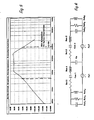
- FIG. 5 shows the frequency response of a bandpass loudspeaker box according to FIGS. 1 and 2 simulated with the aid of a computer.
- the ordinate shows the sound pressure in decibels and the abscissa the frequency.
- the -3 dB line results in a frequency range from approximately 40 Hertz to approximately 220 Hertz. Since the loudspeaker box according to the invention is a higher-order bandpass system, the edges of the frequency transmission range are accordingly correspondingly steeper than in the case of systems customary hitherto.
- This network gives a tenth order transfer function.
- This analog circuit diagram also shows that when two identical loudspeaker chassis are used, the housing volume is halved.
- FIG. 3 shows a bandpass loudspeaker box 1a, which has four inner baffles 3, each with a loudspeaker chassis 4 attached to it.
- the coupling volumes 6 are located here between these inner baffles 3.
- the load capacity is four times higher.
- FIG. 4 shows a bandpass loudspeaker box 1b with four acoustically series-connected loudspeaker chassis 4, 4a, 4b, 4c, three coupling volumes 6 and only one chamber 5 with a reflex opening 7 being provided here.
- the loudspeaker chassis used work acoustically in phase, the membranes being deflected practically parallel in the same direction.
- the bandpass loudspeaker according to the invention made it possible to achieve significant improvements with regard to the following requirements: - Significant reduction in the volume of the housing, - increasing the sound pressure, - largely distortion-free bass reproduction, - Use with other systems without the use of crossovers, - frequency range about 50 to 200 Hertz, - low manufacturing price.
- the loudspeaker chassis 4, 4a facing each other in FIGS. 1 and 2 with their membrane front sides 8 can also be arranged on the inner baffle 3 facing away from one another. In this case, a corresponding sealing of the coupling volume 6 located between them, which is then delimited by the membrane backs, must be provided.
Landscapes
- Health & Medical Sciences (AREA)
- Otolaryngology (AREA)
- Physics & Mathematics (AREA)
- Engineering & Computer Science (AREA)
- Acoustics & Sound (AREA)
- Signal Processing (AREA)
- Details Of Audible-Bandwidth Transducers (AREA)
- Obtaining Desirable Characteristics In Audible-Bandwidth Transducers (AREA)
- Fittings On The Vehicle Exterior For Carrying Loads, And Devices For Holding Or Mounting Articles (AREA)
- Audible-Bandwidth Dynamoelectric Transducers Other Than Pickups (AREA)
Applications Claiming Priority (2)
| Application Number | Priority Date | Filing Date | Title |
|---|---|---|---|
| DE3902343A DE3902343A1 (de) | 1989-01-27 | 1989-01-27 | Lautsprecherbox |
| DE3902343 | 1989-01-27 |
Publications (2)
| Publication Number | Publication Date |
|---|---|
| EP0379988A1 true EP0379988A1 (fr) | 1990-08-01 |
| EP0379988B1 EP0379988B1 (fr) | 1994-07-13 |
Family
ID=6372871
Family Applications (1)
| Application Number | Title | Priority Date | Filing Date |
|---|---|---|---|
| EP90101078A Revoked EP0379988B1 (fr) | 1989-01-27 | 1990-01-19 | Enceinte acoustique |
Country Status (4)
| Country | Link |
|---|---|
| EP (1) | EP0379988B1 (fr) |
| AT (1) | ATE108597T1 (fr) |
| DE (2) | DE3902343A1 (fr) |
| ES (1) | ES2058613T3 (fr) |
Cited By (1)
| Publication number | Priority date | Publication date | Assignee | Title |
|---|---|---|---|---|
| US5771302A (en) * | 1996-05-09 | 1998-06-23 | Nokai Technology Gmbh | Subwoofer--loudspeaker box |
Families Citing this family (1)
| Publication number | Priority date | Publication date | Assignee | Title |
|---|---|---|---|---|
| DE19734120A1 (de) * | 1997-08-07 | 1999-02-18 | Nokia Deutschland Gmbh | Tonwiedergabeanordnung |
Citations (2)
| Publication number | Priority date | Publication date | Assignee | Title |
|---|---|---|---|---|
| US4016953A (en) * | 1975-05-23 | 1977-04-12 | Butler Robert J | Push-pull transducer system |
| DE2906002A1 (de) * | 1979-02-16 | 1980-02-21 | Hans Deutsch Akustikforschung | Lautsprecheranordnung |
Family Cites Families (4)
| Publication number | Priority date | Publication date | Assignee | Title |
|---|---|---|---|---|
| DE1728058A1 (de) * | 1968-08-20 | 1972-03-23 | Bauer Carl Fa | Verfahren zum Befestigen von insbesondere bruchempfindlichen Gegenstaenden mit einem Bolzensetzwerkzeug |
| GB1500711A (en) * | 1974-01-26 | 1978-02-08 | Tiefenbrun I | Loudspeaker systems |
| FR2338616A1 (fr) * | 1976-01-16 | 1977-08-12 | Leon Joseph | Emetteur de son |
| DE2837520A1 (de) * | 1978-08-28 | 1980-03-27 | Harald Schuster | Lautsprecher, passiv servokontrolliert mit korrektur der phasendrehung |
-
1989
- 1989-01-27 DE DE3902343A patent/DE3902343A1/de not_active Ceased
-
1990
- 1990-01-19 EP EP90101078A patent/EP0379988B1/fr not_active Revoked
- 1990-01-19 AT AT90101078T patent/ATE108597T1/de active
- 1990-01-19 DE DE59006384T patent/DE59006384D1/de not_active Expired - Fee Related
- 1990-01-19 ES ES90101078T patent/ES2058613T3/es not_active Expired - Lifetime
Patent Citations (2)
| Publication number | Priority date | Publication date | Assignee | Title |
|---|---|---|---|---|
| US4016953A (en) * | 1975-05-23 | 1977-04-12 | Butler Robert J | Push-pull transducer system |
| DE2906002A1 (de) * | 1979-02-16 | 1980-02-21 | Hans Deutsch Akustikforschung | Lautsprecheranordnung |
Cited By (1)
| Publication number | Priority date | Publication date | Assignee | Title |
|---|---|---|---|---|
| US5771302A (en) * | 1996-05-09 | 1998-06-23 | Nokai Technology Gmbh | Subwoofer--loudspeaker box |
Also Published As
| Publication number | Publication date |
|---|---|
| EP0379988B1 (fr) | 1994-07-13 |
| DE3902343A1 (de) | 1990-08-02 |
| ES2058613T3 (es) | 1994-11-01 |
| ATE108597T1 (de) | 1994-07-15 |
| DE59006384D1 (de) | 1994-08-18 |
Similar Documents
| Publication | Publication Date | Title |
|---|---|---|
| DE69119376T2 (de) | Lautsprechersystem mit mehreren Unterkammern | |
| DE69122908T2 (de) | Anordnung von Lautsprechern im Gehäuse eines Fernsehempfängers | |
| DE4446690B4 (de) | Lautsprecheranordnung | |
| DE2815051C2 (de) | Kopfhörer in geschlossener Bauweise | |
| EP0125625A1 (fr) | Enceinte pour haut-parleur avec filtre passe-bande incorporé | |
| DE3410134A1 (de) | Lautsprecher-system mit einem mit mehreren schalloeffnungen versehenen gehaeuse | |
| EP0154219B1 (fr) | Dispositif de reproduction de son stéréophonique pour récepteur de télévision | |
| DE3148070A1 (de) | Lautsprechersystem | |
| DE102006058009B3 (de) | Lautsprechersystem mit reduzierter rückseitiger Schallabstrahlung | |
| DE3818366A1 (de) | Lautsprecheranlage | |
| DE69736941T2 (de) | Lautsprechervorrichtung | |
| EP0896497B1 (fr) | Système de reproduction de son | |
| EP0379988B1 (fr) | Enceinte acoustique | |
| EP2158789B1 (fr) | Dispositif à membrane pour transformateur de mouvement d'air, et transducteur acoustique présentant un tel dispositif à membrane | |
| DE2802973A1 (de) | Lautsprecher | |
| DE102020121725A1 (de) | Koaxiallautsprecher | |
| DE3144545A1 (de) | Lautsprechersystem | |
| EP0692922B1 (fr) | Enceinte acoustique pour haut-parleur basse-fréquence | |
| DE2552591C3 (de) | Prinzip eines Lautsprechergehäuses für den Tieftonbereich | |
| DE2851876A1 (de) | Stereophone lautsprecheranordnung fuer ein fahrzeug | |
| DE3707232A1 (de) | Lautsprecherbox mit mehrfach-frequenzweiche | |
| DE2729051A1 (de) | Lautsprechersystem | |
| DE3918654C2 (fr) | ||
| DE3443690C2 (fr) | ||
| DE69421995T2 (de) | Lautsprechergehäuse mit erweiterter Diffusion |
Legal Events
| Date | Code | Title | Description |
|---|---|---|---|
| PUAI | Public reference made under article 153(3) epc to a published international application that has entered the european phase |
Free format text: ORIGINAL CODE: 0009012 |
|
| AK | Designated contracting states |
Kind code of ref document: A1 Designated state(s): AT CH DE ES FR IT LI NL SE |
|
| 17P | Request for examination filed |
Effective date: 19910129 |
|
| 17Q | First examination report despatched |
Effective date: 19930401 |
|
| GRAA | (expected) grant |
Free format text: ORIGINAL CODE: 0009210 |
|
| AK | Designated contracting states |
Kind code of ref document: B1 Designated state(s): AT CH DE ES FR IT LI NL SE |
|
| REF | Corresponds to: |
Ref document number: 108597 Country of ref document: AT Date of ref document: 19940715 Kind code of ref document: T |
|
| REF | Corresponds to: |
Ref document number: 59006384 Country of ref document: DE Date of ref document: 19940818 |
|
| ET | Fr: translation filed | ||
| ITF | It: translation for a ep patent filed | ||
| REG | Reference to a national code |
Ref country code: ES Ref legal event code: FG2A Ref document number: 2058613 Country of ref document: ES Kind code of ref document: T3 |
|
| EAL | Se: european patent in force in sweden |
Ref document number: 90101078.5 |
|
| PLBI | Opposition filed |
Free format text: ORIGINAL CODE: 0009260 |
|
| 26 | Opposition filed |
Opponent name: INTERESSENGEMEINSCHAFT FUER RUNDFUNKSCHUTZRECHTE E Effective date: 19950413 |
|
| NLR1 | Nl: opposition has been filed with the epo |
Opponent name: INTERESSENGEMEINSCHAFT FUER RUNDFUNKSCHUTZRECHTE E |
|
| PGFP | Annual fee paid to national office [announced via postgrant information from national office to epo] |
Ref country code: FR Payment date: 19960130 Year of fee payment: 7 |
|
| PGFP | Annual fee paid to national office [announced via postgrant information from national office to epo] |
Ref country code: SE Payment date: 19960131 Year of fee payment: 7 Ref country code: NL Payment date: 19960131 Year of fee payment: 7 Ref country code: ES Payment date: 19960131 Year of fee payment: 7 Ref country code: AT Payment date: 19960131 Year of fee payment: 7 |
|
| PGFP | Annual fee paid to national office [announced via postgrant information from national office to epo] |
Ref country code: CH Payment date: 19960212 Year of fee payment: 7 |
|
| PG25 | Lapsed in a contracting state [announced via postgrant information from national office to epo] |
Ref country code: AT Effective date: 19970119 |
|
| PG25 | Lapsed in a contracting state [announced via postgrant information from national office to epo] |
Ref country code: SE Effective date: 19970120 Ref country code: ES Free format text: LAPSE BECAUSE OF NON-PAYMENT OF DUE FEES Effective date: 19970120 |
|
| PGFP | Annual fee paid to national office [announced via postgrant information from national office to epo] |
Ref country code: DE Payment date: 19970120 Year of fee payment: 8 |
|
| PG25 | Lapsed in a contracting state [announced via postgrant information from national office to epo] |
Ref country code: LI Free format text: LAPSE BECAUSE OF NON-PAYMENT OF DUE FEES Effective date: 19970131 Ref country code: CH Free format text: LAPSE BECAUSE OF NON-PAYMENT OF DUE FEES Effective date: 19970131 |
|
| PG25 | Lapsed in a contracting state [announced via postgrant information from national office to epo] |
Ref country code: NL Effective date: 19970801 |
|
| REG | Reference to a national code |
Ref country code: CH Ref legal event code: PL |
|
| PG25 | Lapsed in a contracting state [announced via postgrant information from national office to epo] |
Ref country code: FR Effective date: 19970930 |
|
| NLV4 | Nl: lapsed or anulled due to non-payment of the annual fee |
Effective date: 19970801 |
|
| EUG | Se: european patent has lapsed |
Ref document number: 90101078.5 |
|
| REG | Reference to a national code |
Ref country code: FR Ref legal event code: ST |
|
| PG25 | Lapsed in a contracting state [announced via postgrant information from national office to epo] |
Ref country code: DE Free format text: LAPSE BECAUSE OF NON-PAYMENT OF DUE FEES Effective date: 19981001 |
|
| RDAH | Patent revoked |
Free format text: ORIGINAL CODE: EPIDOS REVO |
|
| RDAG | Patent revoked |
Free format text: ORIGINAL CODE: 0009271 |
|
| STAA | Information on the status of an ep patent application or granted ep patent |
Free format text: STATUS: PATENT REVOKED |
|
| 27W | Patent revoked |
Effective date: 19981026 |