EP0380232A2 - Strangpressdüse zum Extrudieren von Wabenstrukturen mit verdickter Aussenhaut - Google Patents
Strangpressdüse zum Extrudieren von Wabenstrukturen mit verdickter Aussenhaut Download PDFInfo
- Publication number
- EP0380232A2 EP0380232A2 EP90300468A EP90300468A EP0380232A2 EP 0380232 A2 EP0380232 A2 EP 0380232A2 EP 90300468 A EP90300468 A EP 90300468A EP 90300468 A EP90300468 A EP 90300468A EP 0380232 A2 EP0380232 A2 EP 0380232A2
- Authority
- EP
- European Patent Office
- Prior art keywords
- die
- mask
- assembly
- forming plate
- lip
- Prior art date
- Legal status (The legal status is an assumption and is not a legal conclusion. Google has not performed a legal analysis and makes no representation as to the accuracy of the status listed.)
- Granted
Links
Images


Classifications
-
- C—CHEMISTRY; METALLURGY
- C03—GLASS; MINERAL OR SLAG WOOL
- C03B—MANUFACTURE, SHAPING, OR SUPPLEMENTARY PROCESSES
- C03B19/00—Other methods of shaping glass
- C03B19/06—Other methods of shaping glass by sintering, e.g. by cold isostatic pressing of powders and subsequent sintering, by hot pressing of powders, by sintering slurries or dispersions not undergoing a liquid phase reaction
-
- B—PERFORMING OPERATIONS; TRANSPORTING
- B28—WORKING CEMENT, CLAY, OR STONE
- B28B—SHAPING CLAY OR OTHER CERAMIC COMPOSITIONS; SHAPING SLAG; SHAPING MIXTURES CONTAINING CEMENTITIOUS MATERIAL, e.g. PLASTER
- B28B3/00—Producing shaped articles from the material by using presses; Presses specially adapted therefor
- B28B3/20—Producing shaped articles from the material by using presses; Presses specially adapted therefor wherein the material is extruded
- B28B3/26—Extrusion dies
- B28B3/269—For multi-channeled structures, e.g. honeycomb structures
-
- B—PERFORMING OPERATIONS; TRANSPORTING
- B29—WORKING OF PLASTICS; WORKING OF SUBSTANCES IN A PLASTIC STATE IN GENERAL
- B29C—SHAPING OR JOINING OF PLASTICS; SHAPING OF MATERIAL IN A PLASTIC STATE, NOT OTHERWISE PROVIDED FOR; AFTER-TREATMENT OF THE SHAPED PRODUCTS, e.g. REPAIRING
- B29C48/00—Extrusion moulding, i.e. expressing the moulding material through a die or nozzle which imparts the desired form; Apparatus therefor
- B29C48/03—Extrusion moulding, i.e. expressing the moulding material through a die or nozzle which imparts the desired form; Apparatus therefor characterised by the shape of the extruded material at extrusion
- B29C48/09—Articles with cross-sections having partially or fully enclosed cavities, e.g. pipes or channels
- B29C48/11—Articles with cross-sections having partially or fully enclosed cavities, e.g. pipes or channels comprising two or more partially or fully enclosed cavities, e.g. honeycomb-shaped
-
- B—PERFORMING OPERATIONS; TRANSPORTING
- B29—WORKING OF PLASTICS; WORKING OF SUBSTANCES IN A PLASTIC STATE IN GENERAL
- B29D—PRODUCING PARTICULAR ARTICLES FROM PLASTICS OR FROM SUBSTANCES IN A PLASTIC STATE
- B29D99/00—Subject matter not provided for in other groups of this subclass
- B29D99/0089—Producing honeycomb structures
-
- B—PERFORMING OPERATIONS; TRANSPORTING
- B29—WORKING OF PLASTICS; WORKING OF SUBSTANCES IN A PLASTIC STATE IN GENERAL
- B29L—INDEXING SCHEME ASSOCIATED WITH SUBCLASS B29C, RELATING TO PARTICULAR ARTICLES
- B29L2031/00—Other particular articles
- B29L2031/60—Multitubular or multicompartmented articles, e.g. honeycomb
Definitions
- This invention relates to an extrusion die assembly for forming honeycomb structures from extrudable materials such as glass, glass-ceramics, ceramics, plastics, metals, cermets and other materials, especially those in particulate form, which are capable of being extruded through relatively small feed holes or channels whose length is several times their diameter or transverse dimension.
- the outlet ends of the feed holes communicate with grid forming discharge slots, these slots forming the cell walls of a honeycomb form extrudate.
- the honeycomb is treated to produce a rigid honeycomb structure as is known in this art.
- Thin-walled honeycomb structures display utility in a variety of technologies.
- thin-walled honeycomb structures fashioned from ceramic materials are used as catalyst carriers in catalytic converters in the exhaust system of internal combustion engines. They also are employed as radiators, catalyst carriers, filters, diesel particulate filters, molten metal filters, woodstove combustor substrates, and heat exchangers.
- This invention more specifically relates to an extrusion die assembly for producing a thickened skin or thickened outer wall on the surface of the extruded honeycomb structure.
- the external surface of the extrudate is defined by elongated ridges, the individual ridges being the exposed outer walls of the outermost honeycomb passageways of the fasces-like extruded structure or extrudate.
- the thickness of the outer surface is merely the wall thickness of the individual honeycomb passageways which form the elongated ridges. Workers in this art have recognized that the mechanical strength of the extrudate can be increased by modifying the extrusion process so that the extruded structure will have a thickened outer surface or skin so as to be thicker than the honeycomb cell walls.
- This is usually effected by deforming or crushing the elongated honeycomb cells at the periphery of the extrudate as the extrudate emerges from the die.
- This has been done by providing a ring with a radially inwardly extending lip, the lip distorting or changing the axial output direction of the flowable material passing through the periphery of the die discharge slots.
- the ring is often spaced from the face of the discharge slots by a shim, the region between the lip, shim and discharge slots forming a shim reservoir for the batch material being extruded.
- Such a ring is often termed a mask.
- a backer plate and flow diverter have also been used, the latter two elements being positioned on the inlet or upstream side of the die.
- the mask, the die, the shim and other elements being referred to herein as an extrusion die assembly.
- a forming plate is positioned at the input or upstream face of the die, the forming plate having a central opening congruent with the cross sectional shape of the extruded structure.
- the output or downstream region of the apparatus is provided, conventionally, with a mask and skin.
- a plurality of flow controlling openings extend through the forming plate and are located radially outwardly of the edge of the forming plate central opening.
- the die discharge slots which are axially aligned with the flow controlling openings may optionally be widened, so that the batch material passing through those die feed holes which are axially aligned with the flow controlling openings passes into the widened discharge slot region and thence into the skin forming region at the periphery of the die discharge slots.
- this invention is directed toward an extrusion die assembly for extruding a structure having a thickened outer skin, the assembly including an extrusion die having a plurality of axially extending and generally parallel feedholes, the die having an inlet face and an outlet face, the outlet face having a plurality of discharge slots, the latter being associated with by rows and columns of axially extending pins integral with the die, characterized by, a die mask at the periphery of the discharge end of the die, the mask having a radially inwardly extending lip axially spaced downstream from the ends of said pins and overlying an annularly continuous peripheral region of the die outlet face, said mask lip having an edge, said mask lip exerting a radially inwardly directed force on the extruded material passing through the central portion of the die to thereby form a thickened skin on the material being extruded, a forming plate positioned over the die inlet face and in surface contact therewith, said forming plate having a central opening congruent with
- the flow controlling openings which may be groove shaped or slots as well as holes, in the above assembly can be the same, larger, smaller, and/or a combination of sizes in relation to the feedholes.
- the invention is directed to an extrusion die assembly for extruding a structure having a thickened outer skin
- the assembly including an extrusion die having a plurality of axially extending and generally parallel feedholes, the die having an inlet face and an outlet face, the outlet face having a plurality of discharge slots, the latter being associated with rows and columns of axially extending pins integral with the die, characterized by, a die mask at the periphery of the discharge end of the die, the mask having a radially inwardly extending lip axially spaced downstream from the ends of said pins and overlying a peripheral region of the die outlet face, said mask lip projection having an edge, said mask lip exerting a radially inwardly directed force on the extruded material passing through the central portion of the die to thereby form a thickened skin on the batch material being extruded, means for independently controlling the volume and rate of flow of material which flows in a downstream direction towards and beneath said mask lip and which forms a thickened
- the present assembly permits a greater degree of separation of the volume of flow to the skin forming portions from the volume of flow to the main or radially central portion of the extrudate.
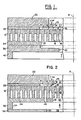
- the numeral 12 denotes a die, usually metal, having a lower or inlet face and an upper or outlet face.
- the upper face is provided with a plurality of integral pins 14 associated with a plurality of criss crossing slots 16 which define the usual batch material discharge slots.
- the die 12 is provided with a plurality of axially extending feed holes 18 which feed corresponding discharge slots 16.
- the numeral 22 denotes a mask having a radially inwardly extending lip or projection 24, the latter having an edge 26 of an opening 27, which may have an annular configuration.
- the numeral 28 denotes a shim for spacing the mask from the free or upper ends of the pins 14.
- the numeral 34 denotes a backer plate placed against the input surface of the die 12.
- the numeral 36 denotes a flow diverter plate having a radially inwardly extending portion terminating in a free edge 38 and a second radially inwardly extending portion 40.
- the axis 8 denotes the central longitudinal axis of the assembly, the axis running parallel to the central or main batch flow. The downstream portion of the assembly is here shown as above the upstream portion.
- the batch material is fed as indicated by the curved arrows into the feed holes.
- the material then exits through the discharge slots 16 and thence through orifice 27, with that portion of the batch discharge which is near the periphery of the extrudate being supplied from shim reservoir 30, which may be annular.
- the overhanging portion 24 of the mask 22 and the shim both compel the radially outermost portion of the batch material discharge to pass in the direction shown by the curved arrow at the discharge end of the discharge slots. This forms a thickened outer skin of the honeycomb extrudate.
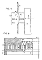
- a forming plate shown in plan view at Figure 3
- the forming plate is denoted by the numeral 44 and includes a series of flow controlling openings 46, which may vary in diameter relative to feed-holes 18 and may be arranged in an annular manner. These openings are positioned radially outwardly of the rim 48 of an opening 50 in the forming plate.
- the shape of the opening 50 is congruent with the transverse cross sectional shape of the honeycomb extrudate produced by the assembly.
- An elliptical shape is illustrated in Figure 3.
- the diameter of holes 46 is in the range of 0.02 to 0.25 inches, with the preferred range being 0.063 to 0.086 inches.
- each flow controlling hole 46 of forming plate 44 feeds at least one feed hole 18 of die 12.
- the function of the forming plate 44 and its openings 46 is to meter or control the volume of the batch material which reaches shim reservoir 30. From a consideration of Figure 1, it is seen that the volume of batch material in shim reservoir 30 is dependent on the extent of the radial overhang of mask 22 over shim reservoir 30. The rate of flow of the batch material through the die and this shim volume determines the character of the thickened skin of the honeycomb extrudate.
- the forming plate 44 and its openings 46 the volume of the batch material reaching the shim reservoir is separated from the main mass (flowing parallel to axis 8) of the batch material, the latter passing through opening 50 of the forming plate.
- the number of openings 46, their radial spacing from the rim 48 of opening 50, their diameter can all be employed to determine the volume and the rate of flow of material fed to shim reservoir 30.
- the diameter of openings 46 may be enlarged so that each feeds more than one die passageway or feed hole 18 of die 12.
- the diameter of openings 46 may vary one from the next adjacent. Such variation will depend on the number of cells per square inch/centimeter of the substrate, the cell thickness, and the shape of openings 46 which may assume the form of slots instead of circular holes. Each of these variables makes possible some degree of separation of the flow volume and flow rate of the skin forming batch material from the main or radially central flow volume and flow rate of the batch material.
- a shim 52 having an inward radial edge 54 is positioned below and against forming plate 44. Shim 52 spaces flow restrictor plate 56, having a central opening 58, from forming plate 44.
- the rim of opening 58 is denoted by 60.
- Recesses 61 may be provided at the ends of the major axis of elliptical opening 58, as shown at Figure 4.
- the use of flow restrictor plate 56 is optional and can be used to correct for unequal batch flow created by composition or the extruding apparatus, the latter indicated schematically by 57 at Figure 5.
- the batch feeding velocity can vary depending on viscosity of the batch material, condition of the extruding machine, and size and cell structure of the extruded body.
- the function of the flow restrictor is to equalize the batch flow before it reaches the forming plate/feedhole die.
- the restrictor plate will encourage batch flow or speed in one area and decrease batch flow in other areas, see Figures 4 and 5. What is intended is to provide equal batch flow or speed once it exits the flow restrictor.
- the design is dependent on extruding apparatus design, viscosity of the extruding material, and cell structure of the extruded body.
- Edge 60 of restrictor 56 is varied in particular areas, such as 61, to address and correct unequal velocities generated by a specific extruding apparatus 57.
- the restrictor plate will correct for such unequal velocities, as indicated by a velocity distribution curve 70.
- the unequal velocities are smoothed, as indicated by velocity distribution curve 72 of Figure 5.
- the need for skin thickness 3 to 20 times the web thickness is required.
- the no shim apparatus shown in Fig. 6 is employed.
- mask 22 remains a constant size, but can also be varied.
- the desired skin thickness is the relationship between edge 26 of the mask 22 and reservoir 32.
- those regions 14 between the discharge slots 16 which are axially aligned with the flow controlling openings 44 can be removed, as by plunge electric discharge machining (EDM), a technique known in this art.
- EDM plunge electric discharge machining
- the removed annular region 32 of the discharge slots is usually of a cross sectional width greater than the width of the discharge slots 16.
- Openings 46 can be funnel shaped, with the wider ends aligned with and feeding feed holes 18.
- the forming plate 44 is used to control batch flow to reservoir 32 with edge 46 of forming plate 42 being used to control cell distortion around the peripheral section of the honeycomb structure. If edge 26 size is radially increased, the skin will thicken, if edge 26 is radially decreased, the skin will be thinner.
Landscapes
- Engineering & Computer Science (AREA)
- Chemical & Material Sciences (AREA)
- Mechanical Engineering (AREA)
- Manufacturing & Machinery (AREA)
- Organic Chemistry (AREA)
- Materials Engineering (AREA)
- Dispersion Chemistry (AREA)
- Ceramic Engineering (AREA)
- Press-Shaping Or Shaping Using Conveyers (AREA)
- Extrusion Moulding Of Plastics Or The Like (AREA)
- Extrusion Of Metal (AREA)
- Laminated Bodies (AREA)
- Coating Apparatus (AREA)
Applications Claiming Priority (2)
| Application Number | Priority Date | Filing Date | Title |
|---|---|---|---|
| US302013 | 1989-01-26 | ||
| US07/302,013 US4915612A (en) | 1989-01-26 | 1989-01-26 | Extrusion die assembly for forming honeycomb structures having thickened outer skin |
Publications (3)
| Publication Number | Publication Date |
|---|---|
| EP0380232A2 true EP0380232A2 (de) | 1990-08-01 |
| EP0380232A3 EP0380232A3 (de) | 1991-01-16 |
| EP0380232B1 EP0380232B1 (de) | 1996-07-03 |
Family
ID=23165884
Family Applications (1)
| Application Number | Title | Priority Date | Filing Date |
|---|---|---|---|
| EP90300468A Expired - Lifetime EP0380232B1 (de) | 1989-01-26 | 1990-01-17 | Strangpressdüse zum Extrudieren von Wabenstrukturen mit verdickter Aussenhaut |
Country Status (6)
| Country | Link |
|---|---|
| US (1) | US4915612A (de) |
| EP (1) | EP0380232B1 (de) |
| JP (1) | JP2914507B2 (de) |
| KR (1) | KR0153778B1 (de) |
| BR (1) | BR9000261A (de) |
| DE (1) | DE69027613T2 (de) |
Cited By (4)
| Publication number | Priority date | Publication date | Assignee | Title |
|---|---|---|---|---|
| US4738511A (en) * | 1986-01-07 | 1988-04-19 | Litton Systems, Inc. | Molecular bonded fiber optic couplers and method of fabrication |
| WO2003026863A1 (en) * | 2001-09-27 | 2003-04-03 | Corning Incorporated | Apparatus and method of correcting bow in a honeycomb extrudate |
| US7803303B2 (en) | 2007-11-29 | 2010-09-28 | Corning Incorporated | Methods and apparatus for plugging honeycomb structures |
| CN104815480A (zh) * | 2015-04-20 | 2015-08-05 | 苏州宏恒化工有限公司 | 一种新型稠厚器用罐体 |
Families Citing this family (23)
| Publication number | Priority date | Publication date | Assignee | Title |
|---|---|---|---|---|
| US5147197A (en) * | 1990-12-26 | 1992-09-15 | Basf Corporation | Sealing plate for a spinnerette assembly |
| US5089203A (en) * | 1991-02-12 | 1992-02-18 | Corning Incorporated | Method and apparatus for forming an outer skin or honeycomb structures |
| DE4428492C2 (de) * | 1993-08-13 | 1999-04-01 | Ngk Insulators Ltd | Wabenstrukturkörper-Extrudiervorrichtung und Verfahren zur Herstellung von Wabenstrukturkörpern unter Verwendung einer solchen Extrudiervorrichtung |
| JP3814849B2 (ja) * | 1995-09-28 | 2006-08-30 | 株式会社デンソー | ハニカム構造体成形用ダイス及びこれを用いたハニカム構造体の成形方法 |
| JP3635780B2 (ja) * | 1996-04-08 | 2005-04-06 | 株式会社デンソー | ハニカム構造体の成形装置及び成形方法 |
| JP2001225312A (ja) * | 1999-12-10 | 2001-08-21 | Ngk Insulators Ltd | 口金の製造方法 |
| US6413072B1 (en) * | 1999-12-17 | 2002-07-02 | Corning Incorporated | Extrusion die and methods of forming |
| US6991448B2 (en) * | 2003-04-01 | 2006-01-31 | Corning Incorporated | Apparatus for extruding honeycomb bodies |
| US7112050B2 (en) * | 2003-06-26 | 2006-09-26 | Corning Incorporated | Extrusion die for making a double-skin honeycomb substrate |
| US7524448B2 (en) * | 2004-11-17 | 2009-04-28 | Corning Incorporated | Honeycomb extrusion die |
| JP4511396B2 (ja) | 2005-03-22 | 2010-07-28 | 日本碍子株式会社 | ハニカム構造体及びその製造方法 |
| US7914724B2 (en) | 2005-07-29 | 2011-03-29 | Corning Incorporated | Methods for extruding a honeycomb article with a skin surrrounding a central cellular structure |
| WO2008034127A1 (en) * | 2006-09-15 | 2008-03-20 | Strandex Corporation | A die system and a process for extruding cellular, foamed, cellulosic fibrous-polymer composition |
| JP2009023319A (ja) * | 2007-07-24 | 2009-02-05 | Denso Corp | ハニカム構造体成形用金型 |
| JP2009023318A (ja) * | 2007-07-24 | 2009-02-05 | Denso Corp | ハニカム構造体成形用金型 |
| JP2009023316A (ja) * | 2007-07-24 | 2009-02-05 | Denso Corp | ハニカム構造体成形用金型 |
| US8491295B2 (en) | 2009-05-28 | 2013-07-23 | Corning Incorporated | Die assembly and method of extruding cellular ceramic substrates with a skin |
| US20100301515A1 (en) * | 2009-05-29 | 2010-12-02 | Thomas William Brew | Honeycomb Extrusion Die Apparatus And Methods |
| US8673206B2 (en) * | 2009-11-30 | 2014-03-18 | Corning Incorporated | Methods of extruding a honeycomb body |
| US8348659B2 (en) * | 2010-02-25 | 2013-01-08 | Corning Incorporated | Apparatus and method for forming skin on a ceramic body by extrusion |
| KR20140067074A (ko) * | 2011-08-31 | 2014-06-03 | 코닝 인코포레이티드 | 허니콤 구조를 갖는 세라믹 성형 장치 및 방법 |
| US9475245B2 (en) * | 2012-05-08 | 2016-10-25 | Corning Incorporated | Honeycomb extrusion apparatus and methods |
| WO2017139753A1 (en) | 2016-02-11 | 2017-08-17 | Corning Incorporated | Extrusion components for honeycomb bodies |
Family Cites Families (10)
| Publication number | Priority date | Publication date | Assignee | Title |
|---|---|---|---|---|
| US3836302A (en) * | 1972-03-31 | 1974-09-17 | Corning Glass Works | Face plate ring assembly for an extrusion die |
| US4178145A (en) * | 1976-04-26 | 1979-12-11 | Kyoto Ceramic Co., Ltd. | Extrusion die for ceramic honeycomb structures |
| JPS53104609A (en) * | 1977-02-24 | 1978-09-12 | Ngk Insulators Ltd | Dies for extruding honeycomb structures |
| JPS5684908A (en) * | 1979-12-12 | 1981-07-10 | Nippon Soken | Extruding molding die device for honeycomb structure |
| JPS5823207B2 (ja) * | 1980-01-21 | 1983-05-13 | 株式会社日本自動車部品総合研究所 | ハニカム構造体押出成形用ダイス装置 |
| JPS5777521A (en) * | 1980-10-31 | 1982-05-14 | Nippon Soken | Die device for molding honeycomb structure |
| JPS615915A (ja) * | 1984-06-19 | 1986-01-11 | Sakai Chem Ind Co Ltd | ハニカム状成形物の連続押出成形方法および該方法に使用する連続押出用ダイス |
| DE3510182A1 (de) * | 1985-03-21 | 1986-10-09 | Hoechst CeramTec AG, 8672 Selb | Extrudiervorrichtung zum herstellen von wabenkoerpern |
| JPH0541847Y2 (de) * | 1987-01-13 | 1993-10-22 | ||
| JPS63299902A (ja) * | 1987-05-30 | 1988-12-07 | Ngk Insulators Ltd | 押出し成形金型とそれを用いたセラミックハニカム構造体の押出し成形方法 |
-
1989
- 1989-01-26 US US07/302,013 patent/US4915612A/en not_active Expired - Lifetime
-
1990
- 1990-01-17 EP EP90300468A patent/EP0380232B1/de not_active Expired - Lifetime
- 1990-01-17 DE DE69027613T patent/DE69027613T2/de not_active Expired - Lifetime
- 1990-01-22 JP JP2012390A patent/JP2914507B2/ja not_active Expired - Fee Related
- 1990-01-22 KR KR1019900000703A patent/KR0153778B1/ko not_active Expired - Fee Related
- 1990-01-23 BR BR909000261A patent/BR9000261A/pt not_active Application Discontinuation
Cited By (5)
| Publication number | Priority date | Publication date | Assignee | Title |
|---|---|---|---|---|
| US4738511A (en) * | 1986-01-07 | 1988-04-19 | Litton Systems, Inc. | Molecular bonded fiber optic couplers and method of fabrication |
| WO2003026863A1 (en) * | 2001-09-27 | 2003-04-03 | Corning Incorporated | Apparatus and method of correcting bow in a honeycomb extrudate |
| US6663378B2 (en) | 2001-09-27 | 2003-12-16 | Corning Incorporated | Apparatus for correcting bow in a honeycomb extrudate |
| US7803303B2 (en) | 2007-11-29 | 2010-09-28 | Corning Incorporated | Methods and apparatus for plugging honeycomb structures |
| CN104815480A (zh) * | 2015-04-20 | 2015-08-05 | 苏州宏恒化工有限公司 | 一种新型稠厚器用罐体 |
Also Published As
| Publication number | Publication date |
|---|---|
| DE69027613D1 (de) | 1996-08-08 |
| EP0380232B1 (de) | 1996-07-03 |
| JPH02245313A (ja) | 1990-10-01 |
| JP2914507B2 (ja) | 1999-07-05 |
| US4915612A (en) | 1990-04-10 |
| KR900011556A (ko) | 1990-08-01 |
| EP0380232A3 (de) | 1991-01-16 |
| KR0153778B1 (ko) | 1998-12-01 |
| DE69027613T2 (de) | 1996-11-28 |
| BR9000261A (pt) | 1990-11-20 |
Similar Documents
| Publication | Publication Date | Title |
|---|---|---|
| US4915612A (en) | Extrusion die assembly for forming honeycomb structures having thickened outer skin | |
| CA1053446A (en) | Method and apparatus for forming thin-walled honeycomb structures | |
| US4812276A (en) | Stepwise formation of channel walls in honeycomb structures | |
| EP0196791B1 (de) | Strangpressmundstück für keramische Wabenkörper | |
| JP6747337B2 (ja) | ハニカム構造体成形用金型及びハニカム構造体成形用金型の製造方法 | |
| EP1658164B1 (de) | Verfahren und vorrichtung zum extrudieren eines keramischen materials | |
| CA1070465A (en) | Apparatus for making variegated soap base | |
| JPH0541847Y2 (de) | ||
| US4743191A (en) | Multi-piece die for forming honeycomb structures | |
| GB0031720D0 (en) | Method and apparatus for joining sheet or ribbon formed flows in a coextrusion process | |
| EP0357271B1 (de) | Strangpressmundstück | |
| DE4203418A1 (de) | Verfahren und vorrichtung zur formung einer aeusseren schicht bei honigwabenstrukturen | |
| US4278412A (en) | Extrusion die assembly for forming honeycomb structures | |
| CN108698252B (zh) | 用于蜂窝体的挤出组件 | |
| US20160096305A1 (en) | Die Assembly And Method Of Extruding Cellular Ceramic Substrates With A Skin | |
| US4163640A (en) | Apparatus for extruding a honeycomb structural body | |
| JPH0976219A (ja) | ハニカム構造体押出装置 | |
| US5171503A (en) | Method of extruding thin-walled honeycomb structures | |
| JPH10315213A (ja) | ハニカム構造体成形用押出装置 | |
| US20220314489A1 (en) | Honeycomb extrusion dies and forming methods | |
| US11813597B2 (en) | Honeycomb bodies with varying cell densities and extrusion dies for the manufacture thereof | |
| US7524448B2 (en) | Honeycomb extrusion die | |
| US20100301515A1 (en) | Honeycomb Extrusion Die Apparatus And Methods | |
| WO2019232150A1 (en) | Honeycomb extrusion dies and forming methods | |
| US7303782B2 (en) | Extrusion die coating method |
Legal Events
| Date | Code | Title | Description |
|---|---|---|---|
| PUAI | Public reference made under article 153(3) epc to a published international application that has entered the european phase |
Free format text: ORIGINAL CODE: 0009012 |
|
| AK | Designated contracting states |
Kind code of ref document: A2 Designated state(s): BE DE FR |
|
| PUAL | Search report despatched |
Free format text: ORIGINAL CODE: 0009013 |
|
| AK | Designated contracting states |
Kind code of ref document: A3 Designated state(s): BE DE FR |
|
| 17P | Request for examination filed |
Effective date: 19910625 |
|
| 17Q | First examination report despatched |
Effective date: 19920518 |
|
| GRAH | Despatch of communication of intention to grant a patent |
Free format text: ORIGINAL CODE: EPIDOS IGRA |
|
| GRAH | Despatch of communication of intention to grant a patent |
Free format text: ORIGINAL CODE: EPIDOS IGRA |
|
| GRAA | (expected) grant |
Free format text: ORIGINAL CODE: 0009210 |
|
| AK | Designated contracting states |
Kind code of ref document: B1 Designated state(s): BE DE FR |
|
| REF | Corresponds to: |
Ref document number: 69027613 Country of ref document: DE Date of ref document: 19960808 |
|
| ET | Fr: translation filed | ||
| PLBE | No opposition filed within time limit |
Free format text: ORIGINAL CODE: 0009261 |
|
| STAA | Information on the status of an ep patent application or granted ep patent |
Free format text: STATUS: NO OPPOSITION FILED WITHIN TIME LIMIT |
|
| 26N | No opposition filed | ||
| PGFP | Annual fee paid to national office [announced via postgrant information from national office to epo] |
Ref country code: DE Payment date: 20090402 Year of fee payment: 20 Ref country code: FR Payment date: 20090518 Year of fee payment: 20 |
|
| PGFP | Annual fee paid to national office [announced via postgrant information from national office to epo] |
Ref country code: BE Payment date: 20090422 Year of fee payment: 20 |
|
| BE20 | Be: patent expired |
Owner name: *CORNING INC. Effective date: 20100117 |
|
| PG25 | Lapsed in a contracting state [announced via postgrant information from national office to epo] |
Ref country code: DE Free format text: LAPSE BECAUSE OF EXPIRATION OF PROTECTION Effective date: 20100117 |