EP0380507B1 - Videosystem mit einer bilderfassungsanordnung und einer bildwiedergabeanordnung - Google Patents
Videosystem mit einer bilderfassungsanordnung und einer bildwiedergabeanordnung Download PDFInfo
- Publication number
- EP0380507B1 EP0380507B1 EP19880907431 EP88907431A EP0380507B1 EP 0380507 B1 EP0380507 B1 EP 0380507B1 EP 19880907431 EP19880907431 EP 19880907431 EP 88907431 A EP88907431 A EP 88907431A EP 0380507 B1 EP0380507 B1 EP 0380507B1
- Authority
- EP
- European Patent Office
- Prior art keywords
- picture
- vision system
- camera means
- camera
- reproduction device
- Prior art date
- Legal status (The legal status is an assumption and is not a legal conclusion. Google has not performed a legal analysis and makes no representation as to the accuracy of the status listed.)
- Expired - Lifetime
Links
Images


Classifications
-
- H—ELECTRICITY
- H04—ELECTRIC COMMUNICATION TECHNIQUE
- H04N—PICTORIAL COMMUNICATION, e.g. TELEVISION
- H04N7/00—Television systems
- H04N7/18—Closed-circuit television [CCTV] systems, i.e. systems in which the video signal is not broadcast
- H04N7/181—Closed-circuit television [CCTV] systems, i.e. systems in which the video signal is not broadcast for receiving images from a plurality of remote sources
-
- H—ELECTRICITY
- H04—ELECTRIC COMMUNICATION TECHNIQUE
- H04N—PICTORIAL COMMUNICATION, e.g. TELEVISION
- H04N5/00—Details of television systems
- H04N5/222—Studio circuitry; Studio devices; Studio equipment
- H04N5/262—Studio circuits, e.g. for mixing, switching-over, change of character of image, other special effects ; Cameras specially adapted for the electronic generation of special effects
- H04N5/272—Means for inserting a foreground image in a background image, i.e. inlay, outlay
Definitions
- That quotient is about 7 x larger than the corresponding quotient for a camera means of the kind mentioned in the introduction.
- a camera means will therefore give 7 x inferior resolution at the same optic angle as a direct-optic vision system.
- a middle course is to let the optic angle and resolution of the camera means be smaller than the corresponding data in a direct optical vision system.
- the separation between the detector elements rods and cones that exists in the yellow spot of the eye is limited to the yellow spot.
- the separation increases with increasing optic angle relative to the centre of the yellow spot according to the following table: Optic angle relative to yellow spot o
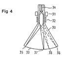
- An additional embodiment of the picture reproduction device involves the use of a single cathode-ray tube as a picture producing means.
- a signal processing device and an electron-beam generator in the cathode-ray tube are arranged to alternately show the first and second pictures, respectively, in such a manner that an observer due to the persistence of vision registers the pictures simultaneously.
- the picture reproduction device comprises electronic means arranged to combine signals produced by the first and second camera means into at least one combined signal for producing a combined picture on the display field.
- the picture reproduction device can also be so designed that the first and second pictures are reproduced on a display field in the form of a visual picture plane, in which they are separately observable by both eyes of an observer in such a manner that the pictures seem to the observer to coincide due to integration in the observer's brain.
- FIG 1 is a vision system shown comprising a picture capture device 1 and a picture reproduction device 2 that are connected to an electric cable 3.
- the picture capture device is directed towards an object field 4, which may be e.g. a section of terrain or the like.
- a first camera means 5 comprises a first optical means 6, which is not shown in detail, and a first detection means 7 consisting of a focal plane with a large number of discrete photo-electric semi-conductor elements arranged in two dimensions.
- the first camera means 5 is mounted so as to be direction controlled via servo-means, not shown, in elevation and azimuth.
- the servo means are remotely controlled, in this case from the site of the picture reproduction device 2.
- Said first optical means 6 has an optic angle such that the object field 4 can be observed with the viewing angle of the first camera means 5, i.e. said first viewing angle.
- a second camera means 8 comprises a second optical means 9, which is not shown in detail, and a second detection means 10, which is similar to the detection means 7.
- the focal length in the optical means 9 is in that case about 10 x the focal length in the first optical means 6, whereby the viewing angle of the second camera means, i.e. the second viewing angle, will be smaller, to a corresponding degree, than the first viewing angle, and the second camera means can only observe a part section 11 of the object field 4.
- the second camera means 8 is mounted so as to be directably controlled in elevation and azimuth by means of servo means, not shown, in a support 12, attached to the first camera means 5. Also the last mentioned servo means are remotely controlled from the site of the picture reproduction device 2.
- the picture reproduction device in figure 2 is assumed to be connected to the picture capture device of the kind shown in figure 1. It comprises a cathode-ray tube 21 with a focusing coil 22 and deflection coils 23, and a screen 24. That cathode-ray tube displays the picture from a first camera means.
- a smaller cathode-ray tube 25 is similarly arranged to display the picture from a second camera means, that last-mentioned picture thus constituting a part of the picture from the first camera means.
- the smaller cathode-ray tube 25 is arranged with its axis of symmetry 26 at right angles to the axis of symmetry 27 of the cathode-ray tube 21.
- An opaque plane mirror 28 is arranged at an angle of 45 o to the axis of symmetry 26 of the smaller cathode-ray tube and is mechanically fixed relative to it.
- the mirror 28 has an extension such that it reflects only the picture from the cathode-ray tube 25.
- the picture producing means the mirror 28 is fixed with its centre on the axis of symmetry 27 of the cathode-ray tube 21. In that case therefore, the picture producing means always displays a picture of an object field with a smaller, central picture section that has a better sharpness in details than the rest of the picture.
- the smaller cathode-ray tube 21 and the mirror 28, the latter being fixed at an angle of 45 o to the axis of symmetry 26 of the former, are jointly movably controlled in a manner such that the plane of the mirror 28 always forms an angle of 45 o to the axis of symmetry 27 of the cathode-ray tube 21, and such that the mirror 28 can be positioned optionally within the area of the screen 24.
- the mechanical arrangements of the controlling of the mirror 28 with the cathode-ray tube 25 are not shown, but some kind of controlling with thin metal wires in two coordinates is conceivable. The controlling is in that case co-ordinated with the movements of the second camera means in the picture capture device.
- the picture reproduction device in figure 3 comprises the same cathode-ray tube 21 and a smaller cathode-ray tube 25 shown in figure 2.
- a semi-opaque mirror 29 which is set at an angle of 45 o to the axis of symmetry 27 of the cathode-ray tube 21, covering the whole screen 24 when observed from the front, i.e. in the direction of the axis of symmetry 27.
- the cathode-ray tube 25 is directed with its axis of symmetry 26 at right angles to the axis of symmetry 27 and is thus directed at an angle of 45 o to the mirror 29.
- the cathode-ray tube 25 is, with fixed orientation relative to the mirror 29, controllably movable witin the reflection range of the mirror 29, co-ordinated with the corresponding movement of a second camera means that receives the picture shown by the cathode ray tube 25.
- An observer observing the picture reproduction device in the direction of the axis of symmetry 27 will therefore see that picture which is reproduced on the screen 24 through the semi-opaque mirror 29, however relatively unclearly, whereas the smaller picture from the cathode-ray tube 25 will be seen with full sharpness and with the richness in detail which is the consequence of the optic construction of the second camera means.
- a not shown signal processing means is arranged to process the incoming signals from the first and second camera means, respectively, so that the part of the picture that is shown by the second camera means excludes the corresponding part of the picture of the first camera means. That is effected in a manner in itself known.
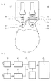
- FIG 5 is shown diagrammatically an embodiment of the vision system according to the invention, where the first and second pictures are integrated electronically.
- a first camera means 39 in the form of a video camera with e.g. the line frequency 15,625 Hz, 50 semi-pictures (frames)/s, connected to a line memory 41 from which a video signal is emitted with 6 repetitively repeated lines with the frequency 93,750 Hz.
- a second camera means 40 also in the form of a video camera, also with the line frequency 15,625 Hz, 50 frames/s, is connected to a frame memory 42.
- the line memory 41 and the frame memory 42 are connected to a video gate 43, which is controlled by a gate program generator 44.
- a video signal is emitted from the video gate 43 to a video motor 45, with a line frequency of 93,750 Hz, 50 frames/s.
- the different units now co-act so that during the repetitive line scanning the second picture replaces the first one in the position where it is located.
- a vision system of that kind requires a monitor with good resolution qualities so that the resolution ability of the eye can be used. In black-and-white such a vision system is feasible.
- Integration of the first and second pictures in an observer's brain can be effected in a vision system according to figure 6.
- the camera means are not shown, but they are of the same type as those used in e.g. the vision system in figure 1.
- a first picture producing means in the form of a cathode-ray tube 46 reproduces the first picture in a visual picture plane 48 with the aid of optical means 53.
- the ray-path is only diagrammatically represented.
- An observer can with one eye 50 via an ocular means 49 register that first picture with an extension of e.g. 6a.
- a second picture producing means also in the form of a cathode-ray tube 47 reproduces the second picture in the same visual picture plane 48 with the aid of optical means 54.
- the observer registers that second picture with the other eye 52 via an ocular means 51. Since the two pictures are being observed separately, each by an eye, they can be integrated into one picture in the observer's brain, in the same manner as when using ordinary binocular field-glasses.
- a vision system of that kind is comparatively cheap, but naturally places certain demands on the observer's eyes. They must function well.
Landscapes
- Engineering & Computer Science (AREA)
- Multimedia (AREA)
- Signal Processing (AREA)
- Testing, Inspecting, Measuring Of Stereoscopic Televisions And Televisions (AREA)
- Closed-Circuit Television Systems (AREA)
Claims (14)
- Videosystem, umfassend eine Bilderfassungsanordnung (1) mit wenigstens einer ersten Kameraeinrichtung (5) und einer zweiten Kameraeinrichtung (8), wobei jede der Kameraeinrichtungen eine Optikeinrichtung (6, 9) und eine elektrooptische Erkennungseinrichtung (7, 10) sowie eine Bildwiedergabeanordnung (2) zur simultanen Wiedergabe von Bildern der Kameraeinrichtung auf wenigstens einem Anzeigefeld (15) umfaßt, wobei die erste Kameraeinrichtung (5) zur Erfassung eines ersten Bildes mit einem großen ersten Sichtwinkel eines Objektfeldes (4) dient und die zweite Kameraeinrichtung (8) zur Erfassung eines zweiten Bildes mit einem kleineren zweiten Sichtwinkel (11) innerhalb des ersten Sichtwinkels des Objektfeldes (4), so daß die zweite Kameraeinrichtung (8) lediglich einen Teilbereich (11) des Objektfeldes (4) beobachtet, dadurch gekennzeichnet, daß die Bildwiedergabeanordnung (2) zur Wiedergabe des ersten Bildes dient, wobei das zweite Bild bis zu einem wahlweisen Grad den Teil des ersten Bildes ersetzt, der dem zweiten Sichtwinkel entspricht, und wobei der erste und der zweite Sichtwinkel dieselbe positionelle Beziehung zum Objektfeld aufweisen wie in den Bildern, die durch die Bildwiedergabeanordnung (2) wiedergegeben werden, und daß die Beziehung Objektfeldausdehnung /Wiedergabeausdahnung dieselbe für das erste und das zweite Bild ist.
- Videosystem nach Anspruch 1, dadurch gekennzeichnet, daß die Bildwiedergabeanordnung (2) grundsätzlich zum vollständigen Ersatz das Teils des ersten Bildes dient, der dem zweiten Sichtwinkel entspricht.
- Videosystem nach Anspruch 1, dadurch gekennzeichnet, daß die erste Kameraeinrichtung (5) richtungssteuerbar ist.
- Videosystem nach Anspruch 3, dadurch gekennzeichnet, daß die zweite Kameraeinrichtung (8) zur ersten Kameraeinrichtung (5) feststehand ausgebildet ist, vorzugsweise mit im wesentlichen im Zentrum des ersten Sichtwinkels angeordnetem zweiten Sichtwinkel.
- Videosystem nach Anspruch 3, dadurch gekennzeichnet, daß die zweite Kameraeinrichtung (8) relativ zur ersten Kameraeinrichtung (5) richtungsstauerbar ist.
- Videosystem nach einem der Ansprüche 3 bis 5, dadurch gekennzeichnet, daß die erste Kameraeinrichtung (5) und/oder die zweite Kameraeinrichtung (8) mittels einer Servoeinrichtung richtungssteuerbar sind bzw. ist.
- Videosystem nach einem der Ansprüche 1 bis 6, dadurch gekennzeichnet, daß die Bildwiedergabeanordnung (2) eine erste Bilderzeugungseinrichtung (21) zur Wiedergabe des ersten Bildes einer ersten Kameraeinrichtung (5) und eine zweite Bilderzeugungseinrichtung (25) zur Wiedergabe des zweiten Bildes von einer zweiten Kameraeirichtung (8) sowie weiterhin einen Spiegel (28, 29) umfaßt, der vor der ersten Bilderzeugungseinrichtung (21) angeordnet ist und das zweite Bild von der zweiten Bilderzeugungseinrichtung (25) reflektiert.
- Videosystem nach Anspruch 7, dadurch gekennzeichnet, daß der Spiegel (28) lichtundurchlässig ist.
- Videosystem nach Anspruch 8, dadurch gekennzeichnet, daß der Spiegel (28) relativ zur zweiten Bilderzeugungseinrichtung (25) festgesetzt ist, wobei sowohl der Spiegel als auch die Bilderzeugungseinrichtung miteinander zur Bewegung relativ zur ersten Bilderzeugungseinrichtung (21) in Übereinstimmung mit den Bewegungen der zweiten Kameraeinrichtung (8) gesteuert werden.
- Videosystem nach Anspruch 7, dadurch gekennzeichnet, daß der Spiegel (29) halblichtdurchlässig ist.
- Videosystem nach Anspruch 10, dadurch gekennzeichnet, daß die zweite Bilderzeugungseinrichtung (25) mit fester Ausrichtung ihrer Symmetrieachse (26) relativ zum Spiegel (29) innerhalb des Reflektionsbereichs des Spiegels (29) beweglich gesteuert wird.
- Videosystem nach einen der Ansprüche 1 bis 5, dadurch gekennzeichnet, daß die Bildwiedergabeanordnung (2) eine Kathodenstrahlröhre (30) zur abwechselnden Darstellung von Bildern von einer ersten und einer zweiten Kameraeinrichtung (5, 8) mit einer wechselnden Frequenz umfaßt, so daß ein Beobachter in Abhängigkeit von der Nachleuchtdauer des Bildes beide Bilder gleichzeitig wahrnimmt.
- Videosystem nach einem der Ansprüche 1 bis 6, dadurch gekennzeichnet, daß die Bildwiedergabeanordnung (2) Elektronikeinrichtungen (31, 42, 43, 44) zur Kombination der Signale, die von der ersten und zweiten Kameraeinrichtung (39, 40) ausgesendet werden, in wenigstens ein kombiniertes Signal zur Erzeugung eines kombinierten Bildes auf dem Anzeigefeld (45) umfaßt.
- Videosystem nach einem der Ansprüche 1 bis 6, dadurch gekennzeichnet, daß die Bildwiedergabeanordnung eine erste Bilderzeugungseinrichtung (46) zur Wiedergabe des ersten Bildes von einer ersten Kameraeinrichtung (5) und eine zweite Bilderzeugungseinrichtung (47) zur Wiedergabe des zweiten Bildes von einer zweiten Kameraeinrichtung (8) umfaßt, wobei das Anzeigefeld durch eine visuelle Bildebene (48) gebildet werden, in der das wiedergegebene erste Bild gesondert durch eine erste Okulareinrichtung (49) mit einem Auge das Beobachters und das wiedergegebene zweite Bild gesondert durch eine zweite Okulareinrichtung (51) mit dem anderen Auge des Beobachters derart beobachtbar ist, daß das ersts und zweite Bild dem Beobachter aufgrund der Integration im Gehirn des Beobachters koinzident erscheint.
Applications Claiming Priority (2)
| Application Number | Priority Date | Filing Date | Title |
|---|---|---|---|
| SE8703315A SE455663B (sv) | 1987-08-27 | 1987-08-27 | Bildsystem, innefattande en bildupptagningsanordning samt en bildatergivningsanordning |
| SE8703315 | 1987-08-27 |
Publications (2)
| Publication Number | Publication Date |
|---|---|
| EP0380507A1 EP0380507A1 (de) | 1990-08-08 |
| EP0380507B1 true EP0380507B1 (de) | 1994-01-05 |
Family
ID=20369392
Family Applications (1)
| Application Number | Title | Priority Date | Filing Date |
|---|---|---|---|
| EP19880907431 Expired - Lifetime EP0380507B1 (de) | 1987-08-27 | 1988-08-26 | Videosystem mit einer bilderfassungsanordnung und einer bildwiedergabeanordnung |
Country Status (5)
| Country | Link |
|---|---|
| EP (1) | EP0380507B1 (de) |
| DE (1) | DE3886948T2 (de) |
| FI (1) | FI94305C (de) |
| SE (1) | SE455663B (de) |
| WO (1) | WO1989002203A1 (de) |
Families Citing this family (3)
| Publication number | Priority date | Publication date | Assignee | Title |
|---|---|---|---|---|
| US7071971B2 (en) | 1997-08-25 | 2006-07-04 | Elbex Video Ltd. | Apparatus for identifying the scene location viewed via remotely operated television camera |
| RU2161871C2 (ru) * | 1998-03-20 | 2001-01-10 | Латыпов Нурахмед Нурисламович | Способ и система для создания видеопрограмм |
| RU2157054C2 (ru) | 1998-09-04 | 2000-09-27 | Латыпов Нурахмед Нурисламович | Способ создания видеопрограмм (варианты) и система для осуществления способа |
Family Cites Families (3)
| Publication number | Priority date | Publication date | Assignee | Title |
|---|---|---|---|---|
| AT358636B (de) * | 1975-05-02 | 1980-02-15 | Eumig | Anordnung mit einer photographischen oder kinematographischen kamera und einer fernseh- kamera |
| DE3146552C2 (de) * | 1981-11-24 | 1983-11-17 | IBP Pietzsch GmbH, 7505 Ettlingen | Verfahren zur Beobachtung mit mehreren Aufnahmesystemen und Einrichtung zur Durchführung des Verfahrens |
| JPS59105776A (ja) * | 1982-12-09 | 1984-06-19 | Sharp Corp | 電子ビユ−フアインダ装置 |
-
1987
- 1987-08-27 SE SE8703315A patent/SE455663B/sv not_active IP Right Cessation
-
1988
- 1988-08-26 WO PCT/SE1988/000437 patent/WO1989002203A1/en not_active Ceased
- 1988-08-26 DE DE88907431T patent/DE3886948T2/de not_active Expired - Fee Related
- 1988-08-26 EP EP19880907431 patent/EP0380507B1/de not_active Expired - Lifetime
-
1990
- 1990-02-26 FI FI900957A patent/FI94305C/fi not_active IP Right Cessation
Also Published As
| Publication number | Publication date |
|---|---|
| SE455663B (sv) | 1988-07-25 |
| SE8703315D0 (sv) | 1987-08-27 |
| FI94305B (fi) | 1995-04-28 |
| FI900957A0 (fi) | 1990-02-26 |
| DE3886948T2 (de) | 1994-04-28 |
| WO1989002203A1 (en) | 1989-03-09 |
| FI94305C (fi) | 1995-08-10 |
| DE3886948D1 (de) | 1994-02-17 |
| EP0380507A1 (de) | 1990-08-08 |
Similar Documents
| Publication | Publication Date | Title |
|---|---|---|
| US5091719A (en) | Helmet display | |
| FI113987B (fi) | Näyttöjärjestely | |
| JP4147188B2 (ja) | 観測者追跡を備えた自動立体ディスプレイ | |
| US3818125A (en) | Stereo television microscope | |
| DE69411185T2 (de) | Stereoskopische bildformungs- und betrachtungsvorrichtung | |
| US5546120A (en) | Autostereoscopic display system using shutter and back-to-back lenticular screen | |
| US20030063186A1 (en) | 2D/3D convertible display | |
| JPS63107294A (ja) | 立体的視覚映写装置 | |
| US5416509A (en) | Method and apparatus for the generation of a stereoscopic presentation | |
| US3932699A (en) | Three-dimensional television | |
| EP0440675B1 (de) | Fernsehvorführungssystem | |
| KR100220888B1 (ko) | 이동 개구를 이용한 다시야 3차원 영상 구현 방법 및 시스템 | |
| US5107117A (en) | Optoelectronic viewing system | |
| US5220429A (en) | Vision system for detecting a picture and reproducing said picture as a picture within a picture | |
| JP3014919B2 (ja) | 3次元情報再生装置 | |
| US4837633A (en) | Electronic boundary framing device and method | |
| JPH1184306A (ja) | 映像観察装置 | |
| WO1989002203A1 (en) | A vision system with a picture capture device and a picture reproduction device | |
| US6195069B1 (en) | Method and apparatus for 3-dimensional motion picture display | |
| US6903708B1 (en) | Viewing instrument | |
| CA2140681C (en) | Wide area coverage infrared search system | |
| RU2090979C1 (ru) | Устройство для воспроизведения объемного изображения | |
| JPH05191838A (ja) | 三次元情報記録再生装置 | |
| US5285307A (en) | Visual field expanding system | |
| JP2864561B2 (ja) | 走査型撮像装置 |
Legal Events
| Date | Code | Title | Description |
|---|---|---|---|
| PUAI | Public reference made under article 153(3) epc to a published international application that has entered the european phase |
Free format text: ORIGINAL CODE: 0009012 |
|
| 17P | Request for examination filed |
Effective date: 19900112 |
|
| AK | Designated contracting states |
Kind code of ref document: A1 Designated state(s): BE CH DE FR GB IT LI NL SE |
|
| 17Q | First examination report despatched |
Effective date: 19920522 |
|
| GRAA | (expected) grant |
Free format text: ORIGINAL CODE: 0009210 |
|
| AK | Designated contracting states |
Kind code of ref document: B1 Designated state(s): BE CH DE FR GB IT LI NL SE |
|
| PG25 | Lapsed in a contracting state [announced via postgrant information from national office to epo] |
Ref country code: SE Effective date: 19940105 |
|
| REF | Corresponds to: |
Ref document number: 3886948 Country of ref document: DE Date of ref document: 19940217 |
|
| ET | Fr: translation filed | ||
| ITF | It: translation for a ep patent filed | ||
| PLBE | No opposition filed within time limit |
Free format text: ORIGINAL CODE: 0009261 |
|
| STAA | Information on the status of an ep patent application or granted ep patent |
Free format text: STATUS: NO OPPOSITION FILED WITHIN TIME LIMIT |
|
| 26N | No opposition filed | ||
| REG | Reference to a national code |
Ref country code: GB Ref legal event code: IF02 |
|
| PGFP | Annual fee paid to national office [announced via postgrant information from national office to epo] |
Ref country code: NL Payment date: 20050803 Year of fee payment: 18 |
|
| PGFP | Annual fee paid to national office [announced via postgrant information from national office to epo] |
Ref country code: FR Payment date: 20050809 Year of fee payment: 18 |
|
| PGFP | Annual fee paid to national office [announced via postgrant information from national office to epo] |
Ref country code: DE Payment date: 20050818 Year of fee payment: 18 |
|
| PGFP | Annual fee paid to national office [announced via postgrant information from national office to epo] |
Ref country code: GB Payment date: 20050824 Year of fee payment: 18 |
|
| PGFP | Annual fee paid to national office [announced via postgrant information from national office to epo] |
Ref country code: CH Payment date: 20050830 Year of fee payment: 18 |
|
| PGFP | Annual fee paid to national office [announced via postgrant information from national office to epo] |
Ref country code: BE Payment date: 20051013 Year of fee payment: 18 |
|
| PG25 | Lapsed in a contracting state [announced via postgrant information from national office to epo] |
Ref country code: LI Free format text: LAPSE BECAUSE OF NON-PAYMENT OF DUE FEES Effective date: 20060831 Ref country code: BE Free format text: LAPSE BECAUSE OF NON-PAYMENT OF DUE FEES Effective date: 20060831 Ref country code: CH Free format text: LAPSE BECAUSE OF NON-PAYMENT OF DUE FEES Effective date: 20060831 |
|
| PGFP | Annual fee paid to national office [announced via postgrant information from national office to epo] |
Ref country code: IT Payment date: 20060831 Year of fee payment: 19 |
|
| PG25 | Lapsed in a contracting state [announced via postgrant information from national office to epo] |
Ref country code: NL Free format text: LAPSE BECAUSE OF NON-PAYMENT OF DUE FEES Effective date: 20070301 Ref country code: DE Free format text: LAPSE BECAUSE OF NON-PAYMENT OF DUE FEES Effective date: 20070301 |
|
| REG | Reference to a national code |
Ref country code: CH Ref legal event code: PL |
|
| GBPC | Gb: european patent ceased through non-payment of renewal fee |
Effective date: 20060826 |
|
| NLV4 | Nl: lapsed or anulled due to non-payment of the annual fee |
Effective date: 20070301 |
|
| REG | Reference to a national code |
Ref country code: FR Ref legal event code: ST Effective date: 20070430 |
|
| PG25 | Lapsed in a contracting state [announced via postgrant information from national office to epo] |
Ref country code: GB Free format text: LAPSE BECAUSE OF NON-PAYMENT OF DUE FEES Effective date: 20060826 |
|
| BERE | Be: lapsed |
Owner name: *SAAB INSTRUMENTS A.B. Effective date: 20060831 |
|
| PG25 | Lapsed in a contracting state [announced via postgrant information from national office to epo] |
Ref country code: FR Free format text: LAPSE BECAUSE OF NON-PAYMENT OF DUE FEES Effective date: 20060831 |
|
| PG25 | Lapsed in a contracting state [announced via postgrant information from national office to epo] |
Ref country code: IT Free format text: LAPSE BECAUSE OF NON-PAYMENT OF DUE FEES Effective date: 20070826 |