EP0380655B1 - Distributeur automatique - Google Patents
Distributeur automatique Download PDFInfo
- Publication number
- EP0380655B1 EP0380655B1 EP89910008A EP89910008A EP0380655B1 EP 0380655 B1 EP0380655 B1 EP 0380655B1 EP 89910008 A EP89910008 A EP 89910008A EP 89910008 A EP89910008 A EP 89910008A EP 0380655 B1 EP0380655 B1 EP 0380655B1
- Authority
- EP
- European Patent Office
- Prior art keywords
- vending machine
- ratchet
- compartment
- support
- support means
- Prior art date
- Legal status (The legal status is an assumption and is not a legal conclusion. Google has not performed a legal analysis and makes no representation as to the accuracy of the status listed.)
- Expired - Lifetime
Links
- 230000004044 response Effects 0.000 claims abstract description 4
- 230000001939 inductive effect Effects 0.000 claims description 5
- 238000001514 detection method Methods 0.000 claims description 3
- 230000007246 mechanism Effects 0.000 abstract description 27
- 238000005192 partition Methods 0.000 description 6
- 230000003466 anti-cipated effect Effects 0.000 description 4
- 238000000034 method Methods 0.000 description 4
- 230000002441 reversible effect Effects 0.000 description 3
- 230000009471 action Effects 0.000 description 2
- 239000011324 bead Substances 0.000 description 2
- 230000000694 effects Effects 0.000 description 2
- 230000005484 gravity Effects 0.000 description 2
- 238000012986 modification Methods 0.000 description 2
- 230000004048 modification Effects 0.000 description 2
- WYTGDNHDOZPMIW-RCBQFDQVSA-N alstonine Natural products C1=CC2=C3C=CC=CC3=NC2=C2N1C[C@H]1[C@H](C)OC=C(C(=O)OC)[C@H]1C2 WYTGDNHDOZPMIW-RCBQFDQVSA-N 0.000 description 1
- 150000001875 compounds Chemical class 0.000 description 1
- 230000001143 conditioned effect Effects 0.000 description 1
- 230000003247 decreasing effect Effects 0.000 description 1
- 238000010586 diagram Methods 0.000 description 1
- 238000012423 maintenance Methods 0.000 description 1
- 230000008520 organization Effects 0.000 description 1
- 230000003534 oscillatory effect Effects 0.000 description 1
- 125000006850 spacer group Chemical group 0.000 description 1
- 238000003466 welding Methods 0.000 description 1
Images
Classifications
-
- G—PHYSICS
- G07—CHECKING-DEVICES
- G07F—COIN-FREED OR LIKE APPARATUS
- G07F11/00—Coin-freed apparatus for dispensing, or the like, discrete articles
- G07F11/02—Coin-freed apparatus for dispensing, or the like, discrete articles from non-movable magazines
- G07F11/04—Coin-freed apparatus for dispensing, or the like, discrete articles from non-movable magazines in which magazines the articles are stored one vertically above the other
- G07F11/16—Delivery means
- G07F11/24—Rotary or oscillatory members
-
- G—PHYSICS
- G07—CHECKING-DEVICES
- G07F—COIN-FREED OR LIKE APPARATUS
- G07F11/00—Coin-freed apparatus for dispensing, or the like, discrete articles
- G07F11/02—Coin-freed apparatus for dispensing, or the like, discrete articles from non-movable magazines
- G07F11/04—Coin-freed apparatus for dispensing, or the like, discrete articles from non-movable magazines in which magazines the articles are stored one vertically above the other
- G07F11/10—Coin-freed apparatus for dispensing, or the like, discrete articles from non-movable magazines in which magazines the articles are stored one vertically above the other two or more magazines having a common delivery chute
Definitions
- This invention relates generally to vending machines and particularly to an improved vending machine for dispensing cylindrical product containers such as bottles or cans in response to customer selections.
- a problem with many conventional machines is that they utilize a considerable number of switches and associated wiring as well as complicated delivery mechanisms. For example, multiple selection machines frequently rely on multiple solenoid operated delivery mechanisms. Not only do such switches and mechanisms consume valuable space but they render the machine susceptible to high maintenance costs.
- vending machines suffer from a lack of versatility in successfully allocating storage space for the anticipated product consumption for each selection. In some vending machines the problem is solved by simply providing additional columns to anticipated prime selections. Recent innovations have resulted in the use of diverting techniques which can result in some product being maintained in the machine for unreasonable lengths of time as well as increasing costs and decreasing reliability. While the application of anticipated use prediction techniques is desirable, the development of dispensing systems capable of utilizing these techniques has not been available.
- US-A-3110417 discloses a vending machine in which a vertical compartment is divided into portions by vertical partitions. The portions are emptied in sequence, which can lead to the problem of old stock remaining in the machine if a compartment is refilled before the last portion has been emptied.
- a dispensing wheel supports an article at the compartment outlet and is controlled by a pawl and ratchet mechanism.
- US-A-3055544 discloses a multilevel gravity feed machine. Inclined platforms each have a number of chutes formed on them and articles are released one from each chute in turn. Escapement cradles at the ends of the chutes are operated in sequence by release arms carried on a rotating bar which is controlled by a ratchet wheel.
- US-A-2735580 discloses a vending machine in which vertical compartments each have a sliding ejection mechanism.
- the ejection mechanism for a compartment is selected by rotation of a rod to engage the particular mechanism, and the rod is then pushed to operate the ejection mechanism.
- the present invention provides a vending machine comprising article storage means including a plurality of storage compartments disposed in side-by-side relation, each compartment being adapted to receive a plurality of adjacent articles, a respective support means disposed at the end of each compartment and operatively supporting an article in a first position and tending to move to a second position under the weight of the article, a plurality of release means each controlling movement of a respective support means between the first and second position incident to releasing an article, actuating means to actuate a selected one of said release means and permit rotation of the associated support means, and control means for said actuating means, characterised in that: each storage compartment includes generally aligned first and second portions each portion being adapted to receive a plurality of adjacent articles, each support means supports an article in each compartment portion of the respective compartment by support elements which cooperate with a retainer to support an article in each compartment portion, said retainer comprising for one compartment portion an escrow means which provides a hold position for said articles to allow alternate delivery of said articles from said compartment portions on
- This vending machine provides a particularly efficient product storage capability by reducing the space requirements for switching and delivery mechanisms. In this machine switching is virtually eliminated and the delivery mechanism is simplified by reducing the requirement for multiple electromagnetic devices such as motors and solenoids to a minimum by utilizing common drive mechanisms.
- the vending machine allows for selection between the storage compartments, and releases in turn an article from each portion of a compartment to ensure that old stock is vended first from the compartment when it is refilled.
- said actuating means comprises an elongate member extending between the release means and having indexing means positionable adjacent a selected one of the release means for actuation of the selected release means.
- the elongate member is a drive shaft.
- the indexing means is subject to rotary and longitudinal movement and the control means includes a position detection means operative to monitor automatically rotary and longitudinal movement of the indexing means.
- each support means has a star configuration substantially smaller than the dispensed article.
- the ratchet means is attached to and rotates with the support means and the pawl means includes spaced means engageable with said ratchet means, one of said spaced means being movable out of engagement with said ratchet means and the other of said spaced means being simultaneously movable into incipient engagement with said ratchet means to determine the amount of rotation of said ratchet means in response to reciprocation of the elongate member.
- the elongate member is a drive shaft having a plurality of angularly related indexing members attached thereto, each indexing member being engageable with an associated release means, electrical means rotate said drive shaft so that a selected indexing member is disposed adjacent a selected release means, electrical means induces alternating motion into said drive shaft and indexing members so that a said indexing member engages and actuates a respective release means to permit movement of a respective support means.
- the storage compartments are substantially vertical columns.
- each ratchet means is fixedly attached to one end of an associated support means and rotatable with said support means, and each pawl means is pivotally mounted adjacent the respective ratchet means and movable into and out of engagement with said ratchet means to permit rotation of said support means.
- the means for rotating said drive shaft is a first electric motor
- the means for inducing alternating motion into said drive shaft is a second electric motor including eccentric drive means and linkage means between said eccentric drive means and said drive shaft.
- the means for rotating said drive shaft is an electric motor, and the means for inducing alternating motion into said drive shaft is a solenoid.
- the pawl means includes an end portion and means pivotally attaching said end portion to the other portion for one-way movement of said end portion relative to said other portion, and said actuating means includes means for oscillating said drive shaft and selected indexing member to induce said alternating motion into said indexing number.
- a second plurality of said compartments is provided, a compartment of said second plurality being aligned with a respective compartment of said first plurality of compartments and each rotatable support means includes independent portions having axially adjacent ends, each independent portion supporting articles in the respective compartment of said first and second plurality of compartments, and said release means includes a ratchet means at adjacent ends of each support means and rotatable with its associated support means and an associated pawl means, and said actuating means drive shaft indexing members are disposed between said pawl means, to selectively actuate each of said ratchet means.
- each ratchet means is integrally formed with its associated support means.
- each support means has a three-pointed star configuration.
- each support means is disposed within the associated compartment.
- each support means is formed from a bar having a substantially uniform cross-section with a three-pointed star configuration.
- the ratchet means is a ratchet wheel integrally formed with said bar and having a plurality of ratchet teeth at equally spaced intervals, and the pawl means is an escapement member having spaced lug members sequentially engageable with said teeth.
- each compartment includes a lower end and a member disposed at said lower end to narrow the exit and direct said articles onto said associated support means.
- each compartment portion is adapted to receive a plurality of adjacent, generally cylindrical articles.
- each support means has a three-pointed star configuration and each ratchet means includes six teeth.
- This vending machine is provided with a dispensing mechanism which is ideally suited to utilize sophisticated anticipated use predicting techniques which reduce restocking and maintain product freshness and helps prevent depletion of popular selections.
- the product storage capability can be additionally enhanced by independent front and rear storage of the vertical columns.
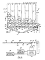
- the vending machine 10 includes a frame 12 divided, in the embodiment shown, into eight storage compartments 1-8 by end walls 14 and 18 and intermediate partition walls 16.
- the compartments are substantially vertical.
- the columns 1-8 are of sufficient depth to provide forward portions 1a, 2a, 3a, etc. and rearward portions 1b, 2b, 3b, etc. so that each column can accommodate two cylindrical articles or containers C such as cans or bottles, end to end.
- Each of the columns 1-8 is of sufficient width to accommodate staggered vertical rows of said containers C.
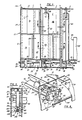
- the frame 12 also includes front and rear plates 20 and 22, connecting the partition walls 16; a front guard plate 24 spaced from said front plate 20, as by spacers 26, and side plates 28 and 30 which interconnect the rear plate 22 and the front guard plate 24. Plates 20 and 24 cooperate to provide a housing for the container release mechanism which is generally indicated by numeral 32 and will be described later.
- each of said plates 16 includes a transverse member 36, attached as by welding.
- the transverse members 36 effectively narrow the column and define the exit path of the containers C therein, said members 36 including an upper ramp portion 38, a vertical portion 40 and a lower inclined portion 42.
- a retainer plate 50 which includes an upper portion 52, extending between and connected to front and rear plates 20 and 22 and, in the front portion of the column only, a curved escrow portion 54.
- the containers are passed through the column exit by means of a three-point turnstile member 60 disposed below each column, which is axially supported in rotatable relation between the rear plate 22 and the guard plate 24 and cooperates with the retainer 50 to provide a turnstile system.
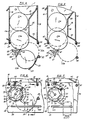
- the turnstile member 60 which is generally star-shaped in configuration, includes three points 61, 63 and 65 separated by concave surfaces 66 compatibly configurated to support a container C.
- the turnstile members 60 are mounted between the rear and guard plates 22 and 24 by stub shafts 68 and 69, respectively, in freely rotatable relation.
- the turnstile members provide support means for the containers and the axis of rotation of said members is disposed within the column and offset from weight center of the supported container. The result of this is that the turnstile members tend to rotate under the weight of the containers.
- the three-point turnstile 60 extends through the front and rear columns, eg column portions 2a and 2b and each turnstile supports two containers C.
- the upper portion 52 of the retainer 50 also extends through the front and rear columns but the lower, escrow portion extends only through the front column portion 2a.
- Corresponding containers C1a and C1b, C2a and C2b in the front and rear column portions are axially aligned.
- the containers C1a and C1b, C2a and C2b and C3a are shown in full line representation in a first position, and in phantom outline representation in a second position.
- One hundred and twenty degrees (120°) of movement of the turnstile member 60 are required to release a container C.
- the turnstile projection 65 holds containers C2a and C2b in the front and rear portions of column 2 in the position shown in full line representation.
- the turnstile projection 61 cooperates with the escrow portion 54 to hold container C3a in the position shown in full line representation.
- container C3a When the turnstile member 60 is allowed to rotate sixty degrees (60°) to the position shown in phantom outline container C3a is delivered and containers C2a and C2b both move to the position shown in phantom outline in which they are supported by turnstile projection 65 and retainer member 52.
- container C2a When the turnstile member 60 is allowed to rotate a further sixty degrees (60°) container C2a will move into the position formerly occupied by container C3a and be held by the turnstile member 60 and cooperating escrow portion 54 in the front column portion.
- Container C2b however will be delivered since no escrow portion is provided in the rear column portion.
- containers C are delivered alternately from each column portion for each sixty degrees (60°) of rotation of the turnstile member 60 but one hundred and twenty degrees (120°) of movement are necessary to deliver a container from the same column.
- the release mechanism which controls the rotation of the turnstile member 60 from a first position, in which they are supported by the turnstile member to a second position incident to being dispensed will now be described with particular reference to FIGS. 6-8.
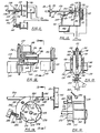
- each turnstile member 60 extends through the front plate 20 and is provided at its front end with a coaxially integrally mounted and integrally formed ratchet wheel 70 which rotates with the turnstile member 60.
- the ratchet wheel 70 includes a plurality of radially extending teeth 71-76, six (6) in number in the embodiment shown, and a circular back plate 77.
- An escapement member or pawl 80 is pivotally mounted adjacent the ratchet wheel 70 by a pivot shaft 81 extending between the front wall 20 and the guard wall 24.
- the escapement member 80 is generally arcuate and includes lugs 82 and 84 which are engageable respectively with the ratchet wheel teeth 74 and 76 in the position shown.
- the escapement member 80 includes a socket 86 providing a seat for the lower end of a spring 88 and said spring is engageable at its upper end with an abutment member 90 with the result that the lug 82 is biased into engagement with the uppermost tooth 74.
- the escapement member 80 includes an outstanding member 92, constituting a first engagement means which is engageable by a reciprocable member such as indexing pin 102 mounted to an elongate drive shaft 100, and constituting a second engagement means.
- a reciprocable member such as indexing pin 102 mounted to an elongate drive shaft 100
- a second engagement means constituting a second engagement means.
- the drive shaft 100 is mounted between sidewalls 28 and 30.
- the shaft 100 includes a plurality of longitudinally spaced, radially outstanding pins 101 through 108 disposed in angular relation to each other about the shaft axis and constituting engagement means. As shown eight (8) pins are provided at equal angles of forty-five degrees (45°) and each pin, such as pin 102, is selectively engageable with an associated adjacent escapement member 80.
- the shaft 100 is rotatable and shiftable so that the selected pin corresponding to a customer selection of a product in column 2, can be rotated into an upright position aligned with the escapement projecting member 92. The shaft 100 can then be shifted, as shown by reference to FIGS.
- a total movement of one hundred and twenty degrees (120°) is necessary to release a container C so that the front and rear containers in a column are released consecutively as the turnstile 60 and ratchet wheel 70 are rotated at sixty degree (60°) intervals.
- FIGS. 10 and 11 are directed respectively to alternative arrangements for providing this movement.
- the shaft 100 is carried by a bearing 96, mounted to wall 28, through which it can slide. At the other end the bearing 98 is connected to an auxiliary shaft 110 parallel to the motor shaft 112 and driven from said motor by a drive chain assembly 114.
- the drive shaft 100 is connected to the auxiliary shaft 110 by means of a shaft coupler 117.
- the shaft coupler 117 includes a longitudinal slot 118 which receives a pin 120 fixedly attached to the auxiliary shaft 110.
- the drive shaft 100 is shifted axially by means of a motor M2 which includes a motor shaft 123 having an eccentric arm 124 rotatable with said shaft 123 and connected to the coupler sleeve 117 by means of a pivoted link 126.
- a motor M2 which includes a motor shaft 123 having an eccentric arm 124 rotatable with said shaft 123 and connected to the coupler sleeve 117 by means of a pivoted link 126.
- rotation of the arm 124 through three hundred and sixty degrees (360°) results in fore and aft movement of the drive shaft 100 equal to twice the radius of the arm 124.
- Rotation of the drive shaft 100 to its proper angular position so that a selected pin, e.g. pin 102, is conditioned to engage an escapement member 80 (FIG. 6) to initiate delivery of a container C, is achieved by a control means such as shown in FIG. 2.
- the angular and axial position of the drive shaft 100 is provided by a Shaft Position Detector 130 to which information is fed by means of cooperating encoder elements 132 and 134 (FIG. 10).
- This encoding means can be provided by photo-optic, magnetic or other well known position detection means.
- the indication of the desired product to be vended is provided by the Product Selector 140.
- the motors M1 and M2 (which can be AC, DC or stepper type motors) are actuated in accordance with information input to a Motor Control 142 by the product Selector 140 and the Shaft Position Detector 130.
- the shaft 100 is connected to the shaft 150 of a motor M mounted to the wall 30 by means of a shaft coupler 152.
- the shaft coupler 152 includes a disc flange 154 and the coupler includes a slot 156 which receives a pin 158 fixedly attached to the motor shaft 150.
- the drive shaft 100 is shifted axially by means of a positioning lever 161, which is pivotally mounted to the housing by pivot shaft 162 intermediate its ends. At its upper end 164 the lever is bifurcated to receive the flange 154 and at its lower end 166 the shaft is pivoted to the core of a solenoid S.
- the electronic control system utilizes a microprocessor but can also be implemented using logic gate circuitry.
- turnstile members 160 are provided on each side of a partition wall 122, which are independently rotatable on a common shaft 168.
- a six-tooth ratchet wheel 170 is provided at the end of each turnstile member 160 and individual escapement members 180 are pivotally mounted to partition wall 122 by a common pivot shaft 181.
- the turnstile members 160 and ratchet wheels 170 are substantially identical with those discussed above.
- the escapement members 180 are substantially identical except for the inwardly turned lower portions carrying the projecting member 192. This arrangement permits the use of a single rod 100 having appropriate pins 101-108, in lieu of two independent rods.
- the control system is modified in order to provide for double usage.
- FIGS. 14 and 15 A modified release mechanism is shown in FIGS. 14 and 15 which utilizes a reversible drive motor and requires no shifting mechanism.
- the ratchet wheel 270 and the turnstile member 260 are substantially identical to those described above.
- the escapement member 280 is different in that it includes a pivoted finger 292 which is upwardly movable relative to the other portion of the escapement member 280 but is precluded from moving downwardly relative to said other portion by virtue of a pivot stop 293.
- the drive shaft 200 is driven by a reversible motor M3 and like the previous embodiment includes a plurality of pins 201-208 which however are longer. When the shaft is rotated clockwise all pins lift their associated pivot fingers 292.
- a selected pin e.g.
- pin 202 is disposed in close adjacency to its associated pivot finger 292 and counterclockwise motion of the shaft 200 rotates pin 202 downwardly which pushes the finger 292 downwardly together with the escapement member 280 which pivots and the result of this is that the engagement lug 282 pivots out of engagement with ratchet tooth 272 so that the turnstile member 260 rotates under the weight of a container C until lug 284 engages with ratchet tooth 273.
- Clockwise motion induced into the shaft 200 causes the end of the escapement member 280 carrying the pivot finger 292 to move upwardly under the action of spring 288 so that lug 284 moves out of engagement with ratchet tooth 273 and lug 282 moves into engagement with ratchet tooth 272.
- the oscillating movement of the pin 202 causes a total rotation of the ratchet wheel 270, and the turnstile member 260 of one hundred and twenty degrees (120°).
- the operation is similar to that described above. It will be understood that the length of the pins 201-208 and the angular oscillatory motion are chosen so that the only one pin engages its associated pivot finger at any one time.
- sending machine used herein is intended to include both cash and credit merchandising machines.
Landscapes
- Physics & Mathematics (AREA)
- General Physics & Mathematics (AREA)
- Vending Machines For Individual Products (AREA)
- Control Of Vending Devices And Auxiliary Devices For Vending Devices (AREA)
- Soil Working Implements (AREA)
- Eye Examination Apparatus (AREA)
- Formation And Processing Of Food Products (AREA)
- De-Stacking Of Articles (AREA)
Abstract
Claims (21)
- Distributeur automatique (10) comprenant un moyen de stockage des articles, englobant plusieurs compartiments de stockage (1-8), agencés côte à côte, chaque compartiment (1-8) pouvant recevoir plusieurs articles adjacents (C), un moyen de support respectif (60), agencé à l'extrémité de chaque compartiment, supportant en service un article (C) dans une première position, et tendant à se déplacer vers une deuxième position sous l'effet du poids de l'article (C), plusieurs moyens de libération (32), commandant chacun le déplacement d'un moyen de support respectif (60) entre les première et deuxième positions pour entraîner la libération d'un article (C), un moyen d'actionnement (100) pour actionner un desdits moyens de libération sélectionné (32) et permettre la rotation du moyen de support associé (60), et un moyen de commande (130; 132; 134; 140; 142; M1; M2) dudit moyen d'actionnement (100).
caractérisé en ce que:
chaque compartiment de stockage (1-8) englobe des première et deuxième parties généralement alignées (1a-8a; 1b-8b), chaque partie (1a-8a; 1b-8b) étant destinée à recevoir plusieurs articles adjacents (C), chaque moyen de support (60) supportant un article (C) dans chaque partie de compartiment du compartiment respectif par l'intermédiaire d'éléments de support (61; 63; 65), coopérant avec un élément de retenue (50) pour supporter un article dans chaque partie de compartiment (1a-8a; 1b-8b), ledit moyen de retenue comprenant pour une partie de compartiment (1a-8a) un moyen de dépôt (54) établissant une position de retenue desdits articles (C) pour permettre une décharge alternée desdits articles (C) desdites parties de compartiment (1a-8a: 1b-8b) lors de la rotation dudit moyen de support (60), chaque moyen de libération (32) englobant un moyen de rochet (70) comportant plusieurs dents (71-76), et un moyen de cliquet (80), le nombre desdites dents (71-76) étant au moins le double de celui des éléments de support (61; 63; 65) sur le moyen de support (60), ledit moyen de libération commandant ainsi la rotation dudit moyen de support pour décharger lesdits articles (C) dans ladite première partie de compartiment (1a-8a) en alternance avec lesdits articles (C) dans ladite deuxième partie de compartiment (1b-8b). - Distributeur automatique selon la revendication 1, caractérisé en ce que ledit moyen d'actionnement (100) comprend un élément allongé (100) s'étendant entre le moyen de libération (32) et comportant un moyen d'indexage (101-108) pouvant être positionné près d'un moyen de libération sélectionné (32) pour actionner le moyen de libération sélectionné (32).
- Distributeur automatique selon la revendication 2, caractérisé en ce que l'élément allongé est un arbre de commande (100).
- Distributeur automatique selon les revendications 1, 2 ou 3, caractérisé en ce que le moyen d'indexage (101-108) subit un déplacement rotatif et longitudinal, le moyen de commande englobant un moyen de détection de la position (130) servant à contrôler automatiquement le déplacement rotatif et longitudinal du moyen d'indexage (101-108).
- Distributeur automatique selon les revendications 1, 2, 3 ou 4, caractérisé en ce que chaque moyen de support (60) a une configuration en étoile (61; 63; 65) sensiblement plus petite que l'article distribué (C).
- Distributeur automatique selon la revendication 1, caractérisé en ce que le moyen de rochet (70) est fixé au moyen de support (60) et tourne avec celui-ci, le moyen de cliquet (80) englobant des moyens espacés (82; 84) pouvant s'engager dans ledit moyen de rochet (70), l'un desdits moyens espacés (82) pouvant être dégagé dudit moyen de rochet (70), et l'autre desdits moyens espacés (84) pouvant être simultanément déplacé pour commencer à s'engager dans ledit moyen de rochet (70), pour déterminer le degré de rotation dudit moyen de rochet (70) en réponse au mouvement de va-et-vient de l'élément allongé (100).
- Distributeur automatique selon la revendication 1, caractérisé en ce que l'élément allongé (100) est un arbre de commande (100) comportant plusieurs éléments d'indexage à relation angulaire (101-108) qui y sont fixés. chaque élément d'indexage (101-108) pouvant s'engager dans un moyen de libération associé (32), un moyen électrique (M1) servant à faire tourner ledit arbre de commande (100), de sorte qu'un élément d'indexage sélectionné (101-108) est agencé près d'un moyen de libération sélectionné (32), un moyen électrique (M2) servant à entraîner un déplacement alternatif dudit élément de commande (100) et des éléments d'indexage (101-108), de sorte qu'un dit élément d'indexage (101-108) s'engage dans un moyen de libération respectif (32) et l'actionne pour permettre le déplacement d'un moyen de support respectif (60).
- Distributeur automatique selon la revendication 1, caractérisé en ce que les compartiments de stockage (1-8) sont des colonnes pratiquement verticales.
- Distributeur automatique selon la revendication 1, caractérisé en ce que chaque moyen de rochet (70) est fixé fermement à une extrémité d'un moyen de support associé (60) et en ce qu'il peut tourner avec ledit moyen de support (60), chaque moyen de cliquet (80) étant monté par pivotement près du moyen de rochet respectif (70) et pouvant s'engager dans ledit moyen de rochet (70) et s'en dégager, pour permettre la rotation dudit moyen de support (60).
- Distributeur automatique selon la revendication 7, caractérisé en ce que le moyen (M1) destiné à faire tourner ledit arbre de commande (100) est un premier moteur électrique (M1), le moyen (M2) pour entraîner un déplacement alternatif dudit moyen d'entraînement étant un deuxième moteur électrique (M2), englobant un moyen d'entraînement excentrique (124) et un moyen de liaison (126) entre ledit moyen d'entraînement excentrique (124) et ledit arbre de commande (100).
- Distributeur automatique selon la revendication 7, caractérisé en ce que le moyen (M) destiné à faire tourner ledit arbre de commande (100) est un moteur électrique (M), le moyen (S) destiné à entraîner un déplacement alternatif dudit arbre de commande (100) étant un solénoïde (S).
- Distributeur automatique selon la revendication 9, caractérisé en ce que le moyen de cliquet (280) englobe une partie d'extrémité (292) et un moyen (293) fixant par pivotement ladite partie d'extrémité (292) à l'autre partie (280) en vue d'un déplacement unidirectionnel de ladite partie d'extrémité (292) par rapport à ladite autre partie (280), ledit moyen d'actionnement (200) englobant un moyen pour faire osciller ledit arbre de commande (200) et un élément d'indexage sélectionné (201-208) pour entraîner ledit déplacement alternatif dudit élément d'indexage (201-208).
- Distributeur automatique selon la revendication 7, caractérisé en ce qu'il comprend plusieurs deuxièmes desdits compartiments (1-8), un compartiment desdits plusieurs deuxièmes compartiments étant aligné avec un compartiment respectif desdits plusieurs premiers compartiments, chaque moyen de support rotatif (160) englobant des parties indépendantes (160), comportant des extrémités axialement adjacentes, chaque partie indépendante (160) supportant des articles (C) dans le compartiment respectif desdits plusieurs premiers et deuxièmes compartiments (1-8), ledit moyen de libération (32) englobant un moyen de rochet (170) au niveau des extrémités adjacentes de chaque moyen de support (160) et pouvant tourner avec son moyen de support associé (160), ainsi qu'un moyen de cliquet associé (180), lesdits éléments d'indexage (101-108) dudit arbre de commande constituant le moyen d'actionnement étant agencés entre ledit moyen de cliquet (180), pour actionner sélectivement l'un desdits moyens de rochet (170).
- Distributeur automatique selon la revendication 9, caractérisé en ce que chaque moyen de rochet (70) fait partie intégrante de son moyen de support associé (60).
- Distributeur automatique selon la revendication 1, caractérisé en ce que chaque moyen de support (60) a une configuration en étoile à trois pointes.
- Distributeur automatique selon la revendication 1, caractérisé en ce que l'axe de rotation de chaque moyen de support (60) est agencé dans le compartiment associé (1-8).
- Distributeur automatique selon la revendication 9, caractérisé en ce que chaque moyen de support (60) est produit à partir d'une barre (60), ayant une section pratiquement uniforme avec une configuration en étoile à trois pointes (61; 63; 65).
- Distributeur automatique selon la revendication 17, caractérisé en ce que le moyen de rochet (70) est une roue à rochet (70) faisant partie intégrante de ladite barre (60) et comportant plusieurs dents de rochet (71-76) à des intervalles espacés de façon égale, le moyen de cliquet (80) étant un élément d'espacement (80) comportant des éléments de languette espacés (82; 84) pouvant s'engager de façon séquentielle dans lesdites dents (71-76).
- Distributeur automatique selon la revendication 1, caractérisé en ce que chaque compartiment (1-8) englobe une extrémité inférieure et un élément (36) agencé au niveau de ladite extrémité inférieure pour rétrécir la sortie et diriger lesdits articles (C) sur ledit moyen de support associé (60).
- Distributeur automatique selon la revendication 9, caractérisé en ce que chaque partie de compartiment (1a-8a; 1b-8b) est destinée à recevoir plusieurs articles adjacents, généralement cylindriques (C).
- Distributeur automatique selon la revendication 20, caractérisé en ce que chaque moyen de support (60) a une configuration en étoile à trois pointes (61; 63; 65), chaque moyen de rochet (70) englobant six dents (71-76).
Applications Claiming Priority (5)
| Application Number | Priority Date | Filing Date | Title |
|---|---|---|---|
| US23096388A | 1988-08-10 | 1988-08-10 | |
| US230963 | 1988-08-10 | ||
| US07/230,843 US4991740A (en) | 1988-08-10 | 1988-08-10 | Vending machine |
| PCT/US1989/003442 WO1990001754A1 (fr) | 1988-08-10 | 1989-08-09 | Distributeur automatique |
| US230843 | 2002-08-28 |
Publications (3)
| Publication Number | Publication Date |
|---|---|
| EP0380655A1 EP0380655A1 (fr) | 1990-08-08 |
| EP0380655A4 EP0380655A4 (en) | 1990-12-12 |
| EP0380655B1 true EP0380655B1 (fr) | 1996-10-23 |
Family
ID=26924615
Family Applications (2)
| Application Number | Title | Priority Date | Filing Date |
|---|---|---|---|
| EP89909480A Expired - Lifetime EP0407481B1 (fr) | 1988-08-10 | 1989-08-09 | Distributeur automatique |
| EP89910008A Expired - Lifetime EP0380655B1 (fr) | 1988-08-10 | 1989-08-09 | Distributeur automatique |
Family Applications Before (1)
| Application Number | Title | Priority Date | Filing Date |
|---|---|---|---|
| EP89909480A Expired - Lifetime EP0407481B1 (fr) | 1988-08-10 | 1989-08-09 | Distributeur automatique |
Country Status (7)
| Country | Link |
|---|---|
| EP (2) | EP0407481B1 (fr) |
| JP (2) | JP2791909B2 (fr) |
| KR (2) | KR0157219B1 (fr) |
| AU (2) | AU628375B2 (fr) |
| CA (2) | CA1335373C (fr) |
| DE (2) | DE68927374T2 (fr) |
| WO (2) | WO1990001755A1 (fr) |
Families Citing this family (6)
| Publication number | Priority date | Publication date | Assignee | Title |
|---|---|---|---|---|
| KR0157219B1 (ko) * | 1988-08-10 | 1999-02-18 | 엘. 레바수어 죠셉 | 자동 판매기 |
| FR2672714A1 (fr) * | 1991-02-13 | 1992-08-14 | Planex Sa | Distributeur automatique d'articles conditionnes. |
| BE1008382A3 (nl) * | 1994-05-17 | 1996-04-02 | Mes Philippe Gomarus Marie | Verdeelinrichting voor voorwerpen. |
| JP2001525283A (ja) | 1997-12-09 | 2001-12-11 | ザ・グッドイヤー・タイヤ・アンド・ラバー・カンパニー | タイヤの圧力センサ、およびそれに関する方法 |
| CZ2005550A3 (cs) * | 2005-09-01 | 2006-11-15 | Sielaff Bohemia S. R. O. | Automat pro výdej kusových predmetu |
| JP6444415B2 (ja) * | 2013-12-23 | 2018-12-26 | ザ コカ・コーラ カンパニーThe Coca‐Cola Company | 製品供給シュート機構を有する商品販売機 |
Family Cites Families (13)
| Publication number | Priority date | Publication date | Assignee | Title |
|---|---|---|---|---|
| US2735580A (en) * | 1956-02-21 | Galinetal | ||
| US3104779A (en) * | 1963-09-24 | denzer | ||
| US2864532A (en) * | 1953-06-04 | 1958-12-16 | Rowe Mfg Co Inc | Packet merchandising machine |
| US2901964A (en) * | 1957-02-04 | 1959-09-01 | Lloyd F Brogan | Vending machine |
| US3055544A (en) * | 1958-10-20 | 1962-09-25 | Rowe Mfg Company Inc | Multilevel gravity-feed packagemerchandising machine |
| US3110417A (en) * | 1959-02-17 | 1963-11-12 | Wilmer J Wingate | Automatic can vending machine |
| US3057513A (en) * | 1959-05-04 | 1962-10-09 | Odis A Turman | Package dispensing machine |
| DE1217671B (de) * | 1960-04-25 | 1966-05-26 | Alfred Neff Dr | Vorrichtung zur zyklischen Ausgabe von Getraenkeflaschen aus Selbstverkaeufern |
| US3467275A (en) * | 1967-12-26 | 1969-09-16 | Vaughan Ind Inc | Container dispenser having an escapement assembly |
| US3819087A (en) * | 1972-10-10 | 1974-06-25 | Umc Ind | Article-dispensing apparatus |
| US3904076A (en) * | 1974-08-15 | 1975-09-09 | Cavalier Corp | Adaptable dispensing apparatus with unique escrow bar and associated latch mechanism |
| FR2502477B2 (fr) * | 1981-03-30 | 1985-09-13 | Guigan Jean | Dispositif pour le stockage et la distribution automatique d'objets |
| KR0157219B1 (ko) * | 1988-08-10 | 1999-02-18 | 엘. 레바수어 죠셉 | 자동 판매기 |
-
1989
- 1989-08-09 KR KR1019900700742A patent/KR0157219B1/ko not_active Expired - Fee Related
- 1989-08-09 AU AU40644/89A patent/AU628375B2/en not_active Ceased
- 1989-08-09 WO PCT/US1989/003443 patent/WO1990001755A1/fr not_active Ceased
- 1989-08-09 EP EP89909480A patent/EP0407481B1/fr not_active Expired - Lifetime
- 1989-08-09 DE DE68927374T patent/DE68927374T2/de not_active Expired - Fee Related
- 1989-08-09 KR KR1019900700743A patent/KR0157218B1/ko not_active Expired - Fee Related
- 1989-08-09 WO PCT/US1989/003442 patent/WO1990001754A1/fr not_active Ceased
- 1989-08-09 DE DE68924645T patent/DE68924645T2/de not_active Expired - Fee Related
- 1989-08-09 JP JP1509336A patent/JP2791909B2/ja not_active Expired - Fee Related
- 1989-08-09 JP JP1508837A patent/JP2791908B2/ja not_active Expired - Fee Related
- 1989-08-09 EP EP89910008A patent/EP0380655B1/fr not_active Expired - Lifetime
- 1989-08-09 AU AU42036/89A patent/AU628387B2/en not_active Ceased
- 1989-08-10 CA CA000608032A patent/CA1335373C/fr not_active Expired - Fee Related
- 1989-08-10 CA CA000608031A patent/CA1335195C/fr not_active Expired - Fee Related
Also Published As
| Publication number | Publication date |
|---|---|
| AU628387B2 (en) | 1992-09-17 |
| KR900702485A (ko) | 1990-12-07 |
| EP0407481A4 (en) | 1993-01-07 |
| WO1990001754A1 (fr) | 1990-02-22 |
| EP0407481A1 (fr) | 1991-01-16 |
| KR900702484A (ko) | 1990-12-07 |
| EP0380655A4 (en) | 1990-12-12 |
| DE68924645T2 (de) | 1996-04-18 |
| JPH03501902A (ja) | 1991-04-25 |
| WO1990001755A1 (fr) | 1990-02-22 |
| EP0407481B1 (fr) | 1995-10-25 |
| JP2791908B2 (ja) | 1998-08-27 |
| AU4064489A (en) | 1990-03-05 |
| JP2791909B2 (ja) | 1998-08-27 |
| JPH03502017A (ja) | 1991-05-09 |
| KR0157219B1 (ko) | 1999-02-18 |
| EP0380655A1 (fr) | 1990-08-08 |
| KR0157218B1 (ko) | 1999-02-18 |
| AU628375B2 (en) | 1992-09-17 |
| CA1335373C (fr) | 1995-04-25 |
| AU4203689A (en) | 1990-03-05 |
| DE68927374T2 (de) | 1997-03-27 |
| DE68924645D1 (de) | 1995-11-30 |
| DE68927374D1 (de) | 1996-11-28 |
| CA1335195C (fr) | 1995-04-11 |
Similar Documents
| Publication | Publication Date | Title |
|---|---|---|
| US4991740A (en) | Vending machine | |
| US4991739A (en) | Vending machine | |
| US3795345A (en) | Product dispensing apparatus | |
| US3498497A (en) | Double-depth serpentine can vender | |
| US3055544A (en) | Multilevel gravity-feed packagemerchandising machine | |
| US3991907A (en) | Solid merchandise dispensing system for mechanical or electrical control | |
| US2923392A (en) | Horizontal conveyor sandwich merchandising machine | |
| US20010030197A1 (en) | Apparatus and method for article dispensing | |
| KR19990045287A (ko) | 대형 상품 자동판매 시스템 | |
| EP0178244B1 (fr) | Dispositif vendeur d'articles | |
| US3362582A (en) | Vending machine with separately acting, series, article releasers | |
| US3146907A (en) | Dispensing device | |
| US3231129A (en) | Staggered stack vending machine | |
| CA1335373C (fr) | Machine distributrice | |
| WO1999041716A1 (fr) | Moyen de distribution pour distributeur automatique | |
| US3158246A (en) | Vending machine | |
| US3224631A (en) | Dispensing mechanism for articles in front to back staggered stacks | |
| US3325049A (en) | Selective slant shelf vender having a product delivery conveyor | |
| US4625893A (en) | Stamp booklet dispenser mechanism | |
| US4354614A (en) | Can and bottle vending | |
| US3158290A (en) | Retarder for dispensing mechanism for articles in a stack | |
| US3151772A (en) | Dispensing mechanism for articles in staggered stack | |
| US3292816A (en) | Reversible regulator for dispensing mechanism for articles in staggered stacks | |
| JPH0757146A (ja) | 自動販売機の商品収納搬出装置 | |
| US3295716A (en) | Reversible motor driven regulator for dispensing mechanism for articles in staggered stacks |
Legal Events
| Date | Code | Title | Description |
|---|---|---|---|
| PUAI | Public reference made under article 153(3) epc to a published international application that has entered the european phase |
Free format text: ORIGINAL CODE: 0009012 |
|
| 17P | Request for examination filed |
Effective date: 19900411 |
|
| AK | Designated contracting states |
Kind code of ref document: A1 Designated state(s): DE FR GB IT |
|
| A4 | Supplementary search report drawn up and despatched |
Effective date: 19901023 |
|
| AK | Designated contracting states |
Kind code of ref document: A4 Designated state(s): DE FR GB IT |
|
| 17Q | First examination report despatched |
Effective date: 19920731 |
|
| GRAH | Despatch of communication of intention to grant a patent |
Free format text: ORIGINAL CODE: EPIDOS IGRA |
|
| GRAH | Despatch of communication of intention to grant a patent |
Free format text: ORIGINAL CODE: EPIDOS IGRA |
|
| GRAH | Despatch of communication of intention to grant a patent |
Free format text: ORIGINAL CODE: EPIDOS IGRA |
|
| GRAA | (expected) grant |
Free format text: ORIGINAL CODE: 0009210 |
|
| AK | Designated contracting states |
Kind code of ref document: B1 Designated state(s): DE FR GB IT |
|
| PG25 | Lapsed in a contracting state [announced via postgrant information from national office to epo] |
Ref country code: IT Free format text: LAPSE BECAUSE OF FAILURE TO SUBMIT A TRANSLATION OF THE DESCRIPTION OR TO PAY THE FEE WITHIN THE PRE;WARNING: LAPSES OF ITALIAN PATENTS WITH EFFECTIVE DATE BEFORE 2007 MAY HAVE OCCURRED AT ANY TIME BEFORE 2007. THE CORRECT EFFECTIVE DATE MAY BE DIFFERENT FROM THE ONE RECORDED.SCRIBED TIME-LIMIT Effective date: 19961023 |
|
| REF | Corresponds to: |
Ref document number: 68927374 Country of ref document: DE Date of ref document: 19961128 |
|
| ET | Fr: translation filed | ||
| PLBE | No opposition filed within time limit |
Free format text: ORIGINAL CODE: 0009261 |
|
| STAA | Information on the status of an ep patent application or granted ep patent |
Free format text: STATUS: NO OPPOSITION FILED WITHIN TIME LIMIT |
|
| 26N | No opposition filed | ||
| PGFP | Annual fee paid to national office [announced via postgrant information from national office to epo] |
Ref country code: GB Payment date: 19990804 Year of fee payment: 11 |
|
| PGFP | Annual fee paid to national office [announced via postgrant information from national office to epo] |
Ref country code: DE Payment date: 19990809 Year of fee payment: 11 |
|
| PGFP | Annual fee paid to national office [announced via postgrant information from national office to epo] |
Ref country code: FR Payment date: 19990810 Year of fee payment: 11 |
|
| PG25 | Lapsed in a contracting state [announced via postgrant information from national office to epo] |
Ref country code: GB Free format text: LAPSE BECAUSE OF NON-PAYMENT OF DUE FEES Effective date: 20000809 |
|
| GBPC | Gb: european patent ceased through non-payment of renewal fee |
Effective date: 20000809 |
|
| PG25 | Lapsed in a contracting state [announced via postgrant information from national office to epo] |
Ref country code: FR Free format text: LAPSE BECAUSE OF NON-PAYMENT OF DUE FEES Effective date: 20010430 |
|
| PG25 | Lapsed in a contracting state [announced via postgrant information from national office to epo] |
Ref country code: DE Free format text: LAPSE BECAUSE OF NON-PAYMENT OF DUE FEES Effective date: 20010501 |
|
| REG | Reference to a national code |
Ref country code: FR Ref legal event code: ST |