EP0380657B1 - Missile launcher - Google Patents
Missile launcher Download PDFInfo
- Publication number
- EP0380657B1 EP0380657B1 EP89910756A EP89910756A EP0380657B1 EP 0380657 B1 EP0380657 B1 EP 0380657B1 EP 89910756 A EP89910756 A EP 89910756A EP 89910756 A EP89910756 A EP 89910756A EP 0380657 B1 EP0380657 B1 EP 0380657B1
- Authority
- EP
- European Patent Office
- Prior art keywords
- bag
- missile
- gas
- tube
- generator
- Prior art date
- Legal status (The legal status is an assumption and is not a legal conclusion. Google has not performed a legal analysis and makes no representation as to the accuracy of the status listed.)
- Expired - Lifetime
Links
- 239000004677 Nylon Substances 0.000 claims description 5
- VYPSYNLAJGMNEJ-UHFFFAOYSA-N Silicium dioxide Chemical compound O=[Si]=O VYPSYNLAJGMNEJ-UHFFFAOYSA-N 0.000 claims description 5
- 229920001778 nylon Polymers 0.000 claims description 5
- 239000004744 fabric Substances 0.000 claims description 4
- 238000004891 communication Methods 0.000 claims description 2
- 235000012239 silicon dioxide Nutrition 0.000 claims description 2
- 239000000377 silicon dioxide Substances 0.000 claims description 2
- 239000011358 absorbing material Substances 0.000 claims 2
- 239000011810 insulating material Substances 0.000 claims 2
- 239000007789 gas Substances 0.000 description 23
- 239000000463 material Substances 0.000 description 8
- 239000003380 propellant Substances 0.000 description 7
- 239000004449 solid propellant Substances 0.000 description 5
- 238000000034 method Methods 0.000 description 4
- 230000000007 visual effect Effects 0.000 description 4
- 239000002826 coolant Substances 0.000 description 3
- PXIPVTKHYLBLMZ-UHFFFAOYSA-N Sodium azide Chemical compound [Na+].[N-]=[N+]=[N-] PXIPVTKHYLBLMZ-UHFFFAOYSA-N 0.000 description 2
- 238000001816 cooling Methods 0.000 description 2
- 238000001514 detection method Methods 0.000 description 2
- 230000000694 effects Effects 0.000 description 2
- 238000012423 maintenance Methods 0.000 description 2
- 230000002787 reinforcement Effects 0.000 description 2
- 238000003466 welding Methods 0.000 description 2
- 239000002759 woven fabric Substances 0.000 description 2
- 229920002943 EPDM rubber Polymers 0.000 description 1
- 239000004593 Epoxy Substances 0.000 description 1
- 230000005540 biological transmission Effects 0.000 description 1
- 238000004140 cleaning Methods 0.000 description 1
- 230000000295 complement effect Effects 0.000 description 1
- 238000007796 conventional method Methods 0.000 description 1
- 230000003467 diminishing effect Effects 0.000 description 1
- 238000010304 firing Methods 0.000 description 1
- 239000012530 fluid Substances 0.000 description 1
- 230000000977 initiatory effect Effects 0.000 description 1
- 238000009413 insulation Methods 0.000 description 1
- 239000007788 liquid Substances 0.000 description 1
- 239000012528 membrane Substances 0.000 description 1
- 229910052751 metal Inorganic materials 0.000 description 1
- 239000002184 metal Substances 0.000 description 1
- 231100000252 nontoxic Toxicity 0.000 description 1
- 230000003000 nontoxic effect Effects 0.000 description 1
- JTJMJGYZQZDUJJ-UHFFFAOYSA-N phencyclidine Chemical compound C1CCCCN1C1(C=2C=CC=CC=2)CCCCC1 JTJMJGYZQZDUJJ-UHFFFAOYSA-N 0.000 description 1
- 239000004033 plastic Substances 0.000 description 1
- 230000000284 resting effect Effects 0.000 description 1
- 230000000452 restraining effect Effects 0.000 description 1
- 239000002760 rocket fuel Substances 0.000 description 1
- 238000007789 sealing Methods 0.000 description 1
- 238000012546 transfer Methods 0.000 description 1
Images

Classifications
-
- F—MECHANICAL ENGINEERING; LIGHTING; HEATING; WEAPONS; BLASTING
- F42—AMMUNITION; BLASTING
- F42B—EXPLOSIVE CHARGES, e.g. FOR BLASTING, FIREWORKS, AMMUNITION
- F42B29/00—Noiseless, smokeless, or flashless missiles launched by their own explosive propellant
Definitions
- the present invention relates generally to a tube launched missile, and, more particularly, to a launcher for such a missile which substantially reduces both the launch visual signature and the acoustic signature while providing the capability of delivering a higher launch velocity than conventionally obtained.
- rocket motor which is an integral part of the missile.
- Such rocket motors must be contained within a limited envelope because of the need for space by other sub-systems, such as controls, a beacon, wire bobbins, and the like, which usually must occupy the same base region of the missile.
- controls such as controls, a beacon, wire bobbins, and the like, which usually must occupy the same base region of the missile.
- wire bobbins such as wire bobbins, and the like
- US-A-4,333,382 describes a hydraulic actuating system utilizing a high pressure piston stroke over a short distance for accelerating a missile up to launch speed immediately prior to initiation of the missile motor.
- this apparatus includes a pneumatic/hydraulic system to systematically and sequentially remove restraining supports holding the missile to the launcher, and a telescopic piston assembly for driving the missile to a predetermined initial velocity.
- FR-A-2534681 relates to missile-launching apparatus comprising an open-ended tube for receiving a missile and having fore and aft ends, a selectively operable pressurized gas generator having external dimensions enabling sliding receipt thereof within the tube's aft end, a first expandable, bag-like member having an opening through which gas may pass from the gas generator in one direction and a second expandable, bag-like member having an opening through which gas may pass from the gas generator in the opposite direction.
- One bag-like member acts to launch the missile whereas the other acts to eject ballast from the breech of the launcher, thereby diminishing recoil effects.
- FR-A-1558093 relates to a pneumatic missile launcher.
- the launcher includes rearwardly facing nozzles through which gas is allowed to escape to act against recoil forces.
- the missile is propelled along the launch tube by a massive carrier against which the pneumatic forces act.
- the carrier is essentially captive in the tube and, on reaching the fore end, gives up its own momentum to the then rearwardly-moving tube. This giving up of momentum compensates for recoil in large measure, the remaining compensation occurring by means of the nozzle over a period of time much longer than the missile launch time.
- This invention provides missile launching apparatus comprising: an open-ended tube for receiving a missile and having fore and aft ends; a selectively actuatable pressurized gas generator having external dimensions enabling sliding receipt thereof within the tube's aft end; and an expandable, air-tight bag-like member having an opening for receiving gas from the gas generator; characterized by: the generator having a diffuser through which gas can move in a first direction into the bag-like member and a plurality of openings through which gas can move in a second direction, generally opposite to the said first direction; the said plurality of openings being in communication with the atmosphere; and the arrangement of diffuser and the said plurality of openings being such that at all times during the launch of the missile the recoil force acting on the generator is substantially zero.
- the launch bag closed end is provided with a configured outer surface complementary to that of the missile base in order to accommodate specially shaped structures on the base.
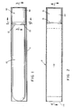
- a missile 10 to be launched from an open-ended tube 11 conventionally has its own launch motor (not shown) which may be a unitary part of the missile. Not only does this arrangement raise questions of efficiency and reduction in payload for the missile, but such launchings are accompanied by relatively high visual and acoustic signatures which desirably should be eliminated or reduced.
- the launcher 12 of this invention includes a bag 13 having a closed end 14 and an opposite open end 15, the closed end being located adjacent to the base of the missile when positioned within the launch tube 11.
- the open end 14 of the bag is sealed to a gas generating inflator/thruster 16, which, upon ignition, provides a supply of pressurized gas to the interior of the bag causing it to rapidly expand and eject the missile.
- the invention launches a missile with a substantial reduction in the visual and acoustic signature which reduces the possibility of detection and the taking of countermeasures against the missile.
- the collapsible bag 13 is an elastic membrane preferably constructed of a closely woven fabric such as nylon forming a substantially non-porous sidewall.
- the expanded bag is a cylindrical envelope having a closed end 14 which can preferably be reinforced if required.
- the closed end is contemplated for contact with the missile aft end in use, so reinforcement may be needed to prevent damage to or leakage of the bag.
- Such reinforcement may take several different forms, a preferred one of which is to use multiple layers of the nylon fabric or other bag material.
- the opposite end 15 of the launch bag is open and is of such a dimension relative to the thruster that it can be received thereon and preferably sealed to the thruster by a quantity of epoxy 17, for example, that extends completely about the thruster.
- a clamp ring (not shown) may be used to effect sealing relation between the bag and the thruster.
- the lower end portion 18 of the bag open end is preferably treated with a material which has good heat insulation properties to protect the bag material from excessive heat transfer during inflation. Suitable materials for this purpose include any polymeric material, such as EPDM, for example.
- EPDM polymeric material
- the interior of the bag forms a substantially gas tight plenum which is inflated by gases upon burning a solid propellant. As seen best in FIG. 2, when the bag 13 is fully inflated it and the thruster 16 substantially fill the missile launch tube.
- the inflator/thruster is seen to include a shell casing 19 which has an outer diameter such that it can be slidingly received within the launch tube 11.
- a diffuser 20 consisting of an arcuately shaped metal plate has a diameter such that it can be fit within the inner end of the thruster shell casing 19 and includes a plurality of openings 21 for transmission of propellant gas, as will be described.
- the diffuser plate is affixed to the inner wall of the housing by any suitable means such as welding or bonding, for example.
- a quantity of granulated coolant material 22 such as silicon dioxide (Si02) may be provided, for example, which would act to remove heat from the propellant gas as it moves therethrough, and, in that way, reduce heat applied to the bag during launch.
- a gas coolant bed would be secured in place against the diffuser plate by a wire mesh containment screen 23 and secured to the casing inner wall surface by welding, or other suitable means.
- a cylindrical wire mesh container 24 has one end secured to the center of screen 23 and extends coaxially rearward.
- a quantity 25 of a suitable solid propellant is located within the container.
- a low signature solid propellant such as sodium azide, for example, which has a relatively low temperature on burning and is non-toxic, is excellent for this purpose.
- the propellant container is enclosed at its rear by a plate 26 including a centrally located igniter 27.
- the propellant containment plate has a plurality of openings 28 which serve as nozzles in generating thrust to equilibrate eject recoil.
- the thruster 16 with collapsed launch bag 13 is located in the lower end of the launch tube 11 and the missile is placed within the tube resting its lower end upon the bag end portion 14 as shown in FIG. 1.
- the igniter 27 is then energized and the solid propellant on ignition produces pressurized gas which passes through the coolant material 22 (if used) and then through the diffuser 20 rapidly expanding the launch bag to its fully inflated condition as shown in FIG. 2.
- the described invention By use of the described invention, there is a substantial reduction in the acoustic signature as well as visual signature which reduces the possibility of detection of the missile launching and countermeasures being taken.
- missile pay-load capability is enhanced, or alternatively, missile flight weight is reduced since the expended launch motor is not carried to the target, Since the launch motor has been removed from the missile, there is additional volume for controls, beacon, wire bobbins, or other missile components.
- the solid propellant gas source could be replaced by a suitable slow burning liquid propellant carried within a suitable container.
- nylon fabric is preferred for constructing the bag 13, a number of flexible or elastic plastic materials or closely woven fabrics would be satisfactory for this purpose.
Landscapes
- Engineering & Computer Science (AREA)
- General Engineering & Computer Science (AREA)
- Aiming, Guidance, Guns With A Light Source, Armor, Camouflage, And Targets (AREA)
- Toys (AREA)
- Air Bags (AREA)
- Feeding, Discharge, Calcimining, Fusing, And Gas-Generation Devices (AREA)
Applications Claiming Priority (2)
| Application Number | Priority Date | Filing Date | Title |
|---|---|---|---|
| US07/229,882 US4944210A (en) | 1988-08-08 | 1988-08-08 | Missile launcher |
| US229882 | 1994-04-19 |
Publications (2)
| Publication Number | Publication Date |
|---|---|
| EP0380657A1 EP0380657A1 (en) | 1990-08-08 |
| EP0380657B1 true EP0380657B1 (en) | 1993-08-25 |
Family
ID=22863042
Family Applications (1)
| Application Number | Title | Priority Date | Filing Date |
|---|---|---|---|
| EP89910756A Expired - Lifetime EP0380657B1 (en) | 1988-08-08 | 1989-06-19 | Missile launcher |
Country Status (9)
| Country | Link |
|---|---|
| US (1) | US4944210A (tr) |
| EP (1) | EP0380657B1 (tr) |
| JP (1) | JPH0646159B2 (tr) |
| CA (1) | CA1316731C (tr) |
| DE (1) | DE68908691T2 (tr) |
| ES (1) | ES2017135A6 (tr) |
| IL (1) | IL90705A (tr) |
| TR (1) | TR25122A (tr) |
| WO (1) | WO1990001668A1 (tr) |
Cited By (2)
| Publication number | Priority date | Publication date | Assignee | Title |
|---|---|---|---|---|
| EP3736523A1 (de) | 2019-05-10 | 2020-11-11 | MBDA Deutschland GmbH | System und vorrichtung zum starten eines flugkörpers |
| US12540043B2 (en) | 2024-06-26 | 2026-02-03 | Eagle Technology, Llc | Ejection of items using an inflatable device with rolling convolutions |
Families Citing this family (22)
| Publication number | Priority date | Publication date | Assignee | Title |
|---|---|---|---|---|
| SE463580B (sv) * | 1989-11-21 | 1990-12-10 | Saab Missiles Ab | Projektil foer spridning av en last med tidsfoerdroejning |
| US5279199A (en) * | 1992-08-14 | 1994-01-18 | Hughes Aircraft Company | Technique and apparatus for rearward launch of a missile |
| US5333528A (en) * | 1992-08-28 | 1994-08-02 | Hughes Aircraft Company | Multiple missile ejection system |
| US6032567A (en) * | 1998-03-16 | 2000-03-07 | The United States Of America As Represented By The Secretary Of The Navy | Surf zone mine clearance |
| US6354182B1 (en) | 2000-04-18 | 2002-03-12 | Philip J. Milanovich | Launch assist system |
| US6418870B1 (en) | 2000-05-31 | 2002-07-16 | Systems Engineering Associates Corporation | Torpedo launch mechanism and method |
| CN1681551B (zh) | 2002-09-06 | 2011-03-02 | 雷斯梅德有限公司 | 呼吸面罩的前额衬垫 |
| NZ608551A (en) | 2004-06-16 | 2014-10-31 | Resmed Ltd | Cushion for a respiratory mask assembly |
| KR100629930B1 (ko) * | 2004-07-30 | 2006-09-29 | 국방과학연구소 | 유도탄 사출 발사 장치 |
| US7908973B2 (en) * | 2004-11-05 | 2011-03-22 | Raytheon Company | Lightweight deployment system and method |
| CN101822862B (zh) | 2005-01-12 | 2013-07-10 | 雷斯梅德有限公司 | 具有角撑板软垫的呼吸面罩 |
| DE202006021250U1 (de) | 2005-01-12 | 2014-02-11 | Resmed Limited | Stirnstützen für Gesichtsmasken |
| NZ578010A (en) * | 2006-06-16 | 2011-05-27 | Resmed Ltd | Forehead support for facial masks extendable and contratable with the use of an adjustment knob |
| US7739938B2 (en) | 2006-09-22 | 2010-06-22 | The United States Of America As Represented By The Secretary Of The Army | Gas generator launcher for small unmanned aerial vehicles (UAVs) |
| EP2107331B1 (en) * | 2008-04-03 | 2013-07-31 | Whitehead Sistemi Subacquei S.p.A. | Torpedo launch device |
| US20090308274A1 (en) * | 2008-06-11 | 2009-12-17 | Lockheed Martin Corporation | Integrated Pusher Plate for a Canister- or Gun-Launched Projectile and System Incorporating Same |
| US8151797B2 (en) * | 2008-10-30 | 2012-04-10 | Hsiner Company, Ltd. | Respiration mask assembly |
| US8439301B1 (en) | 2011-07-18 | 2013-05-14 | Systems Engineering Associates Corporation | Systems and methods for deployment and operation of unmanned aerial vehicles |
| DE102012206709B4 (de) * | 2012-04-24 | 2014-02-13 | Thyssenkrupp Marine Systems Gmbh | Unterseeboot |
| KR102222167B1 (ko) * | 2012-06-07 | 2021-03-03 | 에어로바이론먼트, 인크. | 발사관 내에서 무인 항공기를 탈착가능하게 연결시키는 시스템 |
| CN107718605A (zh) * | 2017-11-16 | 2018-02-23 | 西安方元明科技股份有限公司 | 一种发射箱箱体及其制备方法、发射箱及其制备方法 |
| CN109373813B (zh) * | 2018-10-10 | 2020-09-01 | 中国科学院长春光学精密机械与物理研究所 | 一种发射筒及一种发射装置 |
Family Cites Families (17)
| Publication number | Priority date | Publication date | Assignee | Title |
|---|---|---|---|---|
| US3035494A (en) * | 1960-01-26 | 1962-05-22 | Musser C Walton | Recoil adjusting device |
| NL132545C (tr) * | 1967-03-16 | |||
| DE2055805C3 (de) * | 1970-11-13 | 1974-03-28 | Messerschmitt-Boelkow-Blohm Gmbh, 8000 Muenchen | Abschußvorrichtung für Geschosse |
| US3871684A (en) * | 1971-08-02 | 1975-03-18 | Dow Chemical Co | Gas generator |
| US3944251A (en) * | 1972-04-28 | 1976-03-16 | Specialty Products Development Corporation | Gas generator for automobile driver restraint bag |
| US3827715A (en) * | 1972-04-28 | 1974-08-06 | Specialty Prod Dev Corp | Pyrotechnic gas generator with homogenous separator phase |
| DE2237344C3 (de) * | 1972-07-29 | 1979-02-15 | Messerschmitt-Boelkow-Blohm Gmbh, 8000 Muenchen | Abschußvorrichtung für Geschosse |
| US4068862A (en) * | 1974-11-20 | 1978-01-17 | Nissan Motor Co., Ltd. | Safety bag inflation apparatus with extendible guard member against contact of bag with heated gas generator |
| US4047465A (en) * | 1976-07-23 | 1977-09-13 | The United States Of America As Represented By The Secretary Of The Army | Telescoped explosive driver |
| GB1556859A (en) * | 1976-11-29 | 1979-11-28 | Ici Ltd | Shaped explosive charge device for underwater use |
| JPS581333B2 (ja) * | 1978-03-02 | 1983-01-11 | 日産自動車株式会社 | 燃焼器 |
| US4203347A (en) * | 1978-04-10 | 1980-05-20 | The Boeing Company | Shock suppressing apparatus and method for a rocket launcher |
| FR2470358A1 (fr) * | 1979-11-22 | 1981-05-29 | Serat | Perfectionnements apportes aux armes lancant des projectiles |
| US4392412A (en) * | 1980-10-30 | 1983-07-12 | The United States Of America As Represented By The Secretary Of The Army | Gaseous blast reducer |
| US4426909A (en) * | 1981-10-20 | 1984-01-24 | The Boeing Company | Noise, flash and smoke suppressor apparatus and method for rocket launcher |
| FR2581748B2 (fr) * | 1982-10-19 | 1993-02-19 | Serat | Perfectionnements apportes aux systemes d'armes lanceurs de projectiles |
| FR2534681B1 (fr) * | 1982-10-19 | 1987-08-07 | Serat | Perfectionnements apportes aux systemes d'armes lanceurs de projectiles, notamment aux charges propulsives et a la balistique interieure |
-
1988
- 1988-08-08 US US07/229,882 patent/US4944210A/en not_active Expired - Fee Related
-
1989
- 1989-06-19 WO PCT/US1989/002663 patent/WO1990001668A1/en not_active Ceased
- 1989-06-19 EP EP89910756A patent/EP0380657B1/en not_active Expired - Lifetime
- 1989-06-19 DE DE89910756T patent/DE68908691T2/de not_active Expired - Fee Related
- 1989-06-19 JP JP1510064A patent/JPH0646159B2/ja not_active Expired - Lifetime
- 1989-06-21 IL IL90705A patent/IL90705A/xx not_active IP Right Cessation
- 1989-06-26 CA CA000603941A patent/CA1316731C/en not_active Expired - Fee Related
- 1989-07-24 TR TR89/0935A patent/TR25122A/tr unknown
- 1989-07-27 ES ES8902657A patent/ES2017135A6/es not_active Expired - Fee Related
Cited By (3)
| Publication number | Priority date | Publication date | Assignee | Title |
|---|---|---|---|---|
| EP3736523A1 (de) | 2019-05-10 | 2020-11-11 | MBDA Deutschland GmbH | System und vorrichtung zum starten eines flugkörpers |
| DE102019003322B4 (de) | 2019-05-10 | 2024-11-07 | Mbda Deutschland Gmbh | System und Vorrichtung zum Starten eines Flugkörpers |
| US12540043B2 (en) | 2024-06-26 | 2026-02-03 | Eagle Technology, Llc | Ejection of items using an inflatable device with rolling convolutions |
Also Published As
| Publication number | Publication date |
|---|---|
| DE68908691T2 (de) | 1993-12-09 |
| IL90705A0 (en) | 1990-01-18 |
| DE68908691D1 (de) | 1993-09-30 |
| JPH0646159B2 (ja) | 1994-06-15 |
| CA1316731C (en) | 1993-04-27 |
| US4944210A (en) | 1990-07-31 |
| TR25122A (tr) | 1992-10-01 |
| EP0380657A1 (en) | 1990-08-08 |
| JPH03501878A (ja) | 1991-04-25 |
| IL90705A (en) | 1991-12-12 |
| WO1990001668A1 (en) | 1990-02-22 |
| ES2017135A6 (es) | 1991-01-01 |
Similar Documents
| Publication | Publication Date | Title |
|---|---|---|
| US4944210A (en) | Missile launcher | |
| US3499364A (en) | Apparatus for submerged launching of missiles | |
| US6164179A (en) | Submarine deployable vertical launch spar buoy | |
| US3279319A (en) | Floatable rocket launcher | |
| US9567108B2 (en) | Gas gun launcher | |
| US3252281A (en) | Rocket system and method | |
| US5363791A (en) | Weapons launch system | |
| US11359877B2 (en) | Apparatus and method for accelerating an object via an external free jet | |
| US3166979A (en) | Rocket igniter and damping plate assembly | |
| US3465638A (en) | Hypervelocity gun | |
| US7484450B2 (en) | Apparatus and method for launching a vehicle | |
| US4724738A (en) | Space entry actuator launch system | |
| EP1289828A1 (en) | Improved torpedo launch mechanism and method | |
| US7398721B1 (en) | Cold-gas munitions launch system | |
| US5918307A (en) | Underwater projectile launcher | |
| US3135161A (en) | Expendable-piston tube missile launcher | |
| US6125834A (en) | Free-piston cutting machine | |
| US7243609B1 (en) | Telescoping buoyancy capsule | |
| US3425316A (en) | Exothermic steam generator | |
| RU2245503C1 (ru) | Транспортно-пусковой модуль | |
| RU2025645C1 (ru) | Ракета космического назначения | |
| US20200355465A1 (en) | System and apparatus for launching a missile | |
| JPH05288494A (ja) | 飛しょう体の射出装置 | |
| US3217599A (en) | Missile launching apparatus | |
| US3355985A (en) | Dual propellant launch for solid rockets |
Legal Events
| Date | Code | Title | Description |
|---|---|---|---|
| PUAI | Public reference made under article 153(3) epc to a published international application that has entered the european phase |
Free format text: ORIGINAL CODE: 0009012 |
|
| 17P | Request for examination filed |
Effective date: 19900222 |
|
| AK | Designated contracting states |
Kind code of ref document: A1 Designated state(s): CH DE FR GB IT LI NL SE |
|
| 17Q | First examination report despatched |
Effective date: 19910708 |
|
| GRAA | (expected) grant |
Free format text: ORIGINAL CODE: 0009210 |
|
| AK | Designated contracting states |
Kind code of ref document: B1 Designated state(s): CH DE FR GB IT LI NL SE |
|
| PG25 | Lapsed in a contracting state [announced via postgrant information from national office to epo] |
Ref country code: SE Effective date: 19930825 Ref country code: LI Effective date: 19930825 Ref country code: CH Effective date: 19930825 |
|
| REF | Corresponds to: |
Ref document number: 68908691 Country of ref document: DE Date of ref document: 19930930 |
|
| ET | Fr: translation filed | ||
| ITF | It: translation for a ep patent filed | ||
| REG | Reference to a national code |
Ref country code: CH Ref legal event code: PL |
|
| PLBE | No opposition filed within time limit |
Free format text: ORIGINAL CODE: 0009261 |
|
| STAA | Information on the status of an ep patent application or granted ep patent |
Free format text: STATUS: NO OPPOSITION FILED WITHIN TIME LIMIT |
|
| 26N | No opposition filed | ||
| PGFP | Annual fee paid to national office [announced via postgrant information from national office to epo] |
Ref country code: FR Payment date: 19970510 Year of fee payment: 9 |
|
| PGFP | Annual fee paid to national office [announced via postgrant information from national office to epo] |
Ref country code: GB Payment date: 19970520 Year of fee payment: 9 |
|
| PGFP | Annual fee paid to national office [announced via postgrant information from national office to epo] |
Ref country code: NL Payment date: 19970526 Year of fee payment: 9 |
|
| PG25 | Lapsed in a contracting state [announced via postgrant information from national office to epo] |
Ref country code: GB Free format text: LAPSE BECAUSE OF NON-PAYMENT OF DUE FEES Effective date: 19980619 |
|
| PG25 | Lapsed in a contracting state [announced via postgrant information from national office to epo] |
Ref country code: NL Free format text: LAPSE BECAUSE OF NON-PAYMENT OF DUE FEES Effective date: 19990101 |
|
| GBPC | Gb: european patent ceased through non-payment of renewal fee |
Effective date: 19980619 |
|
| PG25 | Lapsed in a contracting state [announced via postgrant information from national office to epo] |
Ref country code: FR Free format text: LAPSE BECAUSE OF NON-PAYMENT OF DUE FEES Effective date: 19990226 |
|
| NLV4 | Nl: lapsed or anulled due to non-payment of the annual fee |
Effective date: 19990101 |
|
| REG | Reference to a national code |
Ref country code: FR Ref legal event code: ST |
|
| PGFP | Annual fee paid to national office [announced via postgrant information from national office to epo] |
Ref country code: DE Payment date: 20000524 Year of fee payment: 12 |
|
| PG25 | Lapsed in a contracting state [announced via postgrant information from national office to epo] |
Ref country code: DE Free format text: LAPSE BECAUSE OF NON-PAYMENT OF DUE FEES Effective date: 20020403 |
|
| PG25 | Lapsed in a contracting state [announced via postgrant information from national office to epo] |
Ref country code: IT Free format text: LAPSE BECAUSE OF NON-PAYMENT OF DUE FEES;WARNING: LAPSES OF ITALIAN PATENTS WITH EFFECTIVE DATE BEFORE 2007 MAY HAVE OCCURRED AT ANY TIME BEFORE 2007. THE CORRECT EFFECTIVE DATE MAY BE DIFFERENT FROM THE ONE RECORDED. Effective date: 20050619 |