EP0380883B1 - Moteur hors-bord - Google Patents
Moteur hors-bord Download PDFInfo
- Publication number
- EP0380883B1 EP0380883B1 EP89313502A EP89313502A EP0380883B1 EP 0380883 B1 EP0380883 B1 EP 0380883B1 EP 89313502 A EP89313502 A EP 89313502A EP 89313502 A EP89313502 A EP 89313502A EP 0380883 B1 EP0380883 B1 EP 0380883B1
- Authority
- EP
- European Patent Office
- Prior art keywords
- engine
- outboard
- cylinder block
- oil
- oil pan
- Prior art date
- Legal status (The legal status is an assumption and is not a legal conclusion. Google has not performed a legal analysis and makes no representation as to the accuracy of the status listed.)
- Expired - Lifetime
Links
Images


Classifications
-
- F—MECHANICAL ENGINEERING; LIGHTING; HEATING; WEAPONS; BLASTING
- F16—ENGINEERING ELEMENTS AND UNITS; GENERAL MEASURES FOR PRODUCING AND MAINTAINING EFFECTIVE FUNCTIONING OF MACHINES OR INSTALLATIONS; THERMAL INSULATION IN GENERAL
- F16C—SHAFTS; FLEXIBLE SHAFTS; ELEMENTS OR CRANKSHAFT MECHANISMS; ROTARY BODIES OTHER THAN GEARING ELEMENTS; BEARINGS
- F16C9/00—Bearings for crankshafts or connecting-rods; Attachment of connecting-rods
- F16C9/02—Crankshaft bearings
-
- F—MECHANICAL ENGINEERING; LIGHTING; HEATING; WEAPONS; BLASTING
- F02—COMBUSTION ENGINES; HOT-GAS OR COMBUSTION-PRODUCT ENGINE PLANTS
- F02B—INTERNAL-COMBUSTION PISTON ENGINES; COMBUSTION ENGINES IN GENERAL
- F02B29/00—Engines characterised by provision for charging or scavenging not provided for in groups F02B25/00, F02B27/00 or F02B33/00 - F02B39/00; Details thereof
- F02B29/04—Cooling of air intake supply
- F02B29/045—Constructional details of the heat exchangers, e.g. pipes, plates, ribs, insulation, materials, or manufacturing and assembly
- F02B29/0462—Liquid cooled heat exchangers
-
- F—MECHANICAL ENGINEERING; LIGHTING; HEATING; WEAPONS; BLASTING
- F02—COMBUSTION ENGINES; HOT-GAS OR COMBUSTION-PRODUCT ENGINE PLANTS
- F02B—INTERNAL-COMBUSTION PISTON ENGINES; COMBUSTION ENGINES IN GENERAL
- F02B61/00—Adaptations of engines for driving vehicles or for driving propellers; Combinations of engines with gearing
- F02B61/04—Adaptations of engines for driving vehicles or for driving propellers; Combinations of engines with gearing for driving propellers
- F02B61/045—Adaptations of engines for driving vehicles or for driving propellers; Combinations of engines with gearing for driving propellers for marine engines
-
- F—MECHANICAL ENGINEERING; LIGHTING; HEATING; WEAPONS; BLASTING
- F02—COMBUSTION ENGINES; HOT-GAS OR COMBUSTION-PRODUCT ENGINE PLANTS
- F02B—INTERNAL-COMBUSTION PISTON ENGINES; COMBUSTION ENGINES IN GENERAL
- F02B75/00—Other engines
- F02B75/16—Engines characterised by number of cylinders, e.g. single-cylinder engines
- F02B75/18—Multi-cylinder engines
- F02B75/20—Multi-cylinder engines with cylinders all in one line
-
- F—MECHANICAL ENGINEERING; LIGHTING; HEATING; WEAPONS; BLASTING
- F02—COMBUSTION ENGINES; HOT-GAS OR COMBUSTION-PRODUCT ENGINE PLANTS
- F02M—SUPPLYING COMBUSTION ENGINES IN GENERAL WITH COMBUSTIBLE MIXTURES OR CONSTITUENTS THEREOF
- F02M35/00—Combustion-air cleaners, air intakes, intake silencers, or induction systems specially adapted for, or arranged on, internal-combustion engines
- F02M35/10—Air intakes; Induction systems
- F02M35/1015—Air intakes; Induction systems characterised by the engine type
- F02M35/10157—Supercharged engines
- F02M35/10163—Supercharged engines having air intakes specially adapted to selectively deliver naturally aspirated fluid or supercharged fluid
-
- F—MECHANICAL ENGINEERING; LIGHTING; HEATING; WEAPONS; BLASTING
- F02—COMBUSTION ENGINES; HOT-GAS OR COMBUSTION-PRODUCT ENGINE PLANTS
- F02M—SUPPLYING COMBUSTION ENGINES IN GENERAL WITH COMBUSTIBLE MIXTURES OR CONSTITUENTS THEREOF
- F02M35/00—Combustion-air cleaners, air intakes, intake silencers, or induction systems specially adapted for, or arranged on, internal-combustion engines
- F02M35/10—Air intakes; Induction systems
- F02M35/10242—Devices or means connected to or integrated into air intakes; Air intakes combined with other engine or vehicle parts
- F02M35/10268—Heating, cooling or thermal insulating means
-
- F—MECHANICAL ENGINEERING; LIGHTING; HEATING; WEAPONS; BLASTING
- F02—COMBUSTION ENGINES; HOT-GAS OR COMBUSTION-PRODUCT ENGINE PLANTS
- F02M—SUPPLYING COMBUSTION ENGINES IN GENERAL WITH COMBUSTIBLE MIXTURES OR CONSTITUENTS THEREOF
- F02M35/00—Combustion-air cleaners, air intakes, intake silencers, or induction systems specially adapted for, or arranged on, internal-combustion engines
- F02M35/16—Combustion-air cleaners, air intakes, intake silencers, or induction systems specially adapted for, or arranged on, internal-combustion engines characterised by use in vehicles
- F02M35/165—Marine vessels; Ships; Boats
- F02M35/167—Marine vessels; Ships; Boats having outboard engines; Jet-skis
-
- F—MECHANICAL ENGINEERING; LIGHTING; HEATING; WEAPONS; BLASTING
- F16—ENGINEERING ELEMENTS AND UNITS; GENERAL MEASURES FOR PRODUCING AND MAINTAINING EFFECTIVE FUNCTIONING OF MACHINES OR INSTALLATIONS; THERMAL INSULATION IN GENERAL
- F16C—SHAFTS; FLEXIBLE SHAFTS; ELEMENTS OR CRANKSHAFT MECHANISMS; ROTARY BODIES OTHER THAN GEARING ELEMENTS; BEARINGS
- F16C17/00—Sliding-contact bearings for exclusively rotary movement
- F16C17/04—Sliding-contact bearings for exclusively rotary movement for axial load only
-
- F—MECHANICAL ENGINEERING; LIGHTING; HEATING; WEAPONS; BLASTING
- F16—ENGINEERING ELEMENTS AND UNITS; GENERAL MEASURES FOR PRODUCING AND MAINTAINING EFFECTIVE FUNCTIONING OF MACHINES OR INSTALLATIONS; THERMAL INSULATION IN GENERAL
- F16C—SHAFTS; FLEXIBLE SHAFTS; ELEMENTS OR CRANKSHAFT MECHANISMS; ROTARY BODIES OTHER THAN GEARING ELEMENTS; BEARINGS
- F16C33/00—Parts of bearings; Special methods for making bearings or parts thereof
- F16C33/02—Parts of sliding-contact bearings
- F16C33/04—Brasses; Bushes; Linings
- F16C33/06—Sliding surface mainly made of metal
- F16C33/08—Attachment of brasses, bushes or linings to the bearing housing
-
- F—MECHANICAL ENGINEERING; LIGHTING; HEATING; WEAPONS; BLASTING
- F02—COMBUSTION ENGINES; HOT-GAS OR COMBUSTION-PRODUCT ENGINE PLANTS
- F02B—INTERNAL-COMBUSTION PISTON ENGINES; COMBUSTION ENGINES IN GENERAL
- F02B1/00—Engines characterised by fuel-air mixture compression
- F02B1/02—Engines characterised by fuel-air mixture compression with positive ignition
- F02B1/04—Engines characterised by fuel-air mixture compression with positive ignition with fuel-air mixture admission into cylinder
-
- F—MECHANICAL ENGINEERING; LIGHTING; HEATING; WEAPONS; BLASTING
- F02—COMBUSTION ENGINES; HOT-GAS OR COMBUSTION-PRODUCT ENGINE PLANTS
- F02B—INTERNAL-COMBUSTION PISTON ENGINES; COMBUSTION ENGINES IN GENERAL
- F02B75/00—Other engines
- F02B75/02—Engines characterised by their cycles, e.g. six-stroke
- F02B2075/022—Engines characterised by their cycles, e.g. six-stroke having less than six strokes per cycle
- F02B2075/025—Engines characterised by their cycles, e.g. six-stroke having less than six strokes per cycle two
-
- F—MECHANICAL ENGINEERING; LIGHTING; HEATING; WEAPONS; BLASTING
- F02—COMBUSTION ENGINES; HOT-GAS OR COMBUSTION-PRODUCT ENGINE PLANTS
- F02B—INTERNAL-COMBUSTION PISTON ENGINES; COMBUSTION ENGINES IN GENERAL
- F02B75/00—Other engines
- F02B75/02—Engines characterised by their cycles, e.g. six-stroke
- F02B2075/022—Engines characterised by their cycles, e.g. six-stroke having less than six strokes per cycle
- F02B2075/027—Engines characterised by their cycles, e.g. six-stroke having less than six strokes per cycle four
-
- F—MECHANICAL ENGINEERING; LIGHTING; HEATING; WEAPONS; BLASTING
- F02—COMBUSTION ENGINES; HOT-GAS OR COMBUSTION-PRODUCT ENGINE PLANTS
- F02B—INTERNAL-COMBUSTION PISTON ENGINES; COMBUSTION ENGINES IN GENERAL
- F02B75/00—Other engines
- F02B75/16—Engines characterised by number of cylinders, e.g. single-cylinder engines
- F02B75/18—Multi-cylinder engines
- F02B2075/1804—Number of cylinders
- F02B2075/1816—Number of cylinders four
-
- F—MECHANICAL ENGINEERING; LIGHTING; HEATING; WEAPONS; BLASTING
- F02—COMBUSTION ENGINES; HOT-GAS OR COMBUSTION-PRODUCT ENGINE PLANTS
- F02B—INTERNAL-COMBUSTION PISTON ENGINES; COMBUSTION ENGINES IN GENERAL
- F02B29/00—Engines characterised by provision for charging or scavenging not provided for in groups F02B25/00, F02B27/00 or F02B33/00 - F02B39/00; Details thereof
- F02B29/04—Cooling of air intake supply
- F02B29/045—Constructional details of the heat exchangers, e.g. pipes, plates, ribs, insulation, materials, or manufacturing and assembly
- F02B29/0475—Constructional details of the heat exchangers, e.g. pipes, plates, ribs, insulation, materials, or manufacturing and assembly the intake air cooler being combined with another device, e.g. heater, valve, compressor, filter or EGR cooler, or being assembled on a special engine location
-
- F—MECHANICAL ENGINEERING; LIGHTING; HEATING; WEAPONS; BLASTING
- F02—COMBUSTION ENGINES; HOT-GAS OR COMBUSTION-PRODUCT ENGINE PLANTS
- F02B—INTERNAL-COMBUSTION PISTON ENGINES; COMBUSTION ENGINES IN GENERAL
- F02B75/00—Other engines
- F02B75/007—Other engines having vertical crankshafts
-
- Y—GENERAL TAGGING OF NEW TECHNOLOGICAL DEVELOPMENTS; GENERAL TAGGING OF CROSS-SECTIONAL TECHNOLOGIES SPANNING OVER SEVERAL SECTIONS OF THE IPC; TECHNICAL SUBJECTS COVERED BY FORMER USPC CROSS-REFERENCE ART COLLECTIONS [XRACs] AND DIGESTS
- Y02—TECHNOLOGIES OR APPLICATIONS FOR MITIGATION OR ADAPTATION AGAINST CLIMATE CHANGE
- Y02T—CLIMATE CHANGE MITIGATION TECHNOLOGIES RELATED TO TRANSPORTATION
- Y02T10/00—Road transport of goods or passengers
- Y02T10/10—Internal combustion engine [ICE] based vehicles
- Y02T10/12—Improving ICE efficiencies
Definitions
- This invention relates to an outboard engine.
- a two-stroke outboard engine has heretofore mainly been used on boats for leisure-time amusement and fishing because a two-stroke engine is small and lightweight and yet capable of developing great power.
- the engine also has the problem of causing water pollution because of the mixed fuel it uses. It also gives an unpleasant feeling to people because it exhausts a lot of hydrocarbon (hereinafter referred to as HC). Furthermore the engine is sometimes difficult to start as the plug is susceptible to damage.
- HC hydrocarbon
- US-A-4684351 discloses a four-stroke outboard motor in which the exhaust gas is cooled in order to reduce the back pressure in an extension case of the exhaust, thereby improving the power output.
- An object of the present invention is to provide an improved outboard engine. This is achieved by an engine having all features of claim 1
- the invention in a preferred embodiment can provide an outboard engine which has good mixture-distributing conditions for each cylinder, and which can cool the air or mixture in the intake manifold, connecting the supercharging blower with each port of the cylinder head, and which can prevent the engine burning out by cooling the lubricating oil in the oil pan, and can have a lubricating oil-supplying hole through which the oil can be supplied on board and the inspection of the condition of the oil can be precisely done on board, and can have a thrust washer with somewhat free-setting location on the crankshaft and with rotary stopper means which need not a lot of machining processes.
- An outboard engine of this invention comprises a four-stroke engine equipped with a supercharging blower which is attached between the intake manifold and the carburettor. Therefore this engine causes little water pollution, which is one of the defects of a two-stroke engine, and it operates in a condition with very little discharged hydrocarbons or a foul odour. Also it is easy to start and develops the same amount of power as a two-stroke engine. Furthermore, as the supercharging blower is located under the carburettor, mixture is supplied evenly into each cylinder of the engine, producing a good power-developing condition. Then a secondary effect of the good adaptability of the engine to the acceleration operation, is that the supercharging blower is attached in close proximity to the engine.
- Fig. 1 is a view showing the general construction of a first embodiment of an outboard engine in accordance with the invention.
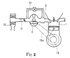
- Fig. 2 is a view showing even more generally the construction of an engine.
- the outboard engine 1 is equipped with an attached supercharging blower 3.
- This supercharging blower is connected to the crankshaft 16 of the engine 1, by which it is rotatably driven by the engine.
- the supercharging blower 3 is located between the intake manifold 5 and carburettor 31 of the engine.
- the bypass 32 is also located between the carburettor 31 and the intake manifold 5, and 33 in the Figure is an air cleaner.
- the outboard engine is not only easy to start with steady idling, as the ignition plug is not susceptible to damage with a four-stroke engine applied, but also it is driven in good and comfortable condition without causing water pollution or a foul odour with very little discharged hydrocarbons.
- the engine maintains a large amount of efficiency of air into the engine by using the supercharging blower 3, being capable of developing high power with the relatively small and light body.
- the supercharging blower 3 is located downstream of the carburettor 31, the air that is drawn into the carburettor through the air cleaner is mixed with fuel and then introduced into the supercharging blower 3, whereby the mixture is fully agitated and introduced into the intake manifold, thus keeping the mixture ratio in each cylinder in a good condition and developing great power.
- the mixing rate of gas in each cylinder has been different, sometimes causing unsteady rotation of the engine.
- the difference of the mixture ratio rate in each cylinder is 3 to 4 %, but in this embodiment with four cylinders, the difference is 0.2 to 0.4 % because the mixture is introduced into the engine after it has been mixed in the supercharging blower.
- Fig. 7 is a side view of thrust washer parts 23 and 24 of the outboard engine.
- the thrust washer parts to bear the load of the crankshaft 16 have been attached to in the cylinder block 2 of the crankshaft bearing and the bearing cap as shown in Fig. 9.
- the thrust washer in this engine is composed of the semicircular separate bits 23 and 24, which are different from each other in thickness as shown in the cross-sectional view in Fig. 8.
- the semicircular grooves 2a and 19a are made in the cylinder block 2 of the crankshaft bearing and the bearing cap 19.
- the grooves differ in depth according to the difference in their thickness.
- the thicker bit 23 is attached in the semicircular groove 2a in the cylinder block 2, and the touching surface 23a prevents the rotation by touching the surface 19b of the groove 19a in the bearing cap 19.
- the bit 24 is prevented from rotating by making the surface 24a touch the surface of 23a of the other bit 23.
- Fig. 3 is a cut-away side view showing a part of the outboard engine in the second embodiment.
- Fig. 4 is a cross-sectional view on line A-A of Fig. 3.
- This outboard engine is a four-cylinder gasoline engine 1, and downstream of the carburettor (not illustrated) is fixed the supercharging blower 3.
- the supercharging blower 3 is connected to each port of the cylinders through the intake manifold, through whose passages 6 mixture is introduced into the engine 1.
- the cooling water passage has a section as shown in Fig. 4 and is located around the intake manifold 5. Water from outboard is introduced into the cooling water passage through the water pipe 10 and the connecting hose 11 from the cooling water intake hole.
- the water is drawn in by the water pump 8 from outboard and introduced into the cooling water passage 7 and pumped outboard again through the outlet 0 after circulating and cooling mixture in each mixture-supplying passage 6 in the intake manifold.
- the mixture heated to about 110° C by the supercharging blower 3 is cooled by the cooling water passage 7.
- the process increases the power of the engine by about 5 % solving the problem of the supercharging blower itself in that the hot air or mixture heated to about 110° C with the compression by the supercharging blower attenuates the increase rate in power due to supercharging.
- the cooling of the supercharging blower is effected at low cost without much space and without any cooler attached.
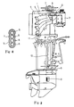
- Fig. 5 is a cross-sectional side view of a second embodiment of outboard engine.
- an oil pan needs to be attached for pooling lubricating oil for the engine 1, differing from the case of a two-stroke engine in which lubricating oil is mixed with fuel oil.
- the engine base 13 is attached under the oil pan 12 in such a way that the cooling water circulates along the wall of the oil pan over the engine base 13 through the oil-cooling water passage 14.
- the base of the oil-cooling water passage is connected to the water pipe 10, the water pump 8 and the cooling water inlet 9.
- the upper part of the oil-cooling water passage 14 is connected to the water hose 15, which leads to outboard by way of the engine 1.
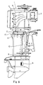
- Fig. 6 is a cross-sectional side view for showing a part of an outboard engine in the third embodiment.
- the oil filler hole attached at the lower end of the cylinder block 2 has been located on the cover of the cylinder head 4.
- the crankshaft of an engine is attached vertically, the cylinder head 4 is located at the rear of the engine.
- the lubricating oil filler hole is placed far on board, making it difficult to add lubricating oil, inspect the oil condition and keep the oil in proper level, increasing the possibility of the engine burning out.
- the oil filler hole for the lubricating oil is located at the upper part of the oil pan 12 fixed at the lower end of the cylinder block 2 so that it may be located at the side of the boat's hull body against the crankshaft 16, and to this supplying hole the inspection bar 18 is attached with screws. Therefore, the supply of lubricating oil to the oil pan of the engine 1 can be accomplished on board, and the inspection of the oil condition can also be done easily while on board, making it possible to supply the proper amount of oil. Thus the engine 1 is prevented from burning out, with a proper amount of lubricating oil always provided.
- the invention provides a four-stroke engine in an outboard motor assembly comprising the engine, a propeller, a drive shaft connecting the engine and propeller and means by which the assembly can be supported on the stern of a boat to operate as an outboard motor, with a particularly robust thrust washer assembly.
- the motor preferably has pivoting means by which the assembly can pivot about an upright axis for steering a driven boat and a steering handle and throttle control normally provided thereon.
Landscapes
- Engineering & Computer Science (AREA)
- General Engineering & Computer Science (AREA)
- Mechanical Engineering (AREA)
- Chemical & Material Sciences (AREA)
- Combustion & Propulsion (AREA)
- Ocean & Marine Engineering (AREA)
- Physics & Mathematics (AREA)
- Thermal Sciences (AREA)
- Lubrication Of Internal Combustion Engines (AREA)
- Lubrication Details And Ventilation Of Internal Combustion Engines (AREA)
- Cylinder Crankcases Of Internal Combustion Engines (AREA)
Claims (5)
- Moteur hors-bord comprenant:
un moteur quatre temps (1) comportant un vilebrequin (16) s'étendant sensiblement verticalement quand il tourne; et
une bague de butée (23, 24) montée sur des portions de palier formées sur un bloc-cylindre (2) et un chapeau de palier (19) du moteur, respectivement, pour supporter le vilebrequin, caractérisé en ce que ladite bague de butée est composé d'une paire de plaques semi-circulaires (23 et 24) présentant des épaisseurs différentes l'une de l'autre; en ce que lesdites plaques semi-circulaires sont reçues dans des gorges semi-circulaires (2a, 19a) qui sont formées sur lesdites portions de palier du bloc-cylindre et du chapeau de palier et qui présentent des profondeurs différentes l'une de l'autre, de manière que la surface correspondante de l'une (23) desdites plaques semicirculaires qui est d'épaisseur plus importante vienne en contact avec la surface d'extrémité de celle (2a) desdites gorges semi-circulaires dont la profondeur est la plus faible; et en ce qu'une soufflante de surcompression (3) est reliée au système d'admission de gaz de combustion du moteur. - Moteur hors-bord selon la revendication 1, dans lequel le surcompresseur est disposé entre un collecteur d'admission et un carburateur du moteur.
- Moteur hors-bord selon la revendication 1 ou 2, dans lequel le moteur quatre temps est équipé de passages d'eau de refroidissement de mélange circulant autour de la surface extérieure du collecteur d'admission situé entre le surcompresseur et les orifices de soupape des têtes de cylindre, et une pompe à eau pour envoyer l'eau de l'extérieur dans les passages d'eau.
- Moteur hors-bord selon la revendication 1, 2 ou 3, dans lequel le moteur est équipé d'une carter d'huile à l'extrémité inférieure du bloc-cylindre et des passages d'eau de refroidissement d'huile, disposés le long du carter d'huile, sont prévus pour faire circuler l'eau aspirée de l'extérieur par la ou par une pompe à eau.
- Moteur hors-bord selon la revendication 1, 2, 3 ou 4, dans lequel le moteur est équipé d'un carter d'huile fixé au fond du bloc-cylindre et comprend un trou de remplissage d'huile de lubrification à la partie supérieure du carter d'huile qui est situé près de la coque du bateau et contre le vilebrequin.
Applications Claiming Priority (4)
| Application Number | Priority Date | Filing Date | Title |
|---|---|---|---|
| JP16802888U JPH0287930U (fr) | 1988-12-26 | 1988-12-26 | |
| JP168028/88U | 1988-12-26 | ||
| JP129185/89U | 1989-11-04 | ||
| JP1989129185U JPH0721860Y2 (ja) | 1989-11-04 | 1989-11-04 | 船外機用内燃機関 |
Publications (2)
| Publication Number | Publication Date |
|---|---|
| EP0380883A1 EP0380883A1 (fr) | 1990-08-08 |
| EP0380883B1 true EP0380883B1 (fr) | 1993-06-09 |
Family
ID=26464662
Family Applications (1)
| Application Number | Title | Priority Date | Filing Date |
|---|---|---|---|
| EP89313502A Expired - Lifetime EP0380883B1 (fr) | 1988-12-26 | 1989-12-22 | Moteur hors-bord |
Country Status (3)
| Country | Link |
|---|---|
| US (1) | US5072707A (fr) |
| EP (1) | EP0380883B1 (fr) |
| AU (1) | AU621436B2 (fr) |
Families Citing this family (15)
| Publication number | Priority date | Publication date | Assignee | Title |
|---|---|---|---|---|
| EP0857861B1 (fr) | 1993-11-19 | 2002-04-03 | Honda Giken Kogyo Kabushiki Kaisha | Moteur à combustion interne |
| JPH08326676A (ja) * | 1995-06-05 | 1996-12-10 | Matsushita Electric Ind Co Ltd | 冷凍機用圧縮機 |
| US5829888A (en) * | 1997-09-08 | 1998-11-03 | General Motors Corporation | Thrust washer with integral retainer members |
| GB9823674D0 (en) * | 1998-10-30 | 1998-12-23 | Glacier Vandervell Ltd | Bearings |
| CA2401753A1 (fr) * | 2000-02-29 | 2001-09-07 | Norbert Korenjak | Moteur a quatre temps comportant un ensemble prise de force |
| US6408832B1 (en) * | 2001-03-26 | 2002-06-25 | Brunswick Corporation | Outboard motor with a charge air cooler |
| US6405692B1 (en) * | 2001-03-26 | 2002-06-18 | Brunswick Corporation | Outboard motor with a screw compressor supercharger |
| JP2004148917A (ja) * | 2002-10-29 | 2004-05-27 | Kawasaki Heavy Ind Ltd | 小型滑走艇 |
| US7134793B2 (en) * | 2004-08-11 | 2006-11-14 | Federal-Mogul Worldwide, Inc. | Thrust bearing assembly |
| KR20070111540A (ko) | 2005-03-14 | 2007-11-21 | 페더럴-모걸 코오포레이숀 | 통합적으로 바이어싱된 플랩 클로저를 가진 보호 시쓰 |
| US7354199B2 (en) * | 2005-06-01 | 2008-04-08 | Federal Mogul Worldwide, Inc. | Thrust bearing |
| US20100266229A1 (en) * | 2009-04-20 | 2010-10-21 | Solly Melyon | Aircraft Thrust Bearing Assembly, Method of Manufacture and Method of Use |
| DE102015005047A1 (de) | 2015-04-21 | 2016-10-27 | Neander Motors Ag | Sauganlage mit integriertem Ladelüftkühler |
| JP2018047867A (ja) * | 2016-09-23 | 2018-03-29 | ヤマハ発動機株式会社 | 船外機ユニットおよび船舶 |
| JP2018066277A (ja) * | 2016-10-17 | 2018-04-26 | ヤマハ発動機株式会社 | 船外機 |
Citations (1)
| Publication number | Priority date | Publication date | Assignee | Title |
|---|---|---|---|---|
| US4648351A (en) * | 1984-03-05 | 1987-03-10 | The Beth Israel Hospital Association | Animal cage insert and convertible animal cage |
Family Cites Families (10)
| Publication number | Priority date | Publication date | Assignee | Title |
|---|---|---|---|---|
| US3399161A (en) * | 1964-04-18 | 1968-08-27 | Asahi Chemical Ind | Process for preparing a solution of acrylonitrile polymers |
| DE2156704A1 (de) * | 1970-11-17 | 1972-05-18 | English Electric Diesels Ltd., Newton-le-Wollows, Lancashire (Großbritannien) | Wassergekühlte Brennkraftmaschine mit einem Lader |
| US4165720A (en) * | 1977-11-29 | 1979-08-28 | Barcak Joseph S | Fuel intake system for internal combustion engine |
| US4243010A (en) * | 1979-01-25 | 1981-01-06 | Zopfi Robert A | Supercharger apparatus with fixed baffle air-fuel mixture routing box |
| US4393852A (en) * | 1980-12-08 | 1983-07-19 | Eaton Corporation | Linkage mechanism for supercharger system |
| SE456921B (sv) * | 1983-06-21 | 1988-11-14 | Yanmar Diesel Engine Co | Vattenkyld utbordardieselmotor |
| US4611559A (en) * | 1983-09-13 | 1986-09-16 | Sanshin Kogyo Kabushiki Kaisha | Outboard motor provided with a four-stroke engine |
| JPH0639900B2 (ja) * | 1985-06-04 | 1994-05-25 | 三信工業株式会社 | 多気筒v型ターボエンジン |
| JPS61278494A (ja) * | 1985-06-05 | 1986-12-09 | Sanshin Ind Co Ltd | 船外機用タ−ボエンジン |
| NL8602971A (nl) * | 1986-11-24 | 1988-06-16 | Volvo Car Bv | Koelsysteem voor een turbocompressor. |
-
1989
- 1989-12-21 AU AU47050/89A patent/AU621436B2/en not_active Ceased
- 1989-12-22 EP EP89313502A patent/EP0380883B1/fr not_active Expired - Lifetime
- 1989-12-22 US US07/454,987 patent/US5072707A/en not_active Expired - Fee Related
Patent Citations (1)
| Publication number | Priority date | Publication date | Assignee | Title |
|---|---|---|---|---|
| US4648351A (en) * | 1984-03-05 | 1987-03-10 | The Beth Israel Hospital Association | Animal cage insert and convertible animal cage |
Non-Patent Citations (1)
| Title |
|---|
| "Bateaux" No 330, Nov 1985, Page 108: Moteurs Yamaha * |
Also Published As
| Publication number | Publication date |
|---|---|
| EP0380883A1 (fr) | 1990-08-08 |
| AU621436B2 (en) | 1992-03-12 |
| US5072707A (en) | 1991-12-17 |
| AU4705089A (en) | 1990-06-28 |
Similar Documents
| Publication | Publication Date | Title |
|---|---|---|
| EP0380883B1 (fr) | Moteur hors-bord | |
| JP2837685B2 (ja) | 4ストローク船外機の冷却装置 | |
| US5261356A (en) | Outboard motor | |
| US5637792A (en) | Exhaust gas sampler | |
| JP3879943B2 (ja) | 船外機 | |
| JP3225153B2 (ja) | 船外機用4サイクルエンジン | |
| US5037340A (en) | Lubricating device for four stroke outboard motor | |
| US6109231A (en) | Intake manifold for outboard motor | |
| US6537115B2 (en) | Oil pump construction for watercraft engine | |
| US6142842A (en) | Manifold arrangement for outboard motor | |
| US6213829B1 (en) | Component layout for outboard motor | |
| JPH10184337A (ja) | 船外機 | |
| US3800753A (en) | Drainage system for internal combustion engine having a horizontally disposed crankshaft | |
| US6044817A (en) | Camshaft and accessory drive arrangement for engine powering an outboard motor | |
| US7069895B2 (en) | Air intake system of outboard motor | |
| US20020193022A1 (en) | Cooling arrangement for outboard motor | |
| US6071159A (en) | Exhaust manifold for outboard motor | |
| JP2729686B2 (ja) | 2サイクル内燃機関のクランク室構造 | |
| JP4061970B2 (ja) | 2サイクルエンジン及び船外機 | |
| US5348499A (en) | Outboard motor | |
| JP4334720B2 (ja) | 筒内噴射式2サイクルエンジン | |
| JP3190505B2 (ja) | 船外機用4サイクルエンジンの吸気装置 | |
| JPH0515567Y2 (fr) | ||
| JPH10184474A (ja) | 船外機 | |
| JPS603464A (ja) | 船外機用内燃機関の冷却水導入路 |
Legal Events
| Date | Code | Title | Description |
|---|---|---|---|
| PUAI | Public reference made under article 153(3) epc to a published international application that has entered the european phase |
Free format text: ORIGINAL CODE: 0009012 |
|
| AK | Designated contracting states |
Kind code of ref document: A1 Designated state(s): GB IT |
|
| 17P | Request for examination filed |
Effective date: 19900912 |
|
| RIN1 | Information on inventor provided before grant (corrected) |
Inventor name: SANO, HARUO AICHI KIKAI KOGYO KABUSHIKI KAISHA Inventor name: TAKAI, KIICHIRO AICHI KIKAI KOGYO KABUSHIKI KAISHA |
|
| 17Q | First examination report despatched |
Effective date: 19910918 |
|
| GRAA | (expected) grant |
Free format text: ORIGINAL CODE: 0009210 |
|
| AK | Designated contracting states |
Kind code of ref document: B1 Designated state(s): GB IT |
|
| ITF | It: translation for a ep patent filed | ||
| PLBE | No opposition filed within time limit |
Free format text: ORIGINAL CODE: 0009261 |
|
| STAA | Information on the status of an ep patent application or granted ep patent |
Free format text: STATUS: NO OPPOSITION FILED WITHIN TIME LIMIT |
|
| 26N | No opposition filed | ||
| PGFP | Annual fee paid to national office [announced via postgrant information from national office to epo] |
Ref country code: GB Payment date: 19991222 Year of fee payment: 11 |
|
| PG25 | Lapsed in a contracting state [announced via postgrant information from national office to epo] |
Ref country code: GB Free format text: LAPSE BECAUSE OF NON-PAYMENT OF DUE FEES Effective date: 20001222 |
|
| GBPC | Gb: european patent ceased through non-payment of renewal fee |
Effective date: 20001222 |
|
| PG25 | Lapsed in a contracting state [announced via postgrant information from national office to epo] |
Ref country code: IT Free format text: LAPSE BECAUSE OF NON-PAYMENT OF DUE FEES;WARNING: LAPSES OF ITALIAN PATENTS WITH EFFECTIVE DATE BEFORE 2007 MAY HAVE OCCURRED AT ANY TIME BEFORE 2007. THE CORRECT EFFECTIVE DATE MAY BE DIFFERENT FROM THE ONE RECORDED. Effective date: 20051222 |