EP0380963A1 - Verfahren und Anlage zum kontinuierlichen Herstellen zellularer Gegenständen aus Latexschaum und dergleichen - Google Patents
Verfahren und Anlage zum kontinuierlichen Herstellen zellularer Gegenständen aus Latexschaum und dergleichen Download PDFInfo
- Publication number
- EP0380963A1 EP0380963A1 EP90100903A EP90100903A EP0380963A1 EP 0380963 A1 EP0380963 A1 EP 0380963A1 EP 90100903 A EP90100903 A EP 90100903A EP 90100903 A EP90100903 A EP 90100903A EP 0380963 A1 EP0380963 A1 EP 0380963A1
- Authority
- EP
- European Patent Office
- Prior art keywords
- plant
- fact
- layer
- foam
- plates
- Prior art date
- Legal status (The legal status is an assumption and is not a legal conclusion. Google has not performed a legal analysis and makes no representation as to the accuracy of the status listed.)
- Granted
Links
- 238000000034 method Methods 0.000 title claims abstract description 25
- 230000008569 process Effects 0.000 title claims abstract description 24
- 230000001413 cellular effect Effects 0.000 title claims abstract description 20
- 238000004519 manufacturing process Methods 0.000 title claims abstract description 20
- 229920001821 foam rubber Polymers 0.000 title claims abstract description 19
- 238000000465 moulding Methods 0.000 claims abstract description 34
- 239000006260 foam Substances 0.000 claims description 45
- 238000004073 vulcanization Methods 0.000 claims description 10
- 230000009471 action Effects 0.000 claims description 9
- 230000033001 locomotion Effects 0.000 claims description 7
- 239000000463 material Substances 0.000 claims description 7
- 230000035515 penetration Effects 0.000 claims description 7
- 239000007769 metal material Substances 0.000 claims description 3
- 238000000926 separation method Methods 0.000 claims description 2
- 238000002347 injection Methods 0.000 claims 1
- 239000007924 injection Substances 0.000 claims 1
- 238000005096 rolling process Methods 0.000 claims 1
- 239000000047 product Substances 0.000 description 13
- 239000012467 final product Substances 0.000 description 5
- 230000008859 change Effects 0.000 description 4
- 150000001875 compounds Chemical class 0.000 description 3
- 238000004132 cross linking Methods 0.000 description 3
- 229920001971 elastomer Polymers 0.000 description 3
- 230000000063 preceeding effect Effects 0.000 description 3
- 239000005060 rubber Substances 0.000 description 3
- 230000005540 biological transmission Effects 0.000 description 2
- 238000001035 drying Methods 0.000 description 2
- 239000012530 fluid Substances 0.000 description 2
- 238000010438 heat treatment Methods 0.000 description 2
- 230000001105 regulatory effect Effects 0.000 description 2
- 239000000126 substance Substances 0.000 description 2
- 229910000831 Steel Inorganic materials 0.000 description 1
- XAGFODPZIPBFFR-UHFFFAOYSA-N aluminium Chemical compound [Al] XAGFODPZIPBFFR-UHFFFAOYSA-N 0.000 description 1
- 229910052782 aluminium Inorganic materials 0.000 description 1
- 239000004411 aluminium Substances 0.000 description 1
- 230000008901 benefit Effects 0.000 description 1
- 230000015572 biosynthetic process Effects 0.000 description 1
- 229920000126 latex Polymers 0.000 description 1
- 239000004816 latex Substances 0.000 description 1
- 230000007246 mechanism Effects 0.000 description 1
- 229920003052 natural elastomer Polymers 0.000 description 1
- 229920001194 natural rubber Polymers 0.000 description 1
- 238000002360 preparation method Methods 0.000 description 1
- 238000007639 printing Methods 0.000 description 1
- 239000000344 soap Substances 0.000 description 1
- 239000010959 steel Substances 0.000 description 1
- 229920003051 synthetic elastomer Polymers 0.000 description 1
- 239000005061 synthetic rubber Substances 0.000 description 1
- 230000009466 transformation Effects 0.000 description 1
- 238000004804 winding Methods 0.000 description 1
Images


Classifications
-
- B—PERFORMING OPERATIONS; TRANSPORTING
- B29—WORKING OF PLASTICS; WORKING OF SUBSTANCES IN A PLASTIC STATE IN GENERAL
- B29C—SHAPING OR JOINING OF PLASTICS; SHAPING OF MATERIAL IN A PLASTIC STATE, NOT OTHERWISE PROVIDED FOR; AFTER-TREATMENT OF THE SHAPED PRODUCTS, e.g. REPAIRING
- B29C37/00—Component parts, details, accessories or auxiliary operations, not covered by group B29C33/00 or B29C35/00
- B29C37/0003—Discharging moulded articles from the mould
-
- B—PERFORMING OPERATIONS; TRANSPORTING
- B29—WORKING OF PLASTICS; WORKING OF SUBSTANCES IN A PLASTIC STATE IN GENERAL
- B29C—SHAPING OR JOINING OF PLASTICS; SHAPING OF MATERIAL IN A PLASTIC STATE, NOT OTHERWISE PROVIDED FOR; AFTER-TREATMENT OF THE SHAPED PRODUCTS, e.g. REPAIRING
- B29C44/00—Shaping by internal pressure generated in the material, e.g. swelling or foaming ; Producing porous or cellular expanded plastics articles
- B29C44/20—Shaping by internal pressure generated in the material, e.g. swelling or foaming ; Producing porous or cellular expanded plastics articles for articles of indefinite length
- B29C44/30—Expanding the moulding material between endless belts or rollers
-
- B—PERFORMING OPERATIONS; TRANSPORTING
- B29—WORKING OF PLASTICS; WORKING OF SUBSTANCES IN A PLASTIC STATE IN GENERAL
- B29C—SHAPING OR JOINING OF PLASTICS; SHAPING OF MATERIAL IN A PLASTIC STATE, NOT OTHERWISE PROVIDED FOR; AFTER-TREATMENT OF THE SHAPED PRODUCTS, e.g. REPAIRING
- B29C44/00—Shaping by internal pressure generated in the material, e.g. swelling or foaming ; Producing porous or cellular expanded plastics articles
- B29C44/34—Auxiliary operations
- B29C44/60—Measuring, controlling or regulating
-
- B—PERFORMING OPERATIONS; TRANSPORTING
- B29—WORKING OF PLASTICS; WORKING OF SUBSTANCES IN A PLASTIC STATE IN GENERAL
- B29K—INDEXING SCHEME ASSOCIATED WITH SUBCLASSES B29B, B29C OR B29D, RELATING TO MOULDING MATERIALS OR TO MATERIALS FOR MOULDS, REINFORCEMENTS, FILLERS OR PREFORMED PARTS, e.g. INSERTS
- B29K2021/00—Use of unspecified rubbers as moulding material
-
- B—PERFORMING OPERATIONS; TRANSPORTING
- B29—WORKING OF PLASTICS; WORKING OF SUBSTANCES IN A PLASTIC STATE IN GENERAL
- B29L—INDEXING SCHEME ASSOCIATED WITH SUBCLASS B29C, RELATING TO PARTICULAR ARTICLES
- B29L2031/00—Other particular articles
- B29L2031/737—Articles provided with holes, e.g. grids, sieves
-
- B—PERFORMING OPERATIONS; TRANSPORTING
- B29—WORKING OF PLASTICS; WORKING OF SUBSTANCES IN A PLASTIC STATE IN GENERAL
- B29L—INDEXING SCHEME ASSOCIATED WITH SUBCLASS B29C, RELATING TO PARTICULAR ARTICLES
- B29L2031/00—Other particular articles
- B29L2031/751—Mattresses, cushions
Definitions
- the present invention is directed to a process and plant for continuously manufacturing cellular products of latex foam or the like and more specifically the invention is directed to the manufacture of cellular mattresses and cushions.
- the known processes are based substantially on the use of moulds constituted by a case and a lid whose inner surface is provided with a plurality of protuberances corresponding to the shape of the cells of the desired product.
- the cavity of the mould filled with latex foam is heated by circulating steam under pressure in suitable air spaces so as to transfer the heat necessary for the vulcanizing process either to the metallic walls or to the metallic protuberances around and through the foam.
- the final product can show inadequate characteristics of capacity load or lifetime and this for a good part owing to a possible insufficient vulcanization of some parts inside the spongy mass.
- the cavities delimited by the surfaces of the protuberances are closed at the base by an appropriate plate whose tightness can result not sufficient and permit thus during the vulcanizing step the entry of superheated steam inside the cavities.
- the various protuberances heat in a different manner the surrounding foam mass wherein they penetrate originating consequently a different cross-linking from one zone to another with the drawback of producing localized less cured zones, i.e. zones more exposed to tears, for instance in a cellular mattress in consequence of various folding cycles.
- mould processes are not suitable for manufacturing cellular products of different dimensions.
- a process for continuously manufacturing not cellular products of latex foam is also known.
- the known process is accomplished by placing on a steel strip moving continuously a foam layer that gradually is vulcanized by passing through a tunnel heated with steam under pressure.
- the continuous layer is cut transversely of its length into several single pieces subjected then to the drying step to draw off soaps and like substances usually added to the latex compound at the beginning.
- the cited process is used for manufacturing layers of latex foam of very reduced thickness, generally of 4 - 5 cm, and cannot be utilized for manufacturing mattresses usually having thicknesses comprised between 14 and 18 cm.
- the aim of the present invention is a process and plant, both devoid of all the previously cited drawbacks.
- the object of the present invention is a process for manufactruring cellular products, of latex foam and the like, in the form of a continuous layerto be divided into single pieces, said process comprising the following steps: - to advance a laying surface between two stations, first and second, respectively; - to place in proximity of the first station on the laying surface the latex foam for a pre-determined height and to form a continuous layer delimited by a first face in contact with said laying surface, by a second face opposite to the first one, by two sides; - to vulcanize the latex foam between the two stations; said process being characterized by the fact of: - moulding a plurality of open cells on the surface of the second face between said first and second station through the layer of foam already laid and in direction perpendicular to the two faces; - vulcanizing the foam layer by supplying heat around the layer and through the cells.
- the process is characterized by the fact of advancing in a continuous manner the said laying surface and of moulding said plurality of cells in direction perpendicular to the faces of the layer.
- the process can be characterized by the fact of advancing the laying surface with an intermittent motion and of moulding a plurality of cells perpendicularly to said faces of the layer when said surface is still.
- the vulcanization can be carried out by supplying heat to the cells in any whatsoever manner, among other things by means of a heating fluid, for instance preferably steam under pressure.
- a heating fluid for instance preferably steam under pressure.
- a further object of the invention is a plant for manufacturing cellular products, of latex foam or the like, in the form of a continuous layer to be divided into single pieces, said plant comprising: - a laying surface moving forward between a first and a second station; - motive means for advancing said laying surface; - a device for placing and forming a layer of foam in proximity of the first station, said layer being delimited by a first face in contact with the laying surface, by a second face opposite to the first one and by two sides; - a vulcanizer positioned between the two stations; said plant being characterized by the fact of comprising moulding and driving means, said moulding means being constituted by a base surface provided with a plurality of projecting protuberances having the same shape as the cells to be moulded, said protuberances at least in a place comprised between the said two stations being oriented in direction perpendicular to the faces of said layer, said driving means moving the said base surface from a rest position wherein the protu
- the plant for manufacturing a continuous layer 1 is now described.
- the said continuous layer 1 is divisible into single mattresses provided with cells 2 and delimited externally and internally by faces 3 and 4 and laterally by the sides 5 and 6.
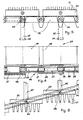
- Figure 2 shows in its more general aspect a plant 7 for manufacturing the continuous layer 1 of figure 1.
- the plant 7 comprises a rubber conveyor belt 8 moving forward continuously between two stations, a first station 9 and a second station 10, respectively, a device 12 for placing the foam layer in proximity of the first station, a tunnel vulcanizer 13 making use of steam under pressure, means 14 for moulding the cells 2, means for setting in action the moulding means which will be explained hereinafter.
- the conveyor belt is rotate through pulleys 11, 11′.
- the conveyor belt 8 comprises lips 8′ between the stations 9 and 10 deformed upwards by the action of rollers 15 and 16 idle applied around their axes of rotation.
- the lips 8′ form the lateral walls apt to define the sides 5 and 6 of the continuous layer 1.
- the moulding means 14 in the more general aspects of the present invention are mainly constituted by a base surface 17 making part of an annular structure rotating continuously by means of rotating means, a driving rotating means 19 and a driven rotating means 20, respectively, and by substantially conical protuberances 21 projecting from the base surface 17 and having inner cavities open on the base surface itself.
- the moulding means 17 (figure 3) comprise a plurality of rigid plates 22, each one having projecting protuberances 21, a conveyer 23 comprised between two rotating means represented by toothed wheels, means for connecting the plates 22 to the conveyer 23, moving means of the conveyer for moving the plates 22 between a first and a second station, means for driving and guiding the plates to graduate the approaching and the separation of the protuberances 21 from the surface where the latex foam is laid.
- the conveyer 23 is constituted by a plurality of slats 24 independent of one another and placed side by side; the slats are laterally connected to articulated joints 25 of two chains one of which is indicated with reference numeral 26 in figure 4.
- the lateral chains constitute the moving means of the conveyer 23 and each chain meshes with two toothed wheels, a driving toothed wheel and a driven toothed wheel, respectively.
- Each chain 26 (figure 4) is formed by links 27 connected to one another through the articulated joints 25 and more detailed each link 27 is constituted by two straps 28 separated from each other by the articulated joints 25 to which they are hinged.
- the links 27 form empty spaces at the inside of which the teeth 29 of each toothed wheel pass during the winding of the chains on the toothed wheels (figure 5).
- the slats 24 of the conveyer 23 comprise at the appropriate sides prolongations 30 of the articulated joints 25 inserted in suitable guides 31 of the fixed structure (figures 6, 7).
- the means for connecting the plates 22 to the conveyer 23 (figures 6, 7) comprise at least a pair of stems 32 projecting from the surface of each plate 22 opposite to that from which the protuberances 21 project and also corresponding holes 33 crossed by the cited stems, obtained on the slats 24 of the conveyer 23.
- the free ends of the stems 32 are provided with stop parts 34 having an area greater than that of the hole 33 crossed by the stem.
- said stop parts can be formed by a threaded disc that may be screwed on the stem to vary, thanks to the ability of this latter to go down more or less, the depth of the cell 2 formed in the foam layer 1 (figure 1).
- the driving means of the plate 22 comprise on their turn lateral pins 35 and grooved guides 36 for housing the pins 35.
- the guides 36 are arranged, respectively, between the exit of the driven toothed wheel 20 and the surface for laying the foam constituted by the conveyor belt 8 and between the surface for laying the foam and the entrance of the driving toothed wheel.
- Figure 8 shows one of the lateral guides of the means for setting in action the plates.
- the guide is arranged between the driven toothed wheel 20 and the surface of the conveyor belt 8 and as shown by figure 8 the lateral pin 35 of each plate 22 is inserted in the corresponding groove of the guide 36 and travels along a gradual inclination portion between the toothed wheel 20 and the laying surface of the foam.
- the annular structure is set in action at the same surface speed as the conveyor belt and is made in such a way as to be tangent to the belt in the portion comprised between the stations 9 and 10 (figure 1).
- the foam layer is then laid in proximity of the station 9 by means of the device 12 provided in a known way with a foam injector arranged transversely of the advancing direction of the rubber conveyor belt 8 now in one sense, now in opposite sense.
- the height of the layer is regulated by a levelling element, known as blade 12′, arranged immediately down line of the device 12.
- the foam layer already levelled on the conveyor belt 8 is directed towards the station 10 being subject before entering in the vulcanizer 13 to the penetration of the protuberances apt to the moulding of the cells 2.
- the various plates 22 provided with the protuberances 21 are always integral with the conveyer 23 both in the upper branch and in the lower branch thanks to the presence of the stems 32 passing through the holes of the conveyer 23.
- the approaching of the protuberances 21 to the continuous layer 1 is graduated with a law imposed by the inclination of the guides 36 with respect to the conveyor belt 8.
- stems 32 slide perpendicularly to the slats 24 of the conveyer 23 whose lower branch is stretched between the two toothed wheels 19 and 20 and is directed parallely to the conveyor belt 8 at the same speed.
- the distance between the outer surface of the plate 22 and the outermost face of the foam layer 1 in movement is greater than the height of the protuberances 21 on the plate 22 and anyhow in any solution is at least equal to the height of the protuberances.
- the cited characteristics guarantee the gradual and complete penetration of the protuberances 21 always in direction perpendicular to the faces of the layer itself.
- the layer already provided with cells passes little by little through the tunnel vulcanizer 13 receiving the heat necessary to the cross-linking of the foam mass by means of the steam under pressure.
- the continuous layer is then removed gradually passing through a pair of rollers set in action with a surface speed equal to the approach speed of the belt.
- figure 2 shows two drawing rollers 37 of the layer 1.
- the layer Downstream of the cited rollers, the layer is cut according to successive transversal lines of which two adjacent are at a distance from each other corresponding to the width of the single mattress.
- each length is subject to the usual drying step.
- the plant could comprise a different system for driving and guiding the plates 22 in order to obtain the gradual penetration of the protuberances 21 perpendicularly to the layer 1.
- the same plates could be provided with lateral rollers inserted in corresponding grooves of the fixed frame.
- the surface for laying the foam could be constituted instead of rubber belts by belts of flexible polymeric material or different materials on condition that they are suitable for bearing the foam layer between the two stations 9 and 10 (figure 1).
- the conveyor belt 8 could be made of metallic material to favour the transmission of heat during vulcanization.
- a belt provided with a flat laying surface could be associated to two lateral walls extending in the portion comprised between the two stations 9 and 10.
- the two lateral walls should be at a distance from each other equal to the length desired for the single mattress and very advantageously one of the walls could be moved with respect to the other in case it is wished to vary the length of the single mattress.
- the means for moulding the cells could assume realizations and shapes different from those described, disposing always in any solution groups of plates or successive strips provided with relative protuberances and associating said strips to a conveyor track or like element.
- both the plates 22 and the protuberances 21 could be made up of different materials, as for example metallic materials, preferably of aluminium for a good transmission of heat to the mass of foam during the vulcanization.
- the surface of the conveyor belt could be provided with ribs or like elements arranged with particular geometry in order to determine on the foam layer in contact with the belt a pre-determined imprinting apt to appear on the outer face of the final product.
- the present invention achieves all the aimed purposes.
- the vulcanization of the continuous layer is carried out by supplying heat by means of a heating fluid either all around the layer or inside the cells of the layer.
- the heat passes inside the cells thanks to the presence of protuberances 21 open at the base, for instance at the plate 22 to which they are connected.
- the vulcanization is uniform for the whole layer. Therefore no zone is localized inside the foam wherein the cross-linking is less than that of other zones with a consequent lower resistance of said zone in the finished product.
- the characteristics of the present invention permit to avoid the formation of a final product with not desired imprintings on the outer face.
- the manufacture of the layer according to the invention permits to obtain products different from one another for dimensional variations without making recourse to substantial variations in the process and plant.
- the cited result gives the advantage of regulating geometrically the capacity load of the mattress without making recourse to physical variations of the compound, for instance as it could be made with variations of the density of the foam obtainable only with complicated and long preparation and measuring steps of the compound.
- the invention includes in its scope any other alternative embodiment accessible to a technician of the field; for example, the method and plant of the invention can be utilized for manufacturing cellular layers of latex foam either of natural or synthetic rubber, or continuous cellular layers of materials corresponding to those cited and divisible then into single products as mattresses, cushions or other cellular products for home, sanitary, civil and military use.
Landscapes
- Manufacture Of Porous Articles, And Recovery And Treatment Of Waste Products (AREA)
- Casting Or Compression Moulding Of Plastics Or The Like (AREA)
- Heating, Cooling, Or Curing Plastics Or The Like In General (AREA)
- Hydroponics (AREA)
Applications Claiming Priority (2)
| Application Number | Priority Date | Filing Date | Title |
|---|---|---|---|
| IT1923989 | 1989-01-30 | ||
| IT8919239A IT1229513B (it) | 1989-01-30 | 1989-01-30 | Procedimento e impianto per la fabbricazione in continuo di prodotti alveolati in schiuma da lattice e simili |
Publications (2)
| Publication Number | Publication Date |
|---|---|
| EP0380963A1 true EP0380963A1 (de) | 1990-08-08 |
| EP0380963B1 EP0380963B1 (de) | 1994-09-07 |
Family
ID=11156028
Family Applications (1)
| Application Number | Title | Priority Date | Filing Date |
|---|---|---|---|
| EP90100903A Expired - Lifetime EP0380963B1 (de) | 1989-01-30 | 1990-01-17 | Verfahren und Anlage zum kontinuierlichen Herstellen zellularer Gegenständen aus Latexschaum und dergleichen |
Country Status (6)
| Country | Link |
|---|---|
| EP (1) | EP0380963B1 (de) |
| AT (1) | ATE111021T1 (de) |
| DE (1) | DE69012155T2 (de) |
| DK (1) | DK171464B1 (de) |
| ES (1) | ES2063843T3 (de) |
| IT (1) | IT1229513B (de) |
Cited By (6)
| Publication number | Priority date | Publication date | Assignee | Title |
|---|---|---|---|---|
| US6086802A (en) * | 1998-04-16 | 2000-07-11 | Sapsa Bedding S.P.A. | Process and plant for manufacture of latex foam products |
| US6312244B1 (en) | 1998-04-16 | 2001-11-06 | Sapsa Bedding Spa | Plant for manufacture of foam products |
| EP1361033A3 (de) * | 2002-05-09 | 2004-03-10 | Sapsa Bedding S.R.L. | Verfahren und Anlage zur Bildung einer kontinuierlichen Schaumstoffschicht |
| US7604761B2 (en) | 2006-05-11 | 2009-10-20 | Sapsa Bedding Srl | Process and plant for continuous manufacture of latex foam articles |
| EP2072209A3 (de) * | 2007-12-18 | 2010-11-24 | Sapsa Bedding S.R.L. | Werk zur kontinuierlichen Herstellung einer Schaumschicht zur Bildung von Stützartikeln |
| US7842206B2 (en) | 2006-04-04 | 2010-11-30 | Sapsa Bedding Srl | Process and plant for continuous manufacture of resting articles of latex foam |
Families Citing this family (3)
| Publication number | Priority date | Publication date | Assignee | Title |
|---|---|---|---|---|
| AU2003902499A0 (en) * | 2003-05-22 | 2003-06-05 | Scott Messenger | A conveyor belt |
| CN100537181C (zh) * | 2007-05-31 | 2009-09-09 | 李广明 | 一种乳胶发泡制品生产装置 |
| CN100575043C (zh) * | 2007-05-31 | 2009-12-30 | 李广明 | 一种连续生产乳胶发泡制品的链板 |
Citations (5)
| Publication number | Priority date | Publication date | Assignee | Title |
|---|---|---|---|---|
| US2757415A (en) * | 1951-05-05 | 1956-08-07 | Gen Motors Corp | Method of molding articles from foamed latex |
| US2905970A (en) * | 1952-12-03 | 1959-09-29 | Dayton Rubber Company | Mold pin construction |
| US3076226A (en) | 1960-02-17 | 1963-02-05 | Us Rubber Co | Apparatus for making sheets of foam rubber |
| US3081496A (en) * | 1959-10-15 | 1963-03-19 | John F Moore | Method of forming flexible sheets of cured foamed rubber |
| US4149840A (en) * | 1977-11-08 | 1979-04-17 | Tippmann Eugene R | Apparatus for producing rigid foam plastic insulating panels |
-
1989
- 1989-01-30 IT IT8919239A patent/IT1229513B/it active
-
1990
- 1990-01-17 AT AT90100903T patent/ATE111021T1/de not_active IP Right Cessation
- 1990-01-17 DE DE69012155T patent/DE69012155T2/de not_active Expired - Fee Related
- 1990-01-17 ES ES90100903T patent/ES2063843T3/es not_active Expired - Lifetime
- 1990-01-17 EP EP90100903A patent/EP0380963B1/de not_active Expired - Lifetime
- 1990-01-30 DK DK024790A patent/DK171464B1/da not_active IP Right Cessation
Patent Citations (5)
| Publication number | Priority date | Publication date | Assignee | Title |
|---|---|---|---|---|
| US2757415A (en) * | 1951-05-05 | 1956-08-07 | Gen Motors Corp | Method of molding articles from foamed latex |
| US2905970A (en) * | 1952-12-03 | 1959-09-29 | Dayton Rubber Company | Mold pin construction |
| US3081496A (en) * | 1959-10-15 | 1963-03-19 | John F Moore | Method of forming flexible sheets of cured foamed rubber |
| US3076226A (en) | 1960-02-17 | 1963-02-05 | Us Rubber Co | Apparatus for making sheets of foam rubber |
| US4149840A (en) * | 1977-11-08 | 1979-04-17 | Tippmann Eugene R | Apparatus for producing rigid foam plastic insulating panels |
Cited By (9)
| Publication number | Priority date | Publication date | Assignee | Title |
|---|---|---|---|---|
| US6086802A (en) * | 1998-04-16 | 2000-07-11 | Sapsa Bedding S.P.A. | Process and plant for manufacture of latex foam products |
| US6312244B1 (en) | 1998-04-16 | 2001-11-06 | Sapsa Bedding Spa | Plant for manufacture of foam products |
| EP1361033A3 (de) * | 2002-05-09 | 2004-03-10 | Sapsa Bedding S.R.L. | Verfahren und Anlage zur Bildung einer kontinuierlichen Schaumstoffschicht |
| US6998077B2 (en) | 2002-05-09 | 2006-02-14 | Sapsa Bedding S.R.L. | Process and plant for continuous manufacture of a foam layer |
| US7326040B2 (en) | 2002-05-09 | 2008-02-05 | Sapsa Bedding S.R.L. | Process and plant for continuous manufacture of a foam layer |
| US7842206B2 (en) | 2006-04-04 | 2010-11-30 | Sapsa Bedding Srl | Process and plant for continuous manufacture of resting articles of latex foam |
| US7604761B2 (en) | 2006-05-11 | 2009-10-20 | Sapsa Bedding Srl | Process and plant for continuous manufacture of latex foam articles |
| EP2072209A3 (de) * | 2007-12-18 | 2010-11-24 | Sapsa Bedding S.R.L. | Werk zur kontinuierlichen Herstellung einer Schaumschicht zur Bildung von Stützartikeln |
| US8087917B2 (en) | 2007-12-18 | 2012-01-03 | Sapsa Bedding Srl | Plant for continuously manufacturing a foam layer to form rest articles |
Also Published As
| Publication number | Publication date |
|---|---|
| DE69012155T2 (de) | 1995-02-02 |
| DE69012155D1 (de) | 1994-10-13 |
| EP0380963B1 (de) | 1994-09-07 |
| DK24790A (da) | 1990-07-31 |
| IT1229513B (it) | 1991-09-03 |
| IT8919239A0 (it) | 1989-01-30 |
| ES2063843T3 (es) | 1995-01-16 |
| DK171464B1 (da) | 1996-11-11 |
| DK24790D0 (da) | 1990-01-30 |
| ATE111021T1 (de) | 1994-09-15 |
Similar Documents
| Publication | Publication Date | Title |
|---|---|---|
| US5229138A (en) | System for continuous manufacture of cellular products such as latex foam mattresses, cushions or the like | |
| US6312244B1 (en) | Plant for manufacture of foam products | |
| US3507010A (en) | Continuous molding of thermoplastic materials | |
| EP0380963B1 (de) | Verfahren und Anlage zum kontinuierlichen Herstellen zellularer Gegenständen aus Latexschaum und dergleichen | |
| US6086802A (en) | Process and plant for manufacture of latex foam products | |
| EP0153049B1 (de) | Verfahren zur Herstellung doppeltverzahnter Riemen | |
| US7326040B2 (en) | Process and plant for continuous manufacture of a foam layer | |
| US3973894A (en) | Device for the production of toothed belts | |
| US4861403A (en) | Method of fabricating a double-toothed belt | |
| US5035846A (en) | System and process for continuous manufacture of cellular products such as latex foam mattresses, cushions or the like | |
| US3516116A (en) | Device and a process for continuously forming a sheet of thermoplastic material | |
| US4575445A (en) | Method of manufacture of long cogged V-belts | |
| JPH01156022A (ja) | 長尺コグ付きvベルトの製造方法 | |
| US6284180B1 (en) | Method to cure endless track belts and apparatus therefor | |
| JP3326414B2 (ja) | コグ付きvベルトの製造方法およびその製造装置 | |
| EP0145501B1 (de) | Verfahren und Vorrichtung zur Herstellung langer gezahnter Antriebsriemen | |
| JPH0123783Y2 (de) | ||
| JPS60129218A (ja) | 長尺コグ付きvベルトの製造方法 | |
| KR100478406B1 (ko) | 다수의 돌기부를 갖는 보드의 제조장치 및 제조방법 | |
| CA2290462C (en) | Improved method to cure endless track belts and apparatus therefor | |
| JPS6348686B2 (de) | ||
| JPS591174B2 (ja) | 形材連続製造方法 | |
| JPS6317034A (ja) | ダブルタイミングベルトの製造法 | |
| CS231846B1 (cs) | Zařízení na výrobu klínových řemenů | |
| NO300360B1 (no) | Anordning ved et produksjonsanlegg for fremstilling av latexprodukter |
Legal Events
| Date | Code | Title | Description |
|---|---|---|---|
| PUAI | Public reference made under article 153(3) epc to a published international application that has entered the european phase |
Free format text: ORIGINAL CODE: 0009012 |
|
| AK | Designated contracting states |
Kind code of ref document: A1 Designated state(s): AT BE CH DE ES FR GB LI NL |
|
| 17P | Request for examination filed |
Effective date: 19900913 |
|
| 17Q | First examination report despatched |
Effective date: 19920327 |
|
| RAP1 | Party data changed (applicant data changed or rights of an application transferred) |
Owner name: PIRELLI S.P.A. |
|
| RAP1 | Party data changed (applicant data changed or rights of an application transferred) |
Owner name: SAPSA BEDDING S.P.A. |
|
| GRAA | (expected) grant |
Free format text: ORIGINAL CODE: 0009210 |
|
| AK | Designated contracting states |
Kind code of ref document: B1 Designated state(s): AT BE CH DE ES FR GB LI NL |
|
| REF | Corresponds to: |
Ref document number: 111021 Country of ref document: AT Date of ref document: 19940915 Kind code of ref document: T |
|
| REF | Corresponds to: |
Ref document number: 69012155 Country of ref document: DE Date of ref document: 19941013 |
|
| REG | Reference to a national code |
Ref country code: ES Ref legal event code: FG2A Ref document number: 2063843 Country of ref document: ES Kind code of ref document: T3 |
|
| ET | Fr: translation filed | ||
| PLBE | No opposition filed within time limit |
Free format text: ORIGINAL CODE: 0009261 |
|
| STAA | Information on the status of an ep patent application or granted ep patent |
Free format text: STATUS: NO OPPOSITION FILED WITHIN TIME LIMIT |
|
| 26N | No opposition filed | ||
| REG | Reference to a national code |
Ref country code: FR Ref legal event code: CA |
|
| REG | Reference to a national code |
Ref country code: CH Ref legal event code: PFA Free format text: SAPSA BEDDING S.P.A.,VIALE RIMEMBRANZE, 62,SESTO SAN GIOVANNI (MILANO) (IT) TRANSFER- SAPSA BEDDING S.P.A.,PALAZZO DEI CONGRESSI STRADA 1-MILANOFIORI,20090 ASSAGO (MI) (IT) |
|
| REG | Reference to a national code |
Ref country code: GB Ref legal event code: IF02 |
|
| NLS | Nl: assignments of ep-patents |
Owner name: SAPSA BEDDING S.R.L. |
|
| REG | Reference to a national code |
Ref country code: FR Ref legal event code: CJ Ref country code: FR Ref legal event code: CD |
|
| REG | Reference to a national code |
Ref country code: CH Ref legal event code: PFA Free format text: SAPSA BEDDING S.P.A. TRANSFER- SAPSA BEDDING S.R.L. |
|
| PGFP | Annual fee paid to national office [announced via postgrant information from national office to epo] |
Ref country code: ES Payment date: 20080128 Year of fee payment: 19 Ref country code: CH Payment date: 20080130 Year of fee payment: 19 |
|
| PGFP | Annual fee paid to national office [announced via postgrant information from national office to epo] |
Ref country code: NL Payment date: 20080124 Year of fee payment: 19 Ref country code: GB Payment date: 20080129 Year of fee payment: 19 |
|
| PGFP | Annual fee paid to national office [announced via postgrant information from national office to epo] |
Ref country code: AT Payment date: 20080102 Year of fee payment: 19 |
|
| PGFP | Annual fee paid to national office [announced via postgrant information from national office to epo] |
Ref country code: DE Payment date: 20080229 Year of fee payment: 19 Ref country code: FR Payment date: 20080117 Year of fee payment: 19 |
|
| PGFP | Annual fee paid to national office [announced via postgrant information from national office to epo] |
Ref country code: BE Payment date: 20080206 Year of fee payment: 19 |
|
| REG | Reference to a national code |
Ref country code: CH Ref legal event code: PL |
|
| GBPC | Gb: european patent ceased through non-payment of renewal fee |
Effective date: 20090117 |
|
| NLV4 | Nl: lapsed or anulled due to non-payment of the annual fee |
Effective date: 20090801 |
|
| PG25 | Lapsed in a contracting state [announced via postgrant information from national office to epo] |
Ref country code: DE Free format text: LAPSE BECAUSE OF NON-PAYMENT OF DUE FEES Effective date: 20090801 Ref country code: AT Free format text: LAPSE BECAUSE OF NON-PAYMENT OF DUE FEES Effective date: 20090117 Ref country code: CH Free format text: LAPSE BECAUSE OF NON-PAYMENT OF DUE FEES Effective date: 20090131 Ref country code: LI Free format text: LAPSE BECAUSE OF NON-PAYMENT OF DUE FEES Effective date: 20090131 |
|
| REG | Reference to a national code |
Ref country code: FR Ref legal event code: ST Effective date: 20091030 |
|
| PG25 | Lapsed in a contracting state [announced via postgrant information from national office to epo] |
Ref country code: GB Free format text: LAPSE BECAUSE OF NON-PAYMENT OF DUE FEES Effective date: 20090117 Ref country code: NL Free format text: LAPSE BECAUSE OF NON-PAYMENT OF DUE FEES Effective date: 20090801 |
|
| PG25 | Lapsed in a contracting state [announced via postgrant information from national office to epo] |
Ref country code: BE Free format text: LAPSE BECAUSE OF NON-PAYMENT OF DUE FEES Effective date: 20090131 |
|
| REG | Reference to a national code |
Ref country code: ES Ref legal event code: FD2A Effective date: 20090119 |
|
| PG25 | Lapsed in a contracting state [announced via postgrant information from national office to epo] |
Ref country code: FR Free format text: LAPSE BECAUSE OF NON-PAYMENT OF DUE FEES Effective date: 20090202 Ref country code: ES Free format text: LAPSE BECAUSE OF NON-PAYMENT OF DUE FEES Effective date: 20090119 |