EP0381084B1 - Paroi de séparation pour broyeur tubulaire - Google Patents
Paroi de séparation pour broyeur tubulaire Download PDFInfo
- Publication number
- EP0381084B1 EP0381084B1 EP90101618A EP90101618A EP0381084B1 EP 0381084 B1 EP0381084 B1 EP 0381084B1 EP 90101618 A EP90101618 A EP 90101618A EP 90101618 A EP90101618 A EP 90101618A EP 0381084 B1 EP0381084 B1 EP 0381084B1
- Authority
- EP
- European Patent Office
- Prior art keywords
- tube mill
- partition according
- anyone
- air passage
- rear wall
- Prior art date
- Legal status (The legal status is an assumption and is not a legal conclusion. Google has not performed a legal analysis and makes no representation as to the accuracy of the status listed.)
- Expired - Lifetime
Links
- 238000000638 solvent extraction Methods 0.000 title 1
- 238000005192 partition Methods 0.000 claims description 42
- 239000000463 material Substances 0.000 claims description 22
- 238000011144 upstream manufacturing Methods 0.000 claims description 6
- 229910000831 Steel Inorganic materials 0.000 claims description 5
- 239000010959 steel Substances 0.000 claims description 5
- 238000006073 displacement reaction Methods 0.000 claims description 2
- 238000012423 maintenance Methods 0.000 description 5
- 230000000694 effects Effects 0.000 description 4
- 230000001105 regulatory effect Effects 0.000 description 3
- 238000000227 grinding Methods 0.000 description 2
- 239000002184 metal Substances 0.000 description 2
- 229910000639 Spring steel Inorganic materials 0.000 description 1
- 230000002411 adverse Effects 0.000 description 1
- 238000004140 cleaning Methods 0.000 description 1
- 230000000295 complement effect Effects 0.000 description 1
- 239000011365 complex material Substances 0.000 description 1
- 238000010276 construction Methods 0.000 description 1
- 230000006735 deficit Effects 0.000 description 1
- 230000002349 favourable effect Effects 0.000 description 1
- 238000009434 installation Methods 0.000 description 1
- 238000003801 milling Methods 0.000 description 1
- 230000002093 peripheral effect Effects 0.000 description 1
- 230000011218 segmentation Effects 0.000 description 1
- 238000009423 ventilation Methods 0.000 description 1
Images
Classifications
-
- B—PERFORMING OPERATIONS; TRANSPORTING
- B02—CRUSHING, PULVERISING, OR DISINTEGRATING; PREPARATORY TREATMENT OF GRAIN FOR MILLING
- B02C—CRUSHING, PULVERISING, OR DISINTEGRATING IN GENERAL; MILLING GRAIN
- B02C17/00—Disintegrating by tumbling mills, i.e. mills having a container charged with the material to be disintegrated with or without special disintegrating members such as pebbles or balls
- B02C17/04—Disintegrating by tumbling mills, i.e. mills having a container charged with the material to be disintegrated with or without special disintegrating members such as pebbles or balls with unperforated container
- B02C17/06—Disintegrating by tumbling mills, i.e. mills having a container charged with the material to be disintegrated with or without special disintegrating members such as pebbles or balls with unperforated container with several compartments
Definitions
- the invention relates to a tube mill partition according to the preamble of claim 1.
- Such a tube mill partition is known from GB-A 13 80 313.
- a frustoconical middle part connects a front slit wall with a downstream rear wall and forms a conically reducing air passage opening.
- a circular-cylindrical or polygonal holder is fastened to the slot and rear wall within the partition, in whose openings lifting blades extending radially in the direction of the tube mill jacket are fastened. Milling flow control of the material to be ground raised by the blades and guided into the subsequent chamber via the truncated cone is carried out via the useful volume of the blades or with the aid of an adjusting ring.
- This collar which has complementary openings to the holder and abuts the inner circumference of the holder, is rotatably adjustable so that, depending on the material flow opening that has been released, different amounts of regrind are passed from the blades to the frustoconical middle part and from there to the subsequent chamber.
- the constricting air passage opening leads to jamming effects and to a drop in pressure in the passed grinding air. Associated with this is a reduced transport of regrind, which adversely affects the efficiency of the entire tube mill.
- the partition wall described in BE-A851 835 also has a structurally complex material flow control, the middle part of which is designed to be polygonal for fastening the blades.
- An annular flange on the blades enables them to be adjusted and the usable volume changed, while the regrind is discharged via the cylindrical blade ends which project into the air passage opening and have deflection members.
- the air passage opening consequently has no free inner radius, so that the air flow is impeded by congestion effects and eddies.
- the invention has for its object to design a generic tube mill partition, in particular as a transfer or discharge wall, so that with a relatively simple structure, an improved air flow with favorable material flow control and improved ease of maintenance is created.
- the slots that may be present in the area of the air passage opening in the rear wall additively contribute to the air passage. Primarily, however, the minimum amount of material flow can be set here.
- the basic principle is expanded to provide a stationary, tubular ring element at least in the rear part of the partition.
- This ring element can have openings in its peripheral wall, for example, or have such openings additionally or alternatively only in the edge region to the rear wall.
- the collar which can be axially displaceable on the outside or inside in whole or in segments and / or rotatably on the stationary ring element, can therefore be adjusted with matching openings so that the openings in the collar and the stationary ring element coincide. With the latter orientation of the openings, a maximum material flow would be given. Appropriate adjustment of the adjusting ring in relation to the ring element therefore offers the possibility of very precise regulation flow of the regrind into the next chamber.
- This concept of the coaxial, tubular air passage opening is expanded with a view to optimizing the free air passage area in such a way that a degree of filling in the chamber of the tube mill upstream of the partition wall can be assumed to be in the range from 20 to 36% and in particular around 25%.
- a degree of filling of about 25% material-ball filling can now be used as a starting point due to the comminution of the ground material in front of the tube mill, which is usually carried out beforehand.
- the upstream inner diameter of the air passage opening of the central part of the partition can be considerably enlarged in diameter.
- the grid previously provided in the air passage opening is provided with a grid structure, e.g. designed as a wire mesh, which has a free air passage area of about 70 to 90% and in particular about 75%.
- this can be done by wire mesh or a flat steel construction, e.g. made of special steel or spring steel.
- the free cross-section is expanded from previously around 50% to 70% and more.
- the grating is expediently arranged inwards from the end face of the partition and in particular approximately in the axial central region. Ball deflectors are then suitably arranged on both sides of the grille for returning balls that have entered the air passage space.
- the grille is designed especially for larger diameters, e.g. of 1.90 m, with a circular inner part and an outer lattice ring.
- larger diameters e.g. of 1.90 m
- a corresponding ring can be attached to the central part in the area of the air passage opening, which reduces the diameter of the air passage opening on the diaphragm wall side and on the rear wall side.
- the tube mill can therefore also be quickly upgraded for higher fill levels in the case of the partition wall, which has been designed in particular for minimal fill levels.
- the basic concept of the invention therefore provides for a largely tubular, coaxial opening in the central region of the partition wall from the front diaphragm wall up to and including the rear wall.
- the adjusting ring for regulating the material flow can primarily be permanently set to a specific material flow rate. However, the axial or rotary adjustment of the adjusting ring can also be regulated at any time.
- the invention therefore creates a tube mill partition wall in which an optimal air passage is achieved in a structurally simple manner and at the same time a very precisely adjustable material flow.
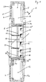
- a tube mill partition 1 is shown schematically in radial section.
- the circular partition rests with its U-shaped fastening ring 2 against the inner wall of the tube mill.
- a diaphragm wall 3 On the upstream, left side according to FIG. 1, a diaphragm wall 3 is provided, which has individual slotted plates 4 in segments. The slotted plates 4 are connected to the fastening ring 2 via sheet metal crosses 24.
- the partition 1 On the downstream right side, the partition 1 is closed off by a rear wall 5 with plates 5a attached to it. Radially inward, the rear wall 5 in the example has a ring equipped with slots 21, the free inside diameter of which roughly corresponds to the free inside diameter of the central part 6 or, according to FIG. 1, the ring 7.
- the essentially circular-cylindrical and tubular middle part 6 forms the central air passage opening, in the central region of which a grille 9 is installed.
- This grid 9, which is preferably made of special steel, has a free passage area of approximately 75% to 90%.
- this grille 9 has a circular inner part 10 which is easily removable and removable, while an outer grille ring 22 is connected to the central part in the usual way.
- Ball deflectors 11 are indicated schematically on both sides of the grille 9, which cause appropriate grinding balls to be ejected into the respective chamber.
- the middle part 6 is equipped to the right of the grille 9 in the region of the rear wall 5 or the rear wall ring 8 with a segmented adjusting ring 15 which has approximately rectangular, segment-like openings 16 in the downstream direction in its edge region.
- the adjusting ring 15 interacts with a stationary ring element 14 which is provided in a form-fitting manner thereon and which likewise has largely identical segment openings 17 in the edge region to the rear wall 5.
- the adjusting ring 15 therefore completely or partially covers the underlying openings 17 of the stationary ring element 14, depending on the angular displacement, in the event of a corresponding shift in the circumferential direction.
- the shredded material passes from the left-hand chamber through the corresponding slots in the diaphragm wall 3 into the lower intermediate region between the diaphragm and rear wall, it is lifted up there by means of appropriate lifting blades 12 and can be adjusted according to the setting of the adjusting ring 15 via the corresponding openings 16 flow through the free inner diameter of the rear wall ring 8 into the chamber provided on the right. A minimal material flow is possible through the slots 21 with the adjusting ring 15 completely closed.
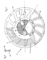
- FIG. 2 shows three different views of the partition wall 1 according to FIG. 1.
- the segment-like division of the slotted wall 3 into individual slotted plates 4, the radial edge area of which has an arcuate shape.
- these slotted plates 4 are followed by a closed, divided ring 7, the free inner diameter of which is adjusted to the degree of filling of the upstream chamber of the tube mill.
- This ring 7 is usually segmented and can therefore be replaced relatively easily.
- the grille with its circular inner part 10 and the outer grille ring 22 is fastened to the central part 6.
- the partition 1 constructed in this way enables a considerably improved passage of air through the partition, so that energy losses are minimized. Due to the segmentation of all essential parts, maintenance work is relatively easy to carry out. In the sense of a modular system, the dividing wall can also be easily adapted to different filling levels of the tube mill with optimal ventilation. The provision of propeller-shaped ball deflectors prevents impairments, in particular of the grille in the air passage area. By the collar is a simple and subsequent installation of such a central part with easy adjustment and large control area for the material flow.
Landscapes
- Engineering & Computer Science (AREA)
- Food Science & Technology (AREA)
- Crushing And Grinding (AREA)
- Cigarettes, Filters, And Manufacturing Of Filters (AREA)
Claims (12)
Applications Claiming Priority (3)
| Application Number | Priority Date | Filing Date | Title |
|---|---|---|---|
| DE3903256A DE3903256A1 (de) | 1989-02-03 | 1989-02-03 | Rohrmuehlen-trennwand |
| DE8901232U DE8901232U1 (de) | 1989-02-03 | 1989-02-03 | Rohrmühlen-Trennwand |
| DE3903256 | 1989-02-03 |
Publications (4)
| Publication Number | Publication Date |
|---|---|
| EP0381084A2 EP0381084A2 (fr) | 1990-08-08 |
| EP0381084A3 EP0381084A3 (en) | 1990-09-26 |
| EP0381084B1 true EP0381084B1 (fr) | 1992-12-09 |
| EP0381084B2 EP0381084B2 (fr) | 1995-11-29 |
Family
ID=39363847
Family Applications (1)
| Application Number | Title | Priority Date | Filing Date |
|---|---|---|---|
| EP90101618A Expired - Lifetime EP0381084B2 (fr) | 1989-02-03 | 1990-01-26 | Paroi de séparation pour broyeur tubulaire |
Country Status (8)
| Country | Link |
|---|---|
| US (1) | US5056722A (fr) |
| EP (1) | EP0381084B2 (fr) |
| JP (1) | JPH0775676B2 (fr) |
| CA (1) | CA2009236C (fr) |
| DE (2) | DE8901232U1 (fr) |
| DK (1) | DK0381084T3 (fr) |
| ES (1) | ES2036849T3 (fr) |
| IT (1) | IT1229454B (fr) |
Families Citing this family (7)
| Publication number | Priority date | Publication date | Assignee | Title |
|---|---|---|---|---|
| CN1043014C (zh) * | 1990-11-13 | 1999-04-21 | 国家建筑材料工业局合肥水泥研究设计院 | 管磨机 |
| DK0665769T3 (da) * | 1992-10-28 | 1997-08-11 | Slegten Sa | Fremgangsmåde og indretning til brug ved rørformede, roterende kuglemøller eller møller med andre lignende formalingsredskaber |
| RU2201288C2 (ru) * | 2000-11-01 | 2003-03-27 | Бикбау Марсель Янович | Устройство для нейтрализации токсичных материалов |
| RU2246355C1 (ru) * | 2003-11-03 | 2005-02-20 | Белгородский государственный технологический университет (БГТУ) им. В.Г. Шухова | Трубная мельница с внутримельничным классифицирующим устройством |
| US20070102550A1 (en) * | 2005-11-07 | 2007-05-10 | Lin Ping H | Plastic grain cutting and transporting mechanism |
| RU2291746C1 (ru) * | 2006-03-16 | 2007-01-20 | Белгородский государственный технологический университет им. В.Г. Шухова (БГТУ им. В.Г. Шухова) | Шаровая барабанная мельница |
| RU209381U1 (ru) * | 2021-11-22 | 2022-03-15 | Общество с ограниченной ответственностью "Объединенная Компания РУСАЛ Инженерно-технологический центр" | Разгрузочная решетка барабанной мельницы |
Family Cites Families (13)
| Publication number | Priority date | Publication date | Assignee | Title |
|---|---|---|---|---|
| US2595509A (en) * | 1946-11-08 | 1952-05-06 | Allan K Brown | Rotary drier and disintegrator |
| DE1507604A1 (de) * | 1966-12-22 | 1969-07-17 | Miag Muehlenbau & Ind Gmbh | UEberfuehrungswand einer Rohrmuehle |
| CA909185A (en) * | 1969-09-04 | 1972-09-05 | Dominion Engineering Works Limited | Autogenous mill system |
| DE2207484C3 (de) * | 1971-02-18 | 1988-07-07 | Slegten, Pierre, Brüssel/Bruxelles | Trennwand in einer Kugelrohrmühle |
| DE2447262C2 (de) * | 1974-10-03 | 1985-05-15 | F.L. Smidth & Co. A/S, Kopenhagen/Koebenhavn | Rohrmühle |
| US3949949A (en) * | 1975-04-25 | 1976-04-13 | Phillips Petroleum Company | Web tension control |
| US4032075A (en) * | 1976-08-16 | 1977-06-28 | Tyer Sr Clarence C | Multi-chambered scrubber having polygonal cross-section |
| BE851835R (fr) * | 1977-02-25 | 1977-06-16 | Slegten Sa | Procede de reglage de la quantite de matiere dans un compartiment de broyage d'un tube broyeur a boulets |
| SU1115799A1 (ru) * | 1983-07-08 | 1984-09-30 | Ивановский Ордена "Знак Почета" Энергетический Институт Им.В.И.Ленина | Барабанна мельница |
| DE3337877A1 (de) * | 1983-10-18 | 1985-04-25 | Krupp Polysius Ag, 4720 Beckum | Rohrmuehle |
| GB8430514D0 (en) * | 1984-12-04 | 1985-01-09 | Smidth & Co As F L | Tube mill |
| DD253948A1 (de) * | 1986-11-28 | 1988-02-10 | Dessau Zementanlagenbau Veb | Reguliereinrichtung fuer zwischen- und austragswaende in rohrmuehlen |
| JPH0646501Y2 (ja) * | 1988-05-21 | 1994-11-30 | 株式会社栗本鐵工所 | チューブミルの流量調整機能を具えた中仕切中心金物 |
-
1989
- 1989-02-03 DE DE8901232U patent/DE8901232U1/de not_active Expired
- 1989-02-03 DE DE3903256A patent/DE3903256A1/de active Granted
- 1989-06-06 IT IT8920797A patent/IT1229454B/it active
-
1990
- 1990-01-26 ES ES199090101618T patent/ES2036849T3/es not_active Expired - Lifetime
- 1990-01-26 DK DK90101618.8T patent/DK0381084T3/da active
- 1990-01-26 EP EP90101618A patent/EP0381084B2/fr not_active Expired - Lifetime
- 1990-01-29 US US07/470,610 patent/US5056722A/en not_active Expired - Fee Related
- 1990-02-02 CA CA002009236A patent/CA2009236C/fr not_active Expired - Lifetime
- 1990-02-03 JP JP2024989A patent/JPH0775676B2/ja not_active Expired - Lifetime
Also Published As
| Publication number | Publication date |
|---|---|
| DE8901232U1 (de) | 1989-03-23 |
| CA2009236A1 (fr) | 1990-08-03 |
| DK0381084T3 (da) | 1993-04-13 |
| IT1229454B (it) | 1991-08-08 |
| EP0381084A3 (en) | 1990-09-26 |
| US5056722A (en) | 1991-10-15 |
| JPH0356151A (ja) | 1991-03-11 |
| EP0381084B2 (fr) | 1995-11-29 |
| DE3903256A1 (de) | 1990-08-09 |
| JPH0775676B2 (ja) | 1995-08-16 |
| CA2009236C (fr) | 1992-04-14 |
| EP0381084A2 (fr) | 1990-08-08 |
| IT8920797A0 (it) | 1989-06-06 |
| ES2036849T3 (es) | 1993-06-01 |
| DE3903256C2 (fr) | 1991-03-28 |
Similar Documents
| Publication | Publication Date | Title |
|---|---|---|
| EP1239966B1 (fr) | Separateur de broyeur | |
| EP1930059B1 (fr) | Pare-goutte | |
| DE202017101442U1 (de) | Sanitäres Einbauteil | |
| EP3102332B1 (fr) | Broyeur à billes à agitateur | |
| EP0381084B1 (fr) | Paroi de séparation pour broyeur tubulaire | |
| DE3736448A1 (de) | Luftdrallauslass und verfahren zu seinem betreiben | |
| EP0676240A1 (fr) | Procédé et dispositif de broyage de matériau avec une granulométrie variable, en particulier broyeur à flux d'air | |
| DE1757161B1 (de) | Prallmuehle | |
| EP0505707B1 (fr) | Ecluse à roue cellulaire | |
| DE3134601C2 (de) | Walzen-Schüsselmühle | |
| DE69508751T2 (de) | Feinmahlanlage mit Hochleistungsabscheider | |
| DE10022536A1 (de) | Mühlensichter | |
| DE1910501A1 (de) | Umluftsichter | |
| EP2659985B1 (fr) | Centrifugeuse à vis a bol plein dotée d'un bord faisant barrage | |
| EP1555068B1 (fr) | Cloison de broyeur tubulaire et méthode de broyage utilisant un tel broyeur | |
| DE19719879B4 (de) | Luftverteilungsvorrichtung | |
| DE19708956A1 (de) | Sichter | |
| DE10044104C2 (de) | Windsichter | |
| EP0641609B1 (fr) | Séparateur pneumatique | |
| DE102017105299A1 (de) | Sanitäres Einbauteil | |
| DE1253562B (de) | Prall- und Schaelmuehle mit mindestens zwei um eine lotrechte Achse umlaufenden Schleuderraedern | |
| DE2808011C2 (fr) | ||
| DE3423412A1 (de) | Vertikalmuehle, insbesondere waelzmuehle fuer kohlenvermahlung | |
| DE3634703C2 (fr) | ||
| DE4219642C1 (de) | Ventilationsanordnung, die ein Gebläse enthält |
Legal Events
| Date | Code | Title | Description |
|---|---|---|---|
| PUAI | Public reference made under article 153(3) epc to a published international application that has entered the european phase |
Free format text: ORIGINAL CODE: 0009012 |
|
| AK | Designated contracting states |
Kind code of ref document: A2 Designated state(s): AT BE CH DE DK ES FR GB GR IT LI LU NL SE |
|
| PUAL | Search report despatched |
Free format text: ORIGINAL CODE: 0009013 |
|
| AK | Designated contracting states |
Kind code of ref document: A3 Designated state(s): AT BE CH DE DK ES FR GB GR IT LI LU NL |
|
| 17P | Request for examination filed |
Effective date: 19900831 |
|
| 17Q | First examination report despatched |
Effective date: 19911016 |
|
| GRAA | (expected) grant |
Free format text: ORIGINAL CODE: 0009210 |
|
| AK | Designated contracting states |
Kind code of ref document: B1 Designated state(s): AT BE CH DE DK ES FR GB GR IT LI LU NL SE |
|
| PG25 | Lapsed in a contracting state [announced via postgrant information from national office to epo] |
Ref country code: SE Effective date: 19921209 Ref country code: NL Free format text: LAPSE BECAUSE OF FAILURE TO SUBMIT A TRANSLATION OF THE DESCRIPTION OR TO PAY THE FEE WITHIN THE PRESCRIBED TIME-LIMIT Effective date: 19921209 Ref country code: GR Free format text: LAPSE BECAUSE OF FAILURE TO SUBMIT A TRANSLATION OF THE DESCRIPTION OR TO PAY THE FEE WITHIN THE PRESCRIBED TIME-LIMIT Effective date: 19921209 Ref country code: GB Effective date: 19921209 Ref country code: FR Effective date: 19921209 |
|
| REF | Corresponds to: |
Ref document number: 83175 Country of ref document: AT Date of ref document: 19921215 Kind code of ref document: T |
|
| REF | Corresponds to: |
Ref document number: 59000556 Country of ref document: DE Date of ref document: 19930121 |
|
| PG25 | Lapsed in a contracting state [announced via postgrant information from national office to epo] |
Ref country code: LU Free format text: LAPSE BECAUSE OF NON-PAYMENT OF DUE FEES Effective date: 19930131 |
|
| ET | Fr: translation filed | ||
| GBT | Gb: translation of ep patent filed (gb section 77(6)(a)/1977) |
Effective date: 19930129 |
|
| ITF | It: translation for a ep patent filed | ||
| REG | Reference to a national code |
Ref country code: DK Ref legal event code: T3 |
|
| REG | Reference to a national code |
Ref country code: ES Ref legal event code: FG2A Ref document number: 2036849 Country of ref document: ES Kind code of ref document: T3 |
|
| PLBI | Opposition filed |
Free format text: ORIGINAL CODE: 0009260 |
|
| 26 | Opposition filed |
Opponent name: KRUPP POLYSIUS AG Effective date: 19930909 |
|
| NLR1 | Nl: opposition has been filed with the epo |
Opponent name: KRUPP POLYSIUS AG |
|
| PGFP | Annual fee paid to national office [announced via postgrant information from national office to epo] |
Ref country code: CH Payment date: 19941221 Year of fee payment: 6 |
|
| PGFP | Annual fee paid to national office [announced via postgrant information from national office to epo] |
Ref country code: AT Payment date: 19941223 Year of fee payment: 6 |
|
| PGFP | Annual fee paid to national office [announced via postgrant information from national office to epo] |
Ref country code: DK Payment date: 19950116 Year of fee payment: 6 |
|
| PGFP | Annual fee paid to national office [announced via postgrant information from national office to epo] |
Ref country code: GB Payment date: 19950117 Year of fee payment: 6 Ref country code: ES Payment date: 19950117 Year of fee payment: 6 |
|
| PGFP | Annual fee paid to national office [announced via postgrant information from national office to epo] |
Ref country code: NL Payment date: 19950131 Year of fee payment: 6 Ref country code: FR Payment date: 19950131 Year of fee payment: 6 |
|
| PUAH | Patent maintained in amended form |
Free format text: ORIGINAL CODE: 0009272 |
|
| STAA | Information on the status of an ep patent application or granted ep patent |
Free format text: STATUS: PATENT MAINTAINED AS AMENDED |
|
| 27A | Patent maintained in amended form |
Effective date: 19951129 |
|
| AK | Designated contracting states |
Kind code of ref document: B2 Designated state(s): AT BE CH DE DK ES FR GB GR IT LI LU NL SE |
|
| REG | Reference to a national code |
Ref country code: CH Ref legal event code: AEN Free format text: AUFRECHTERHALTUNG DES PATENTES IN GEAENDERTER FORM |
|
| PG25 | Lapsed in a contracting state [announced via postgrant information from national office to epo] |
Ref country code: DK Effective date: 19960126 Ref country code: AT Effective date: 19960126 |
|
| REG | Reference to a national code |
Ref country code: DK Ref legal event code: EBP |
|
| PG25 | Lapsed in a contracting state [announced via postgrant information from national office to epo] |
Ref country code: ES Free format text: LAPSE BECAUSE OF NON-PAYMENT OF DUE FEES Effective date: 19960127 |
|
| PG25 | Lapsed in a contracting state [announced via postgrant information from national office to epo] |
Ref country code: LI Effective date: 19960131 Ref country code: CH Effective date: 19960131 |
|
| NLR2 | Nl: decision of opposition | ||
| EN | Fr: translation not filed | ||
| NLV1 | Nl: lapsed or annulled due to failure to fulfill the requirements of art. 29p and 29m of the patents act | ||
| GBV | Gb: ep patent (uk) treated as always having been void in accordance with gb section 77(7)/1977 [no translation filed] |
Effective date: 19921209 |
|
| REG | Reference to a national code |
Ref country code: CH Ref legal event code: PL |
|
| PGFP | Annual fee paid to national office [announced via postgrant information from national office to epo] |
Ref country code: BE Payment date: 19980116 Year of fee payment: 9 |
|
| PGFP | Annual fee paid to national office [announced via postgrant information from national office to epo] |
Ref country code: DE Payment date: 19980130 Year of fee payment: 9 |
|
| PG25 | Lapsed in a contracting state [announced via postgrant information from national office to epo] |
Ref country code: BE Free format text: LAPSE BECAUSE OF NON-PAYMENT OF DUE FEES Effective date: 19990131 |
|
| REG | Reference to a national code |
Ref country code: ES Ref legal event code: FD2A Effective date: 19990503 |
|
| BERE | Be: lapsed |
Owner name: CHRISTIAN PFEIFFER MASCHINENFABRIK G.M.B.H. Effective date: 19990131 |
|
| PG25 | Lapsed in a contracting state [announced via postgrant information from national office to epo] |
Ref country code: DE Free format text: LAPSE BECAUSE OF NON-PAYMENT OF DUE FEES Effective date: 19991103 |
|
| PG25 | Lapsed in a contracting state [announced via postgrant information from national office to epo] |
Ref country code: IT Free format text: LAPSE BECAUSE OF NON-PAYMENT OF DUE FEES Effective date: 20050126 |