EP0381085A1 - Rundballenpresse - Google Patents
Rundballenpresse Download PDFInfo
- Publication number
- EP0381085A1 EP0381085A1 EP90101627A EP90101627A EP0381085A1 EP 0381085 A1 EP0381085 A1 EP 0381085A1 EP 90101627 A EP90101627 A EP 90101627A EP 90101627 A EP90101627 A EP 90101627A EP 0381085 A1 EP0381085 A1 EP 0381085A1
- Authority
- EP
- European Patent Office
- Prior art keywords
- crop
- tines
- crank pins
- crank
- crankshaft
- Prior art date
- Legal status (The legal status is an assumption and is not a legal conclusion. Google has not performed a legal analysis and makes no representation as to the accuracy of the status listed.)
- Granted
Links
Images



Classifications
-
- A—HUMAN NECESSITIES
- A01—AGRICULTURE; FORESTRY; ANIMAL HUSBANDRY; HUNTING; TRAPPING; FISHING
- A01F—PROCESSING OF HARVESTED PRODUCE; HAY OR STRAW PRESSES; DEVICES FOR STORING AGRICULTURAL OR HORTICULTURAL PRODUCE
- A01F15/00—Baling presses for straw, hay or the like
- A01F15/08—Details
- A01F15/10—Feeding devices for the crop material e.g. precompression devices
- A01F15/106—Feeding devices for the crop material e.g. precompression devices for round balers
Definitions
- This invention relates to a machine for forming cylindrical bales of crop having a baling chamber, a pick-up for the crop, and a feeder fork mechanism for receiving the crop from the pick-up and delivering it to the baling chamber, the feeder fork mechanism having: crop supporting strippers arranged side-by-side; and crop advancing tines mounted to move in a cycle in which they extend outwardly between the strippers so as to engage and advance the crop.
- Machines for forming large cylindrical bales of hay (so called "round" balers) are well known.
- the crop is removed from a windrow by a pick-up mechanism and delivered rearwardly to a baling chamber where it is rolled into a bale between sets of oppositely moving belts, the growing bale rotating about a horizontal axis and the baling chamber expanding with the bale.
- the belts are trained over rolls which extend laterally of the machine and most of which are journalled at either end in the sides of the machine.
- a feeder fork mechanism is arranged between the pick-up and the baling chamber in order to advance the crop.
- the feeder fork mechanism has crop supporting strippers, disposed side-by-side in alignment with similar strippers of the pick-up, and crop advancing tines which move in a cycle to extend outwardly between the feeder fork strippers, to push the crop rearwardly toward the baling chamber, and finally to withdraw below the strippers before the cycle starts again.
- the tines are welded on a straight tube which extends transversely below the strippers and which is driven to follow a circular path so that the tines trace out the appropriate pattern of movement just described.
- the present invention overcomes or reduces these difficul wisdomties.
- the feeder mechanism includes a crankshaft with crank pins, and the tines are mounted on the crank pins.
- the shaft is a crankshaft and the tines are mounted on its crank pins, a portion of the crop is advanced as each crank pin carries the tines mounted thereon through the operative crop-engaging part of the tine cycle so build-up of crop is reduced.
- each crank pin has at least three tines thereon.
- crank pins are preferably disposed in substantially the same plane.
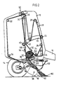
- the machine includes a main frame 10 mounted on a pair of wheels 12, 14.
- the main frame 10 has a pair of upright, opposite, fore-and-aft extending right and left side walls 15, 16 connected by transverse beams.
- a draft tongue 18 is rigid with a cross beam (not shown) at the front of the frame 10 and extends forwardly for attaching the baler to a tractor (not shown) which draws the machine.
- a plurality of lateral rolls extends over the width of the machine.
- One set of rolls 20, 22, 24, 26, 28, 30 is journalled in a forward fixed portion of either side wall, whilst a further set constituted by rolls 32, 34, 36 is journalled in a rearward swingable gate portion 38 of the side walls.
- a belt take-up and tensioning mechanism 66 is provided for this purpose at either side of the machine.
- These mechanisms include: a pair of arms 68, 70 which are mounted on a horizontal transverse pivot shaft 72 at the forward end of the main frame 10; the take-up and tensioning roll 44 which is supported at either end at an intermediate location on the arms 68, 70; and the pair of chamber restricting rolls 40, 42 supported at the free end of the arms.
- the arms 68, 70 are biased in an anti-clockwise direction by a pair of springs one on either side of the main frame 10 of which just the right hand spring 74 is shown and only its arrangement will be described, the other being similar.
- the spring 74 acts through a chain 76, at its lower end, on a bias arm 78 connected rigidly to the pivot shaft 72, the chain 76 being trained over a sprocket 80.
- a further chain 82 similarly connects the spring 74 to one end of a bell crank 84, and the other end of the bell crank bears one end of the take-up and tensioning roll 46.
- the bias arm 78 is also restrained by a piston and cylinder unit 86 pivotally connected at one end to the free end of the bias arm 78 and at the other to the associated right hand side wall 15 of the main frame 10.
- a similar arrangement is provided on the left hand side of the machine so that, for example, the roll 46 is carried by bell cranks on either side.
- the rear gate portion 38 is movable by a pair of upwardly extending hydraulic piston and cylinder units on either side of the main frame 10 of which only a right hand unit 88 is shown which is pivotally connected at its lower end to the forward fixed portion of the side wall 16 and at its upper end to the gate portion 38 which is swingable upwardly and downwardly about a pivot arrangement 90 at its upper forward region.
- the pick-up 60 extends rearwardly and upwardly at a small angle and is conventional in that it has rotating teeth 92 (shown in Figure 3, but omitted from Figure 4 which is highly diagrammatic) which extend between neighbouring strippers 94 and which are mounted on a driven shaft 96 journalled in right and left pick-up plates 98, 100 with crop compressors 102 overhead.
- the feeder fork mechanism 62 is disposed at the rearward downstream end of the pick-up 60, is angled upwardly more steeply, and terminates at the roll 36 at the inlet 58 of the baling chamber 56.
- This mechanism 62 has strippers which are aligned with the pick-up strippers 94.
- Crop advancing tines 106 are arranged to extend between the strippers.
- the tines 106 are rigidly attached in four groups of five 108, 110, 112, 114 to four tubes 116, 118, 120, 122 respectively rotatably received on four crank pins 117, 119, 121, 123 of the crankshaft 124 which is journalled in right and left side plates 126, 128 of the feeder fork mechanism 62.
- four tines or more tines than five can be used in each group.
- fewer or more than four crank pins can be employed each with a group of tines.
- a shaft 130 is disposed below the crankshaft 124 and arms 132, 134, 136, 138 are rotatably mounted on it at intervals along its length corresponding to the tubes 116, 118, 120, 122 and are connected to the respective tubes via arms 140, 142, 144, 146 which at one end are pivotally connected via bushings to the arms 132, 134, 136, 138 and at the other are rigidly attached to the tubes 116, 118, 120, 122.
- the crankshaft 124 is turned, the outer ends of the tines 106 trace out a geometric path 148.
- crank tubes 116, 118, 120, 122 are disposed on a geometric circle 150 at angular intervals one to the next of 90 o .
- a chain 152 from the main drive (not shown) of the machine transmits drive to the crankshaft 124, via a sprocket 154, and in turn drive is transmitted thence, also by a chain and sprocket arrangement 156, to the pick-up shaft 96.
- baling chamber 56 In operation, crop, e.g. straw, lying in a windrow 160 is lifted and conveyed to the baling chamber 56, by the pick-up 60 and feeder fork mechanism 62, where the oppositely moving runs 52, 54 of the belts 48, aided by the stripper roll 20, cause the crop to turn clockwise (as viewed in Figures 1 and 2) to form the bale core 64 which is of increasing size and which eventually overcomes the tension in the belts 48 brought about by the tensioning mechanisms, and the arms 68, 70 consequently swing upwardly and thus the chamber 56 increases in size to accomodate as necessary the bale core 64 as its diameter grows.
- the pick-up 60 and feeder fork mechanism 62 where the oppositely moving runs 52, 54 of the belts 48, aided by the stripper roll 20, cause the crop to turn clockwise (as viewed in Figures 1 and 2) to form the bale core 64 which is of increasing size and which eventually overcomes the tension in the belts 48 brought about by the tensioning
- the feeder fork mechanism 62 receives crop from the pick-up 60 and each group 108, 112, 110, 114 of tines acts in that sequence on the crop to advance it to the inlet 58 of the baling chamber 56. Feeding is, in this way, more uniform than with a conventional feeder fork mechanism with all the tines simply arranged in line on a straight rotating shaft which acts only intermittently on the accumulating crop. Crop is prevented in the present case from accumulating across the width of the inlet 58, and crop advanced by one group of tines 106 may advantageously tend to draw with it also that part of the crop which lies adjacent to it but beyond its ends, although this will depend on the nature of the particular crop involved. Furthermore, the mechanism 62 is better balanced dynamically and has less tendency toward vibration.
- bale core 64 When the bale core 64 reaches the size of the required bale crop flow to the inlet 58 is stopped and the bale is tied with twine and finally discharged by swinging the gate 38 upwardly.
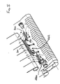
- crankshaft 224 has its crank pins and tubes 216, 218, 220 disposed in substantially the same plane, there being just three such crank pins.
- Outer tubes 216 and 220 (and crank pins) are of equal length whilst middle tube 218 (and crank pin) is twice the length of the tube 216 or 220.
- the tines 206 associated with the tube 218 are at the twelve o'clock position when those on the tubes 216, 220 are at the three o'clock position with the crankshaft 224 moving anti-clockwise when viewed from left of Figure 5.
Landscapes
- Life Sciences & Earth Sciences (AREA)
- Environmental Sciences (AREA)
- Harvester Elements (AREA)
- Apparatuses For Bulk Treatment Of Fruits And Vegetables And Apparatuses For Preparing Feeds (AREA)
- Packaging Of Machine Parts And Wound Products (AREA)
- Pretreatment Of Seeds And Plants (AREA)
- Preliminary Treatment Of Fibers (AREA)
Applications Claiming Priority (2)
| Application Number | Priority Date | Filing Date | Title |
|---|---|---|---|
| GB8901957A GB2228227A (en) | 1989-01-30 | 1989-01-30 | Machine for forming cylindrical bales of crop |
| GB8901957 | 1989-01-30 |
Publications (2)
| Publication Number | Publication Date |
|---|---|
| EP0381085A1 true EP0381085A1 (de) | 1990-08-08 |
| EP0381085B1 EP0381085B1 (de) | 1993-05-26 |
Family
ID=10650814
Family Applications (1)
| Application Number | Title | Priority Date | Filing Date |
|---|---|---|---|
| EP19900101627 Expired - Lifetime EP0381085B1 (de) | 1989-01-30 | 1990-01-27 | Rundballenpresse |
Country Status (4)
| Country | Link |
|---|---|
| EP (1) | EP0381085B1 (de) |
| DE (1) | DE69001681T2 (de) |
| ES (1) | ES2040515T3 (de) |
| GB (1) | GB2228227A (de) |
Cited By (3)
| Publication number | Priority date | Publication date | Assignee | Title |
|---|---|---|---|---|
| EP0619700A4 (de) * | 1991-12-20 | 1995-01-11 | Hay & Forage Ind | Rundballenpresse mit wickelverhinderungsanfangrolle. |
| CN108341105A (zh) * | 2018-02-08 | 2018-07-31 | 中国农业大学 | 一种新型棉花圆捆成型装置 |
| EP3925433A1 (de) * | 2020-06-15 | 2021-12-22 | CNH Industrial Belgium N.V. | Statisch ausgeglichener kurbelbetätigter packermechanismus für eine landwirtschaftliche ballenpresse |
Citations (2)
| Publication number | Priority date | Publication date | Assignee | Title |
|---|---|---|---|---|
| US4198804A (en) * | 1978-08-08 | 1980-04-22 | Gebr. Claas Maschinenfabrik Gmbh | Round baler machine |
| GB2169551A (en) * | 1984-11-30 | 1986-07-16 | Lely Nv C Van Der | Balers |
Family Cites Families (6)
| Publication number | Priority date | Publication date | Assignee | Title |
|---|---|---|---|---|
| FR1260635A (fr) * | 1960-03-28 | 1961-05-12 | Etablissements Rivierre Casali | Perfectionnement aux machines agricoles de récolte, notamment aux pressesramasseuses |
| US3570395A (en) * | 1967-08-31 | 1971-03-16 | Sperry Rand Corp | Baler feeding system |
| US4132163A (en) * | 1976-04-09 | 1979-01-02 | Hesston Corporation | Baler loading method |
| US4106268A (en) * | 1976-11-01 | 1978-08-15 | Hesston Corporation | Method for loading and baling crop material |
| US4275550A (en) * | 1979-10-15 | 1981-06-30 | Hesston Corporation | Crop baler |
| US4525991A (en) * | 1984-01-09 | 1985-07-02 | Sperry Corporation | Baler feeder mechanism |
-
1989
- 1989-01-30 GB GB8901957A patent/GB2228227A/en not_active Withdrawn
-
1990
- 1990-01-27 DE DE1990601681 patent/DE69001681T2/de not_active Expired - Lifetime
- 1990-01-27 ES ES90101627T patent/ES2040515T3/es not_active Expired - Lifetime
- 1990-01-27 EP EP19900101627 patent/EP0381085B1/de not_active Expired - Lifetime
Patent Citations (2)
| Publication number | Priority date | Publication date | Assignee | Title |
|---|---|---|---|---|
| US4198804A (en) * | 1978-08-08 | 1980-04-22 | Gebr. Claas Maschinenfabrik Gmbh | Round baler machine |
| GB2169551A (en) * | 1984-11-30 | 1986-07-16 | Lely Nv C Van Der | Balers |
Cited By (4)
| Publication number | Priority date | Publication date | Assignee | Title |
|---|---|---|---|---|
| EP0619700A4 (de) * | 1991-12-20 | 1995-01-11 | Hay & Forage Ind | Rundballenpresse mit wickelverhinderungsanfangrolle. |
| CN108341105A (zh) * | 2018-02-08 | 2018-07-31 | 中国农业大学 | 一种新型棉花圆捆成型装置 |
| EP3925433A1 (de) * | 2020-06-15 | 2021-12-22 | CNH Industrial Belgium N.V. | Statisch ausgeglichener kurbelbetätigter packermechanismus für eine landwirtschaftliche ballenpresse |
| US11337372B2 (en) | 2020-06-15 | 2022-05-24 | Cnh Industrial America Llc | Statically balanced crank-operated packer mechanism for an agricultural baler |
Also Published As
| Publication number | Publication date |
|---|---|
| DE69001681D1 (de) | 1993-07-01 |
| GB8901957D0 (en) | 1989-03-22 |
| DE69001681T2 (de) | 1993-09-02 |
| ES2040515T3 (es) | 1993-10-16 |
| GB2228227A (en) | 1990-08-22 |
| EP0381085B1 (de) | 1993-05-26 |
Similar Documents
| Publication | Publication Date | Title |
|---|---|---|
| US4581879A (en) | Anti-wrap attachment for rolls of baling machine | |
| US4803832A (en) | Method and apparatus for forming bales | |
| EP0337006B1 (de) | Rundballenpresse | |
| EP0201898B1 (de) | Rundballenpresse | |
| US6651418B1 (en) | Modular pickup, stuffer, and rotor | |
| US6029434A (en) | Down turning stub augers on wide pick-up for round balers | |
| EP0190784B1 (de) | Legemechanismus für Ballenpresse | |
| EP0286776A1 (de) | Aufnahme-Trommel und Rundballenpresse | |
| EP0265583A1 (de) | Rundballenpresse | |
| US2725009A (en) | Tine feeder for hay balers | |
| EP0381068A1 (de) | Rundballenpresse | |
| US4135352A (en) | Semicontinuous large round baling machine | |
| EP0235787B1 (de) | Maschine zur Bildung von Rundballen | |
| EP0381085B1 (de) | Rundballenpresse | |
| EP0087432B1 (de) | Ballenpresse | |
| EP0383076A1 (de) | Rundballenpresse | |
| US4813348A (en) | Machine for forming cylindrical bales of crop | |
| EP0405129B1 (de) | Maschine zum Formen zylindrischer Ballen aus Futterpflanzen | |
| USH1826H (en) | Vertical chamber, open throat round baler having no starter roll | |
| EP0238706A2 (de) | Maschine zur Bildung von Rundballen | |
| EP0169945A1 (de) | Reihenpflanzensammelgerät für Feldhäcksler | |
| EP0097180A4 (de) | Nachrichtensystem mit verteilter steuerung. | |
| GB2195577A (en) | Machine for forming cylindrical bales of crop |
Legal Events
| Date | Code | Title | Description |
|---|---|---|---|
| PUAI | Public reference made under article 153(3) epc to a published international application that has entered the european phase |
Free format text: ORIGINAL CODE: 0009012 |
|
| AK | Designated contracting states |
Kind code of ref document: A1 Designated state(s): DE ES FR GB IT NL |
|
| 17P | Request for examination filed |
Effective date: 19900831 |
|
| 17Q | First examination report despatched |
Effective date: 19910807 |
|
| ITF | It: translation for a ep patent filed | ||
| GRAA | (expected) grant |
Free format text: ORIGINAL CODE: 0009210 |
|
| AK | Designated contracting states |
Kind code of ref document: B1 Designated state(s): DE ES FR GB IT NL |
|
| REF | Corresponds to: |
Ref document number: 69001681 Country of ref document: DE Date of ref document: 19930701 |
|
| ET | Fr: translation filed | ||
| REG | Reference to a national code |
Ref country code: ES Ref legal event code: FG2A Ref document number: 2040515 Country of ref document: ES Kind code of ref document: T3 |
|
| PGFP | Annual fee paid to national office [announced via postgrant information from national office to epo] |
Ref country code: GB Payment date: 19931209 Year of fee payment: 5 |
|
| PG25 | Lapsed in a contracting state [announced via postgrant information from national office to epo] |
Ref country code: ES Free format text: LAPSE BECAUSE OF NON-PAYMENT OF DUE FEES Effective date: 19940128 |
|
| PLBE | No opposition filed within time limit |
Free format text: ORIGINAL CODE: 0009261 |
|
| STAA | Information on the status of an ep patent application or granted ep patent |
Free format text: STATUS: NO OPPOSITION FILED WITHIN TIME LIMIT |
|
| 26N | No opposition filed | ||
| PG25 | Lapsed in a contracting state [announced via postgrant information from national office to epo] |
Ref country code: GB Effective date: 19950127 |
|
| GBPC | Gb: european patent ceased through non-payment of renewal fee |
Effective date: 19950127 |
|
| REG | Reference to a national code |
Ref country code: ES Ref legal event code: FD2A Effective date: 19990405 |
|
| PGFP | Annual fee paid to national office [announced via postgrant information from national office to epo] |
Ref country code: NL Payment date: 20051229 Year of fee payment: 17 |
|
| NLV4 | Nl: lapsed or anulled due to non-payment of the annual fee |
Effective date: 20070801 |
|
| PGFP | Annual fee paid to national office [announced via postgrant information from national office to epo] |
Ref country code: IT Payment date: 20070523 Year of fee payment: 18 |
|
| PG25 | Lapsed in a contracting state [announced via postgrant information from national office to epo] |
Ref country code: NL Free format text: LAPSE BECAUSE OF NON-PAYMENT OF DUE FEES Effective date: 20070801 |
|
| PGFP | Annual fee paid to national office [announced via postgrant information from national office to epo] |
Ref country code: FR Payment date: 20080117 Year of fee payment: 19 |
|
| PGFP | Annual fee paid to national office [announced via postgrant information from national office to epo] |
Ref country code: DE Payment date: 20081222 Year of fee payment: 20 |
|
| PG25 | Lapsed in a contracting state [announced via postgrant information from national office to epo] |
Ref country code: IT Free format text: LAPSE BECAUSE OF NON-PAYMENT OF DUE FEES Effective date: 20080127 |
|
| REG | Reference to a national code |
Ref country code: FR Ref legal event code: ST Effective date: 20091030 |
|
| PG25 | Lapsed in a contracting state [announced via postgrant information from national office to epo] |
Ref country code: FR Free format text: LAPSE BECAUSE OF NON-PAYMENT OF DUE FEES Effective date: 20090202 |
|
| PG25 | Lapsed in a contracting state [announced via postgrant information from national office to epo] |
Ref country code: DE Free format text: LAPSE BECAUSE OF EXPIRATION OF PROTECTION Effective date: 20100127 |