EP0381145A2 - Verfahren und Vorrichtung zur Feststellung von Fehlerstellen in langen metallischen Streifen - Google Patents
Verfahren und Vorrichtung zur Feststellung von Fehlerstellen in langen metallischen Streifen Download PDFInfo
- Publication number
- EP0381145A2 EP0381145A2 EP90101815A EP90101815A EP0381145A2 EP 0381145 A2 EP0381145 A2 EP 0381145A2 EP 90101815 A EP90101815 A EP 90101815A EP 90101815 A EP90101815 A EP 90101815A EP 0381145 A2 EP0381145 A2 EP 0381145A2
- Authority
- EP
- European Patent Office
- Prior art keywords
- metal strip
- elongated metal
- sensor
- surface condition
- transverse position
- Prior art date
- Legal status (The legal status is an assumption and is not a legal conclusion. Google has not performed a legal analysis and makes no representation as to the accuracy of the status listed.)
- Granted
Links
Images
Classifications
-
- G—PHYSICS
- G01—MEASURING; TESTING
- G01N—INVESTIGATING OR ANALYSING MATERIALS BY DETERMINING THEIR CHEMICAL OR PHYSICAL PROPERTIES
- G01N27/00—Investigating or analysing materials by the use of electric, electrochemical, or magnetic means
-
- G—PHYSICS
- G01—MEASURING; TESTING
- G01N—INVESTIGATING OR ANALYSING MATERIALS BY DETERMINING THEIR CHEMICAL OR PHYSICAL PROPERTIES
- G01N27/00—Investigating or analysing materials by the use of electric, electrochemical, or magnetic means
- G01N27/72—Investigating or analysing materials by the use of electric, electrochemical, or magnetic means by investigating magnetic variables
- G01N27/82—Investigating or analysing materials by the use of electric, electrochemical, or magnetic means by investigating magnetic variables for investigating the presence of flaws
- G01N27/90—Investigating or analysing materials by the use of electric, electrochemical, or magnetic means by investigating magnetic variables for investigating the presence of flaws using eddy currents
- G01N27/9013—Arrangements for scanning
- G01N27/9026—Arrangements for scanning by moving the material
-
- G—PHYSICS
- G01—MEASURING; TESTING
- G01N—INVESTIGATING OR ANALYSING MATERIALS BY DETERMINING THEIR CHEMICAL OR PHYSICAL PROPERTIES
- G01N27/00—Investigating or analysing materials by the use of electric, electrochemical, or magnetic means
- G01N27/72—Investigating or analysing materials by the use of electric, electrochemical, or magnetic means by investigating magnetic variables
- G01N27/82—Investigating or analysing materials by the use of electric, electrochemical, or magnetic means by investigating magnetic variables for investigating the presence of flaws
- G01N27/90—Investigating or analysing materials by the use of electric, electrochemical, or magnetic means by investigating magnetic variables for investigating the presence of flaws using eddy currents
- G01N27/9046—Investigating or analysing materials by the use of electric, electrochemical, or magnetic means by investigating magnetic variables for investigating the presence of flaws using eddy currents by analysing electrical signals
Definitions
- the present invention relates generally to a method and apparatus for detecting defect or crack in an elongated metal strip, such as a steel belt. More specifically, the invention relates to a technology for discriminating defect or crack from intersection of two strips which are joined by way of welding.
- crack can be formed during operation of the apparatus. Once cracking occurs on the steel belt, breakage of the belt may subsequently occur to cause damage for associated components. Therefore, it is preferred to detect occurrence of crank in order to know a timing of maintenance of the steel belt.
- the proximity switch generates high frequency magnetic field to induce eddy current on the steel. Magnitude of induced eddy current is variable depending upon the surface condition of the steel. Namely, when crack is formed on the surface of the steel, magnitude of the induced eddy current fluctuates from that induced at the normal surface condition.
- an apparatus for detecting crank on an elongated metal strip employs a plurality of surface condition detecting means operating in synchronism with each other so as to detect the surface conditions of the orientations of the steel belt, which orientations are longitudinally the same position but transversely at different position.
- the apparatus further includes means for deriving a difference of outputs plurality of the surface condition detecting means.
- a discriminator means is also provided in the apparatus for discriminating the surface condition of the strip on the basis of the difference derived by the difference deriving means.
- a defect detecting apparatus comprises: a first sensor placed within a path of an elongated metal strip for monitoring surface condition at a first transverse position of the elongated metal strip to produce a first sensor signal variable of signal level according to the variation of the surface condition at the first transverse position; a second sensor placed within a path of the elongated metal strip for monitoring surface condition at a second transverse position of the elongated metal strip, which second transverse position is so oriented for monitoring transversely off-set position of the elongated metal strip to produce a second sensor signal variable of signal level according to variation of the surface condition at the second transverse position; third means for receiving the first and second sensor signals and deriving an error signal representative of a difference of the first and second sensor signals; and fourth means for comparing the error signal with a predetermined threshold value so that judgement that defect occurs in the elongated metal strip, is made when the error signal level is greater than the threshold value.
- the elongated metal strip may be formed into an endless belt by adjoining both ends, and the adjoining portion of the endless belt extending substantially in transverse with respect to the axis of the path.
- the first and second sensors may comprise proximity switch producing the first and second sensor signals variable of signal levels depending upon variation of resistance at the first and second transverse positions.
- a method for detecting a defect in an elongated strip being transferred through a predetermined path comprises the steps of: providing a first sensor within the path of an elongated metal strip for monitoring surface condition at a first transverse position of the elongated metal strip to produce a first sensor signal variable of signal level according to the variation of the surface condition at the first transverse position; providing a second sensor within a path of the elongated metal strip for monitoring surface condition at a second transverse position of the elongated metal strip, which second transverse position is so oriented for monitoring transversely off-set position of the elongated metal strip to produce a second sensor signal variable of signal level according to variation of the surface condition at the second transverse position; deriving an error signal representative of a difference of the first and second sensor signals; and comparing the error signal with a predetermined threshold value so that judgement that defect occurs in the elongated metal strip, is made when the error signal level is greater than the threshold value.
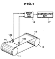
- a belt drive apparatus for which the preferred embodiment of the defect detecting apparatus according to the present invention, is applicable, comprises an endless metal belt 13 extending over a pair of rotary drums 11 and 12 .
- the metal belt 13 may comprises a endless steel belt formed with a flexible steel strip with constant width by joining both ends together by way of welding.
- the welded joining portion 14 of the metal belt 13 extends generally in transverse with respect to the belt transferring axis.
- one of the rotary drums 11 and 12 is connected to an electric motor or other driving power source (not shown) which provides rotational torque for the drum.
- the metal belt 13 is thus driven by the rotational torque applied from the driving power source via one of the rotary drums 11 and 12 .
- a pair of surface sensors 15a and 15b are provided in the vicinity of the belt path through which the metal belt is driven.
- the sensors 15a and 15b are arranged in transverse alignment with respect to the belt transferring axis and in spaced apart relationship with a predetermined distance to each other.
- Each of the sensors 15a and 15b comprises a proximity sensor which is per se well known construction.
- the proximity switch generates high frequency magnetic field for inducing eddy current on the metal belt surface and detects magnitude of current induced on the metal belt surface to produce a sensor signal representative of the detected induced current magnitude. Since the magnitude of the eddy current to be induced on the metal belt surface is variable depending upon the resistance, the signal values of the detector signals output from the sensors 15a and 15b varies according to variation of the resistance in the metal belt 13 .
- the sensors 15a and 15b are connected to an error signal generator 16 .
- the error signal generator 16 receives the sensor signals from both of the sensors 15a and 15b to derive a difference of the signal values.
- the error signal generator 16 thus generates an error signal indicative of the derived difference.
- the error signal generator 16 outputs the error signal to a discriminator circuit 17 .
- the discriminator circuit 17 checks the error signal level against a predetermined threshold level to make judgement that the crank occurs or not depending upon the error signal level.
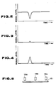
- the signal level of the sensor signal produced by the sensor 1 5a varies as illustrated in Fig. 2 .
- the similar waveform of Fig. 2 may appear when the welded joining portion of the metal belt 13 passes across the sensor 15a . Therefore, it makes discrimination of presence or absence of the crack difficult.
- the welded joining portion 14 can be detected simultaneously by the sensors 15a and 15b so that the essentially identical waveform appears on the sensor signal of the sensor 15b . Therefore, by obtaining the difference of the sensor signals of the sensors 15a and 15b , the signal level of the error signal at the welded joining portion is maintained substantially small, as shown in Fig. 3 .
- the sensor signal level of the sensor 15a or 15b across which the crank containing portion of the belt travels drops substantially.
- the other sensor 15a or 15b does not detect the crack, the sensor signal level is maintained unchanged. In such case, the error signal level becomes substantial as shown in Fig. 4 . Therefore, by utilizing a plurality of sensor and utilizing the difference of the sensor signals, the influence of the welded joining portion of the metal belt can be successfully avoided.
- Fig. 5 shows another embodiment of the defect detecting apparatus according to the present invention.
- three sensors 15a , 15b and 15c are employed in spaced apart relationship with a predetermined distance and aligned transversely with respect to the axis of belt travel.
- two error signals are derived on the basis of the sensor signals of the sensors 15a and 15b and 15b and 15c . Based on the error signals thus derived, discrimination whether the defect, e.g. crack, is present or absent can be performed effectively and in more precise manner.
Landscapes
- Chemical & Material Sciences (AREA)
- Chemical Kinetics & Catalysis (AREA)
- Electrochemistry (AREA)
- Physics & Mathematics (AREA)
- Health & Medical Sciences (AREA)
- Life Sciences & Earth Sciences (AREA)
- Analytical Chemistry (AREA)
- Biochemistry (AREA)
- General Health & Medical Sciences (AREA)
- General Physics & Mathematics (AREA)
- Immunology (AREA)
- Pathology (AREA)
- Investigating Or Analyzing Materials By The Use Of Magnetic Means (AREA)
- Investigating Or Analyzing Materials By The Use Of Electric Means (AREA)
Applications Claiming Priority (2)
| Application Number | Priority Date | Filing Date | Title |
|---|---|---|---|
| JP10310/89U | 1989-01-30 | ||
| JP1989010310U JPH089641Y2 (ja) | 1989-01-30 | 1989-01-30 | スチールベルトのクラック検出装置 |
Publications (3)
| Publication Number | Publication Date |
|---|---|
| EP0381145A2 true EP0381145A2 (de) | 1990-08-08 |
| EP0381145A3 EP0381145A3 (en) | 1990-10-17 |
| EP0381145B1 EP0381145B1 (de) | 1994-09-21 |
Family
ID=11746672
Family Applications (1)
| Application Number | Title | Priority Date | Filing Date |
|---|---|---|---|
| EP90101815A Expired - Lifetime EP0381145B1 (de) | 1989-01-30 | 1990-01-30 | Verfahren und Vorrichtung zur Feststellung von Fehlerstellen in langen metallischen Streifen |
Country Status (5)
| Country | Link |
|---|---|
| US (1) | US5146163A (de) |
| EP (1) | EP0381145B1 (de) |
| JP (1) | JPH089641Y2 (de) |
| KR (1) | KR970000282Y1 (de) |
| DE (1) | DE69012598T2 (de) |
Cited By (2)
| Publication number | Priority date | Publication date | Assignee | Title |
|---|---|---|---|---|
| WO2009138551A1 (en) * | 2008-05-14 | 2009-11-19 | Metso Paper, Inc. | Method and device arrangement for controlling the quality of a metal belt |
| CN116465735A (zh) * | 2023-04-12 | 2023-07-21 | 首钢京唐钢铁联合有限责任公司 | 检测罩式退火卷粘结缺陷的方法和装置 |
Families Citing this family (9)
| Publication number | Priority date | Publication date | Assignee | Title |
|---|---|---|---|---|
| WO1992014145A1 (en) * | 1991-02-04 | 1992-08-20 | Nkk Corporation | Magnetic inspecting method and device therefor |
| US5426362A (en) * | 1992-09-30 | 1995-06-20 | Ninnis; Ronald M. | Damage detection apparatus and method for a conveyor belt having magnetically permeable members |
| US5512835A (en) * | 1992-12-22 | 1996-04-30 | Hughes Aircraft Company | Electrical probe and method for measuring gaps and other discontinuities in enclosures using electrical inductance for RF shielding assessment |
| US5463201A (en) * | 1993-02-04 | 1995-10-31 | Generla Electric Company | Seam-tracking apparatus for a welding system employing an array of eddy current elements |
| US6727691B2 (en) * | 2000-06-26 | 2004-04-27 | Jentek Sensors, Inc. | High resolution inductive sensor arrays for material and defect characterization of welds |
| DE102004044335A1 (de) * | 2004-09-09 | 2006-04-06 | Robert Bosch Gmbh | Verfahren zum Überwachen von redundanten Sensorsignalen |
| JP4961816B2 (ja) * | 2006-04-18 | 2012-06-27 | 富士ゼロックス株式会社 | ベルト定着装置及びこれを用いた画像形成装置 |
| CN105675713B (zh) * | 2016-04-06 | 2018-08-07 | 山西慧达澳星科技有限公司 | 一种电梯曳引钢带无损检测装置及方法 |
| CN107719790B (zh) * | 2017-10-20 | 2019-08-20 | 超威电源有限公司 | 一种打包带偏斜度在线自动检测装置 |
Family Cites Families (12)
| Publication number | Priority date | Publication date | Assignee | Title |
|---|---|---|---|---|
| US2746012A (en) * | 1952-04-17 | 1956-05-15 | Tuboscope Company | Inductive electromagnetic inspection |
| US2939963A (en) * | 1956-05-18 | 1960-06-07 | Ralph R Wegner | Photoelectric inspection apparatus |
| GB1005816A (en) * | 1960-10-14 | 1965-09-29 | Gkn Group Services Ltd | Improvements relating to methods of and apparatus for the detection of flaws |
| US3141952A (en) * | 1961-02-01 | 1964-07-21 | United Aircraft Corp | Electronic seam follower |
| US3247453A (en) * | 1961-03-09 | 1966-04-19 | Api Instr Company | Magnetic flaw detector with exciting and sensing coils axially aligned on opposite sides of the material |
| US3409779A (en) * | 1965-11-02 | 1968-11-05 | Appalachian Electronic Instr | Hole detector having logic circuitry for seam skipping |
| SE301731B (de) * | 1966-02-24 | 1968-06-17 | Essem Metotest Ab | |
| US3469182A (en) * | 1967-06-23 | 1969-09-23 | Gkn Group Services Ltd | Flaw detecting apparatus with mechanical scanning of detection means |
| JPS52127289A (en) * | 1976-04-16 | 1977-10-25 | Bando Chemical Ind | Device for detecting longitudinal split in conveyer belt |
| PL142267B1 (en) * | 1983-12-30 | 1987-10-31 | Akad Gorniczo Hutnicza | Apparatus for magnetically testing conveyor belts |
| JPS63138259A (ja) * | 1986-12-01 | 1988-06-10 | Nkk Corp | 磁気探査法 |
| US4808924A (en) * | 1987-02-19 | 1989-02-28 | Atomic Energy Of Canada Limited | Circumferentially compensating eddy current probe with alternately polarized transmit coils and receiver coils |
-
1989
- 1989-01-30 JP JP1989010310U patent/JPH089641Y2/ja not_active Expired - Lifetime
-
1990
- 1990-01-29 US US07/471,372 patent/US5146163A/en not_active Expired - Lifetime
- 1990-01-30 EP EP90101815A patent/EP0381145B1/de not_active Expired - Lifetime
- 1990-01-30 DE DE69012598T patent/DE69012598T2/de not_active Expired - Fee Related
- 1990-01-30 KR KR2019900000970U patent/KR970000282Y1/ko not_active Expired - Fee Related
Cited By (2)
| Publication number | Priority date | Publication date | Assignee | Title |
|---|---|---|---|---|
| WO2009138551A1 (en) * | 2008-05-14 | 2009-11-19 | Metso Paper, Inc. | Method and device arrangement for controlling the quality of a metal belt |
| CN116465735A (zh) * | 2023-04-12 | 2023-07-21 | 首钢京唐钢铁联合有限责任公司 | 检测罩式退火卷粘结缺陷的方法和装置 |
Also Published As
| Publication number | Publication date |
|---|---|
| KR900014808U (ko) | 1990-08-02 |
| KR970000282Y1 (ko) | 1997-01-13 |
| DE69012598T2 (de) | 1995-01-19 |
| EP0381145B1 (de) | 1994-09-21 |
| US5146163A (en) | 1992-09-08 |
| JPH02101256U (de) | 1990-08-13 |
| EP0381145A3 (en) | 1990-10-17 |
| DE69012598D1 (de) | 1994-10-27 |
| JPH089641Y2 (ja) | 1996-03-21 |
Similar Documents
| Publication | Publication Date | Title |
|---|---|---|
| US5146163A (en) | Method and apparatus having transversely offset eddy current sensors for detecting defect in elongated metal strip joined by way of welding | |
| US4409852A (en) | Method of measuring stretch of conveyor belt | |
| EP0274691B1 (de) | Fehlerdiagnosesystem für eine Rotorwicklung einer elektrischen Drehfeldmaschine | |
| EP0214046A2 (de) | Verfahren und System zum Lokalisieren und Prüfen einer Laschennat in einem längsgeschweissten Metallrohr | |
| US5327353A (en) | Method of detecting state of cutting rubber sheet having parallel cords embedded therein | |
| CA2115104C (en) | Railway vehicle wheel detector utilizing magnetic differential bridge | |
| US6569046B1 (en) | Belt wear detection system and method | |
| EP0277467A1 (de) | Verfahren und Vorrichtung zum zerstörungsfreien Prüfen von durch elektrisches Schweissen hergestellten Schweisspunkten zwischen Metallblechen | |
| US20170363688A1 (en) | System and method for inspection of a generator stator core step iron region with the rotor in-situ | |
| JP2003518629A (ja) | 信号発生器での誤接続の識別方法および装置 | |
| JPH0648549A (ja) | コンベヤベルトの縦裂き検出装置 | |
| KR100298597B1 (ko) | 원료이송용컨베이어벨트상의금속편검출방법및그의장치 | |
| EP0241013B1 (de) | Vorrichtung zur Feststellung von Oberflächenmikrofehlern in einem Metallwerkstück | |
| CA1242504A (en) | Device for the detection of longitudinal cracking in conveyor belt | |
| EP0057512B1 (de) | Vorrichtung zur Orientierung von Behältern | |
| KR100270098B1 (ko) | 용접품질 판정장치 및 방법 | |
| JPH0781821B2 (ja) | 継目検出方法 | |
| Harrison | Testing steel-cord belt splices with a magnetic conveyor belt monitor | |
| JPH10170481A (ja) | 渦流探傷装置 | |
| JP3516884B2 (ja) | トロリ線のろう付け部の劣化判定装置 | |
| JP2000230924A (ja) | エッジ割れ検出方法及びこれを用いたエッジ割れ検出装置 | |
| JP3299911B2 (ja) | 乗客コンベア用ハンドレール接続部の異常判定方法 | |
| SU1564510A1 (ru) | Устройство дл обнаружени нарушений масл ной пленки по бортам и поверхност м качени в роликовом подшипнике | |
| JPS6449708A (en) | Abnormality diagnosing device for rolling bearing | |
| KR20030053806A (ko) | 벨트 내부의 스틸코드 파선검출장치 및 그 검출방법 |
Legal Events
| Date | Code | Title | Description |
|---|---|---|---|
| PUAI | Public reference made under article 153(3) epc to a published international application that has entered the european phase |
Free format text: ORIGINAL CODE: 0009012 |
|
| AK | Designated contracting states |
Kind code of ref document: A2 Designated state(s): DE FR GB IT |
|
| PUAL | Search report despatched |
Free format text: ORIGINAL CODE: 0009013 |
|
| RHK1 | Main classification (correction) |
Ipc: G01N 27/82 |
|
| AK | Designated contracting states |
Kind code of ref document: A3 Designated state(s): DE FR GB IT |
|
| 17P | Request for examination filed |
Effective date: 19901219 |
|
| 17Q | First examination report despatched |
Effective date: 19920624 |
|
| GRAA | (expected) grant |
Free format text: ORIGINAL CODE: 0009210 |
|
| AK | Designated contracting states |
Kind code of ref document: B1 Designated state(s): DE FR GB IT |
|
| REF | Corresponds to: |
Ref document number: 69012598 Country of ref document: DE Date of ref document: 19941027 |
|
| ITF | It: translation for a ep patent filed | ||
| ET | Fr: translation filed | ||
| PLBE | No opposition filed within time limit |
Free format text: ORIGINAL CODE: 0009261 |
|
| STAA | Information on the status of an ep patent application or granted ep patent |
Free format text: STATUS: NO OPPOSITION FILED WITHIN TIME LIMIT |
|
| 26N | No opposition filed | ||
| PGFP | Annual fee paid to national office [announced via postgrant information from national office to epo] |
Ref country code: FR Payment date: 19961216 Year of fee payment: 8 |
|
| PGFP | Annual fee paid to national office [announced via postgrant information from national office to epo] |
Ref country code: GB Payment date: 19970113 Year of fee payment: 8 |
|
| PGFP | Annual fee paid to national office [announced via postgrant information from national office to epo] |
Ref country code: DE Payment date: 19970310 Year of fee payment: 8 |
|
| PG25 | Lapsed in a contracting state [announced via postgrant information from national office to epo] |
Ref country code: GB Free format text: LAPSE BECAUSE OF NON-PAYMENT OF DUE FEES Effective date: 19980130 |
|
| PG25 | Lapsed in a contracting state [announced via postgrant information from national office to epo] |
Ref country code: FR Free format text: THE PATENT HAS BEEN ANNULLED BY A DECISION OF A NATIONAL AUTHORITY Effective date: 19980131 |
|
| GBPC | Gb: european patent ceased through non-payment of renewal fee |
Effective date: 19980130 |
|
| PG25 | Lapsed in a contracting state [announced via postgrant information from national office to epo] |
Ref country code: DE Free format text: LAPSE BECAUSE OF NON-PAYMENT OF DUE FEES Effective date: 19981001 |
|
| REG | Reference to a national code |
Ref country code: FR Ref legal event code: ST |
|
| PG25 | Lapsed in a contracting state [announced via postgrant information from national office to epo] |
Ref country code: IT Free format text: LAPSE BECAUSE OF NON-PAYMENT OF DUE FEES Effective date: 20050130 |