EP0381285A2 - Meng- und Abgabevorrichtung von Wasser bei konstanter Temperatur - Google Patents
Meng- und Abgabevorrichtung von Wasser bei konstanter Temperatur Download PDFInfo
- Publication number
- EP0381285A2 EP0381285A2 EP90200201A EP90200201A EP0381285A2 EP 0381285 A2 EP0381285 A2 EP 0381285A2 EP 90200201 A EP90200201 A EP 90200201A EP 90200201 A EP90200201 A EP 90200201A EP 0381285 A2 EP0381285 A2 EP 0381285A2
- Authority
- EP
- European Patent Office
- Prior art keywords
- fact
- mixer
- mixing
- systems
- water
- Prior art date
- Legal status (The legal status is an assumption and is not a legal conclusion. Google has not performed a legal analysis and makes no representation as to the accuracy of the status listed.)
- Withdrawn
Links
Images


Classifications
-
- F—MECHANICAL ENGINEERING; LIGHTING; HEATING; WEAPONS; BLASTING
- F16—ENGINEERING ELEMENTS AND UNITS; GENERAL MEASURES FOR PRODUCING AND MAINTAINING EFFECTIVE FUNCTIONING OF MACHINES OR INSTALLATIONS; THERMAL INSULATION IN GENERAL
- F16K—VALVES; TAPS; COCKS; ACTUATING-FLOATS; DEVICES FOR VENTING OR AERATING
- F16K11/00—Multiple-way valves, e.g. mixing valves; Pipe fittings incorporating such valves
- F16K11/10—Multiple-way valves, e.g. mixing valves; Pipe fittings incorporating such valves with two or more closure members not moving as a unit
- F16K11/20—Multiple-way valves, e.g. mixing valves; Pipe fittings incorporating such valves with two or more closure members not moving as a unit operated by separate actuating members
-
- E—FIXED CONSTRUCTIONS
- E03—WATER SUPPLY; SEWERAGE
- E03C—DOMESTIC PLUMBING INSTALLATIONS FOR FRESH WATER OR WASTE WATER; SINKS
- E03C1/00—Domestic plumbing installations for fresh water or waste water; Sinks
- E03C1/02—Plumbing installations for fresh water
- E03C1/05—Arrangements of devices on wash-basins, baths, sinks, or the like for remote control of taps
-
- F—MECHANICAL ENGINEERING; LIGHTING; HEATING; WEAPONS; BLASTING
- F16—ENGINEERING ELEMENTS AND UNITS; GENERAL MEASURES FOR PRODUCING AND MAINTAINING EFFECTIVE FUNCTIONING OF MACHINES OR INSTALLATIONS; THERMAL INSULATION IN GENERAL
- F16K—VALVES; TAPS; COCKS; ACTUATING-FLOATS; DEVICES FOR VENTING OR AERATING
- F16K11/00—Multiple-way valves, e.g. mixing valves; Pipe fittings incorporating such valves
- F16K11/02—Multiple-way valves, e.g. mixing valves; Pipe fittings incorporating such valves with all movable sealing faces moving as one unit
- F16K11/06—Multiple-way valves, e.g. mixing valves; Pipe fittings incorporating such valves with all movable sealing faces moving as one unit comprising only sliding valves, i.e. sliding closure elements
- F16K11/072—Multiple-way valves, e.g. mixing valves; Pipe fittings incorporating such valves with all movable sealing faces moving as one unit comprising only sliding valves, i.e. sliding closure elements with pivoted closure members
- F16K11/074—Multiple-way valves, e.g. mixing valves; Pipe fittings incorporating such valves with all movable sealing faces moving as one unit comprising only sliding valves, i.e. sliding closure elements with pivoted closure members with flat sealing faces
- F16K11/0746—Multiple-way valves, e.g. mixing valves; Pipe fittings incorporating such valves with all movable sealing faces moving as one unit comprising only sliding valves, i.e. sliding closure elements with pivoted closure members with flat sealing faces with two or more closure plates comprising a single lever control
Definitions
- the scope of this invention is to obviate the above-mentioned problem by providing a device for mixing and dispensing water at a constant temperature under the most widely varied conditions.
- This scope is achieved by providing a device for mixing hot and cold water from two supply systems, and dispensing water on command at a temperature established by the mixing ratio, characterized by the fact of comprising in combination: a mixing element connected to a first electric ratiomotor for varying the mixing ratio of the latter; a regulating element for controlling the flow of water from said mixer, operatively connected to a second electric ratiomotor; a compensator for correcting the difference in pressure in the two systems connected between said systems and said mixing element, said compensator acting, in proportion to such difference, on flow apertures between said systems and said mixer in order to reduce the area of flow from the system with a higher pressure and increase the area of flow from the system with a lower pressure.
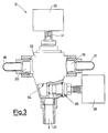
- an electromechanical regulating unit comprises a pressure compensating element 11 having inlets 13 and 14 connected, respectively, to a hot water supply system and to a cold water supply system, neither of which is shown since they can be of any known type.
- the compensator 11 has outlets 15 and 16 connected, by means of pipes 17 and 18, to the respective inlets 19 and 20 of a regulating element 12 with an outlet 21.
- the inlets 13 and 14 communicate with a chamber 22 divided into two halves by a flexible diaphragm 23 which keeps the two flows separate and which axially supports a plug member 24 symmetrical with respect to the surface of the latter and sliding tightly on two outlet elements 25 and 26 so as to achieve, with the holes 28 and 29, variable sectional areas of flow.
- the communication between each half-chamber and its respective flow aperture is made possible by holes 30 and 31 in the plug member.
- the inlet 13 thus communicates with its corresponding outlet 15 through, in sequence, a half-chamber of the chamber 22, the hole 30, the free apertures of the holes 28 and the element 25.
- the inlet 14 communicates with its corresponding outlet 16 through in sequence the other half-chamber, the hole 31, the free apertures of the holes 29 and the element 26.
- the regulating element 12 comprises a thermostatic mixer 32 (for example, of the type with a thermostatic cartridge), of known type, for mixing water coming from the inlets 19 and 20, with a mixing ratio determined by the angular position of a control pin 41 set by a ratiomotor 33.
- the aforesaid mixer will not be further described since it is easily imaginable by anyone expert in the field.
- a flow control device 35 operated by means of a second electric ratiomotor 36 is disposed between the outlet 34 of the mixer and the outlet duct 21 of the regulating unit.
- the device 35 can be of any known type easily imaginable by the technician; for example, it can be of the screw type with ceramic disks.
- the ratiomotors 33 and 36 are operatively connected to a monitoring device 37 controlled by means of a control panel 38.
- the monitoring device can be made using known means, for example, a microprocessor, as is easiy imaginable by the technician, especially in the light of the following operating description.
- control panel has a first pair of pushbuttons marked “+” and “-” for controlling the rotation of the motor 33 and a second pair of pushbuttons marked “+” and “-” for controlling the rotation of the motor 36. It is also provided with a "start/stop” pushbutton for activating and deactivating the entire device.
- two optical indicators 39, 40 (for example, of the liquid crystal type) indirectly display the temperature and flow rate of the water discharged from the duct 21, respectively, as will be illustrated further on.
- the outlet 21 of the device is connected for example to the water tap of a washbasin, bath tub, or other sanitary fitting and with the control panel 38 close to it.
- the regulating unit described above operates in the following way.
- the diaphragm 23 has both faces subjected to the pressures of the incoming flows of water from the pipes 13 and 14. In particular, if the pressure difference between the faces is nil, the diaphragm is in the flat disposition shown in figure 2 and the sliding plug member 24 consequently keeps the apertures determined by its sliding ends and by the corresponding holes 28 and 29 open by the same degree.
- the corresponding flexure of the diaphragm in the direction of the lower pressure shifts the plug member 24 which narrows the apertures on the higher pressure side and widens the apertures on the lower pressure side.
- the two flows of water reach the mixer and are mixed together in the proportions established by the angular position of the control pin of the mixer, which in practice determines the temperature of the mixed water flowing from the duct 21, the flow rate of which is determined by the device 35.
- the device 35 In the inoperative position, the device 35 is competely closed.
- the control system When the "start/stop" pushbutton is pressed the control system is activated and it is thus possible to manually regulate the flow rate and the temperature of the water flowing from the duct 21 by pressing the corresponding pairs of pushbuttons "+" and "-” for controlling the motors.
- the user may, for example memorize the flow rate and delivery temperature conditions that he considers the most suitable by means of the and "-" pushbuttons and subsequently press only the "start/stop” pushbutton in order to turn the water on or off.
- a regulating device carried out according to the innovatory principles herein claimed supplies a very accurate temperature control stabilizing in the short term the mixing ratio by the compensator 11, and regulating in the long term said ratio by the well known thermostatic characteristic of the mixer which, due to its inertia in responding, is ineffectual in controlling the rapid temperature changes while it is fit for the slow changes.
- a single mixing unit can be used for several outlet taps even of different types of sanitary fittings, by providing on-off means of the known type (for example, solenoid valves) between said outlets and said unit, so as to be able to simultaneously regulate the temperature and, if necessary, the flow rate of the water flowing from all the connected taps.
- on-off means of the known type for example, solenoid valves
- the mixer 32 can be made without thermostatic characteristics. Conversely, these characteristics can be easily obtained electronically, by controlling the motor 33 with a signal which takes account of the operation of the "+" and "-" pushbuttons and also of the indication of a temperature sensor disposed on the route of the mixed water, as is easily imaginable by any expert technician.
Landscapes
- Engineering & Computer Science (AREA)
- General Engineering & Computer Science (AREA)
- Mechanical Engineering (AREA)
- Health & Medical Sciences (AREA)
- Life Sciences & Earth Sciences (AREA)
- Hydrology & Water Resources (AREA)
- Public Health (AREA)
- Water Supply & Treatment (AREA)
- Control Of Temperature (AREA)
- Domestic Hot-Water Supply Systems And Details Of Heating Systems (AREA)
Applications Claiming Priority (2)
| Application Number | Priority Date | Filing Date | Title |
|---|---|---|---|
| IT8919291A IT1228179B (it) | 1989-02-02 | 1989-02-02 | Dispositivo per miscelazione ed erogazione a temperatura costante di acqua. |
| IT1929189 | 1989-02-02 |
Publications (2)
| Publication Number | Publication Date |
|---|---|
| EP0381285A2 true EP0381285A2 (de) | 1990-08-08 |
| EP0381285A3 EP0381285A3 (de) | 1991-04-24 |
Family
ID=11156473
Family Applications (1)
| Application Number | Title | Priority Date | Filing Date |
|---|---|---|---|
| EP19900200201 Withdrawn EP0381285A3 (de) | 1989-02-02 | 1990-01-29 | Meng- und Abgabevorrichtung von Wasser bei konstanter Temperatur |
Country Status (2)
| Country | Link |
|---|---|
| EP (1) | EP0381285A3 (de) |
| IT (1) | IT1228179B (de) |
Cited By (7)
| Publication number | Priority date | Publication date | Assignee | Title |
|---|---|---|---|---|
| EP0753118A4 (de) * | 1995-01-10 | 1998-01-07 | Masco Corp | Druckausgleichvorrichtung |
| EP0886013A1 (de) * | 1997-06-19 | 1998-12-23 | Emhart Inc. | Verbrühsicheres Wasserhahnsystem |
| GB2469435A (en) * | 2009-01-30 | 2010-10-20 | Touchtile Ltd | A Fluid Regulation device |
| EP2123954A3 (de) * | 2008-05-20 | 2014-03-26 | Behr Thermot-tronik Italia S.P.A. | Hahn- / Mischeinheit für Wassersysteme |
| CN106224596A (zh) * | 2016-08-31 | 2016-12-14 | 黄玉 | 一种控温水龙头 |
| CN106641422A (zh) * | 2015-10-29 | 2017-05-10 | 珠海三威注塑模具有限公司 | 一种智能水龙头温度控制装置 |
| CN107940023A (zh) * | 2017-11-22 | 2018-04-20 | 解钟敏 | 自动水温调节混水阀装置 |
Family Cites Families (2)
| Publication number | Priority date | Publication date | Assignee | Title |
|---|---|---|---|---|
| FR2506886A1 (fr) * | 1981-05-27 | 1982-12-03 | Chantoiseau Sa Robinetterie | Robinet mitigeur d'eau |
| KR890001016B1 (ko) * | 1984-12-11 | 1989-04-18 | 마쯔시다덴기산교 가부시기가이샤 | 탕수혼합장치 |
-
1989
- 1989-02-02 IT IT8919291A patent/IT1228179B/it active
-
1990
- 1990-01-29 EP EP19900200201 patent/EP0381285A3/de not_active Withdrawn
Cited By (7)
| Publication number | Priority date | Publication date | Assignee | Title |
|---|---|---|---|---|
| EP0753118A4 (de) * | 1995-01-10 | 1998-01-07 | Masco Corp | Druckausgleichvorrichtung |
| EP0886013A1 (de) * | 1997-06-19 | 1998-12-23 | Emhart Inc. | Verbrühsicheres Wasserhahnsystem |
| EP2123954A3 (de) * | 2008-05-20 | 2014-03-26 | Behr Thermot-tronik Italia S.P.A. | Hahn- / Mischeinheit für Wassersysteme |
| GB2469435A (en) * | 2009-01-30 | 2010-10-20 | Touchtile Ltd | A Fluid Regulation device |
| CN106641422A (zh) * | 2015-10-29 | 2017-05-10 | 珠海三威注塑模具有限公司 | 一种智能水龙头温度控制装置 |
| CN106224596A (zh) * | 2016-08-31 | 2016-12-14 | 黄玉 | 一种控温水龙头 |
| CN107940023A (zh) * | 2017-11-22 | 2018-04-20 | 解钟敏 | 自动水温调节混水阀装置 |
Also Published As
| Publication number | Publication date |
|---|---|
| IT1228179B (it) | 1991-06-04 |
| IT8919291A0 (it) | 1989-02-02 |
| EP0381285A3 (de) | 1991-04-24 |
Similar Documents
| Publication | Publication Date | Title |
|---|---|---|
| US6446875B1 (en) | Water temperature and pressure control system | |
| KR0183333B1 (ko) | 자동배수용 위생수전 | |
| US5979776A (en) | Water flow and temperature controller for a bathtub faucet | |
| DE69202995T2 (de) | Wasserspender mit einem durch einen kleinen Motor angetriebenen rotierenden Kopf. | |
| PL181009B1 (pl) | Zawór mieszający termostatyczny do kranu | |
| EP0381285A2 (de) | Meng- und Abgabevorrichtung von Wasser bei konstanter Temperatur | |
| US7040542B2 (en) | Method and appliance for regulating the inflow of hot water to a container | |
| US20080078785A1 (en) | Dispensing measuring device | |
| US4164239A (en) | Hot and cold water ratio and volume manual device | |
| US3965937A (en) | Washbasin faucet installation with auxiliary fitting for mouth spray or similar apparatus | |
| US5348223A (en) | Method and apparatus for controlling temperature of a liquid | |
| JPS61116187A (ja) | バスシヤワ−装置 | |
| CA1253935A (en) | Method and apparatus for controlling temperature of a liquid | |
| JP2623545B2 (ja) | 給湯装置 | |
| EP0227916B1 (de) | Elektronische Wassermischungsvorrichtung | |
| US4463899A (en) | Relating to shower fittings | |
| JPS6352218A (ja) | 出湯制御装置 | |
| JP2583863B2 (ja) | 給湯装置 | |
| JP2523548B2 (ja) | 給湯装置 | |
| JP2663432B2 (ja) | 給湯装置 | |
| JP2566234Y2 (ja) | 自動給水装置 | |
| JPH0271026A (ja) | 自動給湯装置 | |
| JPS62282308A (ja) | 湯水混合制御装置 | |
| JP2796090B2 (ja) | 給湯装置 | |
| JP2565576Y2 (ja) | シャワー装置 |
Legal Events
| Date | Code | Title | Description |
|---|---|---|---|
| PUAI | Public reference made under article 153(3) epc to a published international application that has entered the european phase |
Free format text: ORIGINAL CODE: 0009012 |
|
| AK | Designated contracting states |
Kind code of ref document: A2 Designated state(s): AT BE CH DE ES FR GB GR IT LI LU NL SE |
|
| PUAL | Search report despatched |
Free format text: ORIGINAL CODE: 0009013 |
|
| AK | Designated contracting states |
Kind code of ref document: A3 Designated state(s): AT BE CH DE ES FR GB GR IT LI LU NL SE |
|
| 17P | Request for examination filed |
Effective date: 19910925 |
|
| 17Q | First examination report despatched |
Effective date: 19930119 |
|
| STAA | Information on the status of an ep patent application or granted ep patent |
Free format text: STATUS: THE APPLICATION HAS BEEN WITHDRAWN |
|
| 18W | Application withdrawn |
Withdrawal date: 19930422 |