EP0381599A2 - Steuerungssystem für Roboter-Fertigungszellen mit verbessertem Ein/Ausgangsinterface für bessere Fertigungszellenfunktion - Google Patents
Steuerungssystem für Roboter-Fertigungszellen mit verbessertem Ein/Ausgangsinterface für bessere Fertigungszellenfunktion Download PDFInfo
- Publication number
- EP0381599A2 EP0381599A2 EP90420045A EP90420045A EP0381599A2 EP 0381599 A2 EP0381599 A2 EP 0381599A2 EP 90420045 A EP90420045 A EP 90420045A EP 90420045 A EP90420045 A EP 90420045A EP 0381599 A2 EP0381599 A2 EP 0381599A2
- Authority
- EP
- European Patent Office
- Prior art keywords
- workcell
- input
- control
- robot
- output
- Prior art date
- Legal status (The legal status is an assumption and is not a legal conclusion. Google has not performed a legal analysis and makes no representation as to the accuracy of the status listed.)
- Withdrawn
Links
Images





Classifications
-
- G—PHYSICS
- G05—CONTROLLING; REGULATING
- G05B—CONTROL OR REGULATING SYSTEMS IN GENERAL; FUNCTIONAL ELEMENTS OF SUCH SYSTEMS; MONITORING OR TESTING ARRANGEMENTS FOR SUCH SYSTEMS OR ELEMENTS
- G05B19/00—Program-control systems
- G05B19/02—Program-control systems electric
- G05B19/418—Total factory control, i.e. centrally controlling a plurality of machines, e.g. direct or distributed numerical control [DNC], flexible manufacturing systems [FMS], integrated manufacturing systems [IMS] or computer integrated manufacturing [CIM]
- G05B19/41845—Total factory control, i.e. centrally controlling a plurality of machines, e.g. direct or distributed numerical control [DNC], flexible manufacturing systems [FMS], integrated manufacturing systems [IMS] or computer integrated manufacturing [CIM] characterised by system universality, reconfigurability, modularity
-
- G—PHYSICS
- G05—CONTROLLING; REGULATING
- G05B—CONTROL OR REGULATING SYSTEMS IN GENERAL; FUNCTIONAL ELEMENTS OF SUCH SYSTEMS; MONITORING OR TESTING ARRANGEMENTS FOR SUCH SYSTEMS OR ELEMENTS
- G05B19/00—Program-control systems
- G05B19/02—Program-control systems electric
- G05B19/418—Total factory control, i.e. centrally controlling a plurality of machines, e.g. direct or distributed numerical control [DNC], flexible manufacturing systems [FMS], integrated manufacturing systems [IMS] or computer integrated manufacturing [CIM]
- G05B19/4185—Total factory control, i.e. centrally controlling a plurality of machines, e.g. direct or distributed numerical control [DNC], flexible manufacturing systems [FMS], integrated manufacturing systems [IMS] or computer integrated manufacturing [CIM] characterised by the network communication
-
- G—PHYSICS
- G05—CONTROLLING; REGULATING
- G05B—CONTROL OR REGULATING SYSTEMS IN GENERAL; FUNCTIONAL ELEMENTS OF SUCH SYSTEMS; MONITORING OR TESTING ARRANGEMENTS FOR SUCH SYSTEMS OR ELEMENTS
- G05B2219/00—Program-control systems
- G05B2219/30—Nc systems
- G05B2219/33—Director till display
- G05B2219/33187—Serial transmission rs232c, rs422, rs485 communication link
-
- G—PHYSICS
- G05—CONTROLLING; REGULATING
- G05B—CONTROL OR REGULATING SYSTEMS IN GENERAL; FUNCTIONAL ELEMENTS OF SUCH SYSTEMS; MONITORING OR TESTING ARRANGEMENTS FOR SUCH SYSTEMS OR ELEMENTS
- G05B2219/00—Program-control systems
- G05B2219/30—Nc systems
- G05B2219/36—Nc in input of data, input key till input tape
- G05B2219/36112—Floppy disk, diskette
-
- G—PHYSICS
- G05—CONTROLLING; REGULATING
- G05B—CONTROL OR REGULATING SYSTEMS IN GENERAL; FUNCTIONAL ELEMENTS OF SUCH SYSTEMS; MONITORING OR TESTING ARRANGEMENTS FOR SUCH SYSTEMS OR ELEMENTS
- G05B2219/00—Program-control systems
- G05B2219/30—Nc systems
- G05B2219/36—Nc in input of data, input key till input tape
- G05B2219/36371—Barcode reader
-
- G—PHYSICS
- G05—CONTROLLING; REGULATING
- G05B—CONTROL OR REGULATING SYSTEMS IN GENERAL; FUNCTIONAL ELEMENTS OF SUCH SYSTEMS; MONITORING OR TESTING ARRANGEMENTS FOR SUCH SYSTEMS OR ELEMENTS
- G05B2219/00—Program-control systems
- G05B2219/30—Nc systems
- G05B2219/36—Nc in input of data, input key till input tape
- G05B2219/36395—Load local computer program from host, data transfer ram to rom, BTR
-
- Y—GENERAL TAGGING OF NEW TECHNOLOGICAL DEVELOPMENTS; GENERAL TAGGING OF CROSS-SECTIONAL TECHNOLOGIES SPANNING OVER SEVERAL SECTIONS OF THE IPC; TECHNICAL SUBJECTS COVERED BY FORMER USPC CROSS-REFERENCE ART COLLECTIONS [XRACs] AND DIGESTS
- Y02—TECHNOLOGIES OR APPLICATIONS FOR MITIGATION OR ADAPTATION AGAINST CLIMATE CHANGE
- Y02P—CLIMATE CHANGE MITIGATION TECHNOLOGIES IN THE PRODUCTION OR PROCESSING OF GOODS
- Y02P90/00—Enabling technologies with a potential contribution to greenhouse gas [GHG] emissions mitigation
- Y02P90/02—Total factory control, e.g. smart factories, flexible manufacturing systems [FMS] or integrated manufacturing systems [IMS]
Definitions
- the present invention relates to control systems for operating robots and workcell devices in robotic workcells and more particularly to the implementation of input/output signal interfacing in such control systems.
- one or more robots are operated with various workcell devices to perform predetermined work operations on materials and/or products being processed in the workcell.
- the robots and workcell devices are cooperatively operated so that the materials or products are moved from device to device or from device to robot or vice versa and so that specified device or robot work operations are performed on the materials or products.
- the work area and its layout depend on what is being processed or made in the workcell, what devices and robots are provided and how such devices and robots are operated and interacted.
- PLCs programmable logic controllers
- the PLC In the robot controller/PLC configuration, the PLC is placed at a predetermined workcell location and workcell input/output connections and robot connections are made to the PLC.
- Local workcell device control and workcell sequential logic control can be performed by the PLC independently of the robot controller yet robot and workcell device control can be performed interdependently because of the coupling of the PLC and the robot controller. As a result, the full capacity of the robot controller is essentially made available for robot arm control.
- a control system is provided for a workcell having at least one electric robot and a plurality of workcell equipment items in turn having a plurality of control and sensor devices associated therewith.
- An electronic robot controller is disposed at a first workcell location to operate the robot as a part of the workcell process. Means are provided for loading program data into the robot controller.
- a first input/output control module is disposed at a second workcell location and has connected thereto as inputs a first group of the sensor devices and as outputs a first group of the control devices.
- At least a second input/output control module is disposed at a third workcell location and has connected thereto as inputs at least a second group of the sensor devices and as outputs at least a second group of the control devices.
- a serial local area network connects the robot controller and the input/output modules to provide for program and process data communication.
- Each of the input/output modules has means including a microprocessor for operating the module in accordance with a system operating program downloadable from the robot controller to the module and for processing inputs and outputs in accordance with a user process program downloadable from the robot controller to the module.
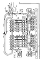
- FIGURE 1 there is shown the layout of a palletizing plant or workcell 10 in which the invention is advantageously embodied.
- the manufacturing process involves receiving spools 14 of yarn from a rail conveyor 11 and moving and sorting the spools 14 for placement on pallets 21 that are delivered on a pallet conveyor 12.
- the palletizing plant 10 includes a receiving robot 13 and its controller 13C for transferring the yarn spools 14 to a main roller conveyor 15 where spool sorting occurs. Sorting is achieved through the use of a plurality of queueing conveyors 16-1 through 16-10 and a manual queueing conveyor 16-11 that intersect with the main conveyor 15 at respective queueing stations. Diverters A through K push each spool 14 from the main conveyor 15 to the queueing conveyor to which it is assigned.
- a yarn spool 14 If a yarn spool 14 is not diverted to a queueing conveyor for some reason, it is returned to main branch 15-1 of the conveyor 15 over return conveyor branch 15-2.
- An automatically controlled escapement device 18 holds spools 14 on the main conveyor 15 during the time period when a spool 14 is reentering the main conveyor branch 15-1 from the return conveyor branch 15-2.
- a robot 19 is supported on rails 20 and operates to transfer yarn spools 14 from the queueing conveyors 16-1 through 16-5 to pallets 21 on respective indexing conveyors 22-1 through 22-5 corresponding to the queueing conveyors 16-1 through 16-5.
- Another rail supported robot 23 transfers spools 14 from the queueing conveyors 16-6 through 16-10 to indexing conveyors 22-6 through 22-10.
- Respective robot controllers 19C and 23C are provided for the robots 19 and 23.
- the spools 14 generally have a conical shape with a hollow cylindrical core 14H.
- a bar code 14B is secured to the inner core surface of each spool 14 to provide identity data including the product category.
- a molded tray 14T (FIGURE 8) is used as a carrier for each spool 14 on the main conveyor 15.
- the tray I4T includes a centrally located bump 24 for indexed positioning of the spool 14 on the tray 14T.
- the spools 14 are delivered to the workcell 10 on a package carrier shown schematically in FIGURE 9.
- the carrier 25 is suspended from the rail conveyor 11 and has a total of four spindles 26 on each of two sides 27 and 28 thereby providing a capacity for carrying eight of the spools 14.
- a positioning and rotating device (not specifically shown in FIGURE 1) holds the carrier 25 in position and rotates the carrier 25 to enable the robot 13 to unload the spools 14 from both sides of the carrier 25.
- the robot 13 takes a spool from the carrier 29 and places it on the empty tray 14T.
- the newly loaded tray 14T is then released to be roll driven along the main conveyor 15 toward the escapement 18.
- a bar code reader 30 reads the bar code on each spool 14 to identify its queueing station for palletizing. When each spool 14 reaches its identified queueing station, it is diverted onto its queueing conveyor 16 as previously described. If the bar code cannot be read or if it is in error for any particular spool, the manual queueing station 17-11 is assigned to that spool for special processing.
- Each queueing conveyor includes a holding escapement device which queues the spools 14 for entry by threes to a loading area for which there is provided another escapement device 32.
- the device 32 is operated to release the empty trays for return over a return conveyor branch 33 to the start of the process.
- the robot 19 or 23 moves along the rails 20 to the queueing line that is ready for unloading.
- the robot removes the spools 14 frim the trays 14T and places them on a pallet 21 until a layer of spools 14 is completed on the pallet.
- the robot then obtains a separator sheet from a dispenser 34A or 34B and places it on the spool layer so that a second layer of spools can then be placed on the same pallet.
- Each pallet is usually loaded with three or four layers of yarn spools.
- Various electrical input devices I1 through I54 are employed in the workcell 10 to provide status signals for logic control. Further, various electrical control devices 01 through 054 are operated by controller outputs to run the workcell in the manner described.
- smart input/output modules 75 are spaced around the work area and linked to the robot controllers.
- three input/output modules are associated with the robot 13 and only one module is assigned to each of the robots 19 or 23.
- a workcell control system 70 (FIGURE 2) includes the robot controllers 13C, 19C, and 23C to operate the robotic plant or workcell 10 in accordance with the invention.
- the electronic robot controller 13C operates the robot 13 in accordance with a user's program loaded into the controller 13C, for example through a floppy disk 72 under operator control from a programmer's console 71.
- the floppy disk 72 is also used advantageously to download programs to the input/output modules 75 as subsequently more fully described herein.
- a like operating scheme (not shown) is provided for each robot controller 19C or 23C.
- the workcell control system 70 further includes a plurality of the input/output modules 75, with the number thereof depending on the input/output needs and the layout of the particular workcell being operated. As proviously indicated, a total of 5 input/output modules 75-1 through 75-5 are employed in this case to provide a distributed intelligence interface with the input/output devices included in the workcell 10. Since the robot 13 is the onlyu one having a plurality of input/output modules 75 in this application, only the robot controller 13C will be described to illustrate the invention.
- a serial local area network bus 73 provides data communications among and between the input/output modules 75-1 through 75-3 and the robot controller 13C. Accordingly, bus connections are employed for signalling across a large area of the plant 10 and only short wire runs are needed for individual input/output device connections. Substantial reduction in wiring is thus realized while freeing up control capacity and retaining centralized control in the robotic controller 13C.
- one or more additional input/output modules 75-6 can be included in the syustem for connection to one or more respective conventional programmable logic controllers (PLCs) 76. In that event, other workcell input/output devices are wired to the PLC in the conventional manner.
- PLCs programmable logic controllers
- FIGURE 3 there is shown a generalized control loop configuration 118 preferably employed to operate each of the robots 13, 19 and 23. It is preferably implemented as a completely digital control.
- the trajectory cycle can be characterized with a cycle time in the range of 32 to 8 milliseconds depending on the employed modular configuration.
- position and velocity control loops 120 and 122 are parallel fed to the input of a torque control loop 124.
- Velocity commands are generated by block 126 from position commands received by block 128.
- feedforward acceleration commands are generated by block 130 from the velocity commands.
- Computed inertia (load and arm) 132 is multiplied against the acceleration command as indicated by reference character 134 in the feedforward acceleration control loop 136.
- the velocity command is generated in this case once every 8 to 32 milliseconds depending on the modular configuration of the robot control.
- the basic robot control described in the referenced applications has a trajectory cycle time of 32 milliseconds while the enhanced control has a trajectory cycle time of 8 milliseconds.
- a velocity command generator 138 interpolates velocity commands at the rate of 1 each millisecond which corresponds with the velocity feedback sampling rate in velocity feedback path 140.
- velocity feedback may be produced by tachometer signals which are converted from analog to digital by converter 142.
- a scaler 144 and a filter 146 round out the velocity feedback circuitry.
- an interpolator 148 generates position commands every millisecond in correspondence with the position feedback sampling rate in feedback path 150.
- position feedback is absolute and the velocity and position feedback paths 140 and 150 operate as just described (with switch 151 as shown).
- tachometers are not available and velocity feedback is computed from incremental position feedback as indicated by block 152 (with the switch 151 swinging to its other position).
- Velocity error is generated by summer 154 with gain applied by loop 156.
- position error is generated by summer 1598 with gain applied by box 160.
- Velocity and position errors and a feedforward acceleration command are summed in summer 162.
- Gain is applied to box 166 to generate a torque command which is applied to the input of torque control loop 164 every millisecond.
- Torque error is generated in summer 168 by summing the torque command (motor current command) with current feedback from feedback path 170.
- Box 172 applies a torque loop gain to the torque error and output commands (motor voltage commands) are applied to a power amplifier 174 which supplies the motor drive current for robot joint operation.
- control looping for the robot controller 72 is achieved by the use of digital control circuitry disposed on a plurality of electronic boards.
- the organization of the circuitry on the boards and the partitioning of programming among various microprocessors enables advanced robot control performance to be achieved as described in the referenced patent applications.
- control board configuration or network includes an arm interface board 800 which preferably houses all circuitry dependent on the type of robot arm being controlled.
- position feedback circuitry will differ according to whether absolute or incremental position feedback is used by the robot arm to be controlled. Any particular robot arm would require use of the arm interface board which is structured to work with that robot arm.
- the arm interface (AIF) 800 board also houses generic circuitry such as VME bus control circuitry which is generally related to two or more boards and not to any one board in particular.
- Control signals are generated from the AIF board 800 to control power block 150 which supply motor current to the respective robot joint motors.
- the AIF board 800 also includes a data bus to operate as a program and operation data channel for external coupling of the robot controller 72 to other robot controllers, if included in a work cell, as indicated by the reference character 152, and to the smart input/output modules 75, over the local area network 73.
- the VME bus couples the AIF board to an SCM board 400 for I/O operational and supervisory control, among other purposes.
- a torque processor (TP) board 600 and the servo control board (SCM) 400 are generic circuit boards used with the AIF board 800 and power amplifier blocks 150 in all robot control systems for all robot types.
- the three circuit boards 400, 600 and 800 provide complete 6-axis control for a robot arm and thus form a basic control configuration for the UNIVAL family of robot controls.
- the torque processor board 600 provides motor torque control in response to commands from the servo control board 400.
- the SCM board 400 provides arm solutions and position and velocity control in accordance with a robot control program.
- the SCM board 400 also provides for interfacing the programmer's console 71 with the input/output modules 75 and for downloading programs thereto.
- Extended control capability and/or system functioning is achieved by interconnecting additional electronic boards or devices to the basic control 400, 600, 800.
- the control can operate the robot with significantly faster control action, i.e., with a trajectory cycle shortened from thirty-two microseconds to eight microseconds.
- Interboard data communications for control and other purposes occur over multiple signal paths in a VME bus 155. Additionally, a VMX bus 156 is provided for connection between the torque processor board 600 and the AIF board 800.
- Multiple pin interconnectors (not shown in FIGURE 4) are provided on the AIF, TP and SCM boards and any other connectable units to facilitate VME and VMX interboard bus connections modular and board assembly for the robot control 30.
- Other connectors are provided on the AIF board 800 for external input/output connections.
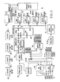
- the preferred electronic board circuitry for the smart input/output module 75 is represented by the block diagram shown in FIGURE 4.
- Local intelligence is provided for the module 75 by a microcontroller 78 (such as an 8044 device) and a coprocessing binary accelerator 81.
- the binary accelerator 81 provides solutions at hardware speed for logic equations assigned to it and thereby significantly speeds up the overall operation of the module 75.
- the microcontroller 75 has 1) an EPROM memory 79 for storage of a downloaded module operation program and 2) a RAM memory 80 for storage of user programs related to sequence logic and other control of the input/output devices associated with the module.
- the module operation program is downloaded from the robot controller 13 as previously indicated, and it executes its assigned level of control over data communications to and from the module 75 through the local area network 73 and further controls the execution of the user's programming which processes device inputs, under control of a multiplexer 94, and generates device outputs that enable the particular module 75 to provide its assigned process control.
- Box 73A identifies the station address of the module 75 for the network 73.
- a line driver 82 and a line receiver 83 and a station address detector 84 operate as part of the data communication system.
- An oscillator 84 and a counter 85 provide a timer which in this case provides four different delay times that can be used to control output pulse length.
- Device inputs are channeled from input terminal block 86-1 and 86-2 through buffers 87-1 and 87-2. Similarly, device outputs are applied to latch blocks 88-1 and 88-2 for output through terminal blocks 89-1 and 89-2.
- An address decoder 90 provides device selection for input/output operation.
- Power is supplied to the board by blocks 91, 92 and 93.
- the program stored in the EPROM memory 79 is downloaded from the floppy disk through the robot controller 13 and specifically through its AIF board 800 and through the line receiver 83 on the input/output module board 75.
- User programs that basically define the operation of the manufacturing process under control are similarly downloaded to the RAM memory 80.
- workcell operation is significantly facilitated especially since robot programming and input/output programming for process control can both be done with use of the same programming language and usually from the same work station.
- an initialization routine 250 is executed after power-up.
- Blocks 251, 252 and 253 respectively operate the microcontroller or microprocessor 78 to set up the input/output board memory structure, the timer 85 and the communicaion port through the driver/receiver circuitry 82 and 83.
- block 254 places the microcontroller 78 in its interrupt mode, i.e. idling subject to interrupt control.
- the microcontroller 78 is triggered into programmed operation by either of two basic interrupts.
- the first is a cyclic 4 millisecond interrupt from the timer 85 for status updating of the process inputs and outputs to and from the input/output module board.
- the second is a cyclic 32 millisecond interrupt from the serial communications line 73.
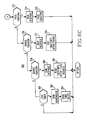
- FIGURES 6B and 6C Programmable execution of board communications is illustrated by a flow chart 260 shown in FIGURES 6B and 6C. After an interrupt 261, blocks 262 and 263 receive the transmitted control byte and identify the destination buffer number.
- block 264 indicates the command is an I/O status request, an acknowledgement is sent by block 265 and buffer and enable data are swapped by block 266. Forced data in the current buffer is then sent to the output port by block 267 and the program returns to the interrupt idle mode.
- FIGURE 6C Other possible communicated commands are shown in FIGURE 6C.
- block 274 sends an acknowledgement and block 275 executes equation packing and is followed by a return.
- block 276 detects an enable equation command
- block 278 enables or activates the identified and previously stored equation after block 277 sends an acknowledgement.
- block 279 detects a disable equation command
- block 281 resets the active flag for the identified and previously stored equation thereby disabling it.
- block 183 When a timer load command is detected by block 282, block 183 sends an acknowledgement and the new timer values are stored by block 284 for implementation in the input/output board operation.
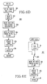
- the process I/O status updating interrupt operation is represented by a flow chart 290 shown in FIGURE 6D and a functional block diagram 297 shown in FIGURE 6E.
- block 291 When a 4 millisecond timer interrupt occurs, block 291 first sets the timer for the next cycle and block 292 then reads the process input data. Block 293 then calls for the binary accelerator 81 to solve the active equation(s). The results are masked byu block 294 with any forced output data that has been received as a higher level control command.
- FIGURE 6E shows how binary accelerator equations are either applied or not applied to process input data.
- an enable/disable switch 298 controls the application of binary accelerator logic 81 to input data according to the operation of program blocks 278 and 281. Blocks 294, 295 and 296 then operate as previously described.
- FIGURE 7 there is shown a chart illustrating the comparative value of the invention relative the prior art use of programmed logic controllers for the processing of process inputs and outputs.
- the complexity of control is plotted against cost for the prior art programmed logic controller (PLC) approach and for the distributed intelligence approach characteristic to the present invention.
- PLC programmed logic controller
- the cost of applying the present invention is better than that of the PLC approach.
- the PLC approach is comparatively better from a cost standpoint.
Landscapes
- Engineering & Computer Science (AREA)
- General Engineering & Computer Science (AREA)
- Manufacturing & Machinery (AREA)
- Quality & Reliability (AREA)
- Physics & Mathematics (AREA)
- General Physics & Mathematics (AREA)
- Automation & Control Theory (AREA)
- Manipulator (AREA)
- Numerical Control (AREA)
Applications Claiming Priority (2)
| Application Number | Priority Date | Filing Date | Title |
|---|---|---|---|
| US07/304,972 US4896087A (en) | 1989-01-31 | 1989-01-31 | Robotic workcell control system having improved input/output interfacing for better workcell operation |
| US304972 | 1999-05-04 |
Publications (2)
| Publication Number | Publication Date |
|---|---|
| EP0381599A2 true EP0381599A2 (de) | 1990-08-08 |
| EP0381599A3 EP0381599A3 (de) | 1992-01-08 |
Family
ID=23178750
Family Applications (1)
| Application Number | Title | Priority Date | Filing Date |
|---|---|---|---|
| EP19900420045 Withdrawn EP0381599A3 (de) | 1989-01-31 | 1990-01-30 | Steuerungssystem für Roboter-Fertigungszellen mit verbessertem Ein/Ausgangsinterface für bessere Fertigungszellenfunktion |
Country Status (2)
| Country | Link |
|---|---|
| US (1) | US4896087A (de) |
| EP (1) | EP0381599A3 (de) |
Cited By (2)
| Publication number | Priority date | Publication date | Assignee | Title |
|---|---|---|---|---|
| EP3657277A1 (de) * | 2018-11-23 | 2020-05-27 | Siemens Aktiengesellschaft | Erweiterungsvorrichtung für eine automatisierungsvorrichtung |
| RU2779903C1 (ru) * | 2018-11-23 | 2022-09-15 | Сименс Акциенгезелльшафт | Устройство расширения для автоматизированного устройства |
Families Citing this family (22)
| Publication number | Priority date | Publication date | Assignee | Title |
|---|---|---|---|---|
| US5204942A (en) * | 1989-01-10 | 1993-04-20 | Kabushiki Kaisha Kobe Seiko Sho | Robot control system for controlling a set of industrial robots for cooperative operation |
| US5179329A (en) * | 1989-04-25 | 1993-01-12 | Shinko Electric Co., Ltd. | Travel control method, travel control device, and mobile robot for mobile robot systems |
| JPH0310780A (ja) * | 1989-06-05 | 1991-01-18 | Mitsubishi Electric Corp | 産業用ロボツト装置 |
| US5345540A (en) * | 1991-07-12 | 1994-09-06 | Hewlett-Packard Company | Methods for automatically programming spatial information in robotic systems |
| US5268837A (en) * | 1992-04-23 | 1993-12-07 | Digital Equipment Corporation | Robotics workstation |
| US5914880A (en) * | 1992-05-16 | 1999-06-22 | Nippei Toyama Corporation | Method and apparatus for controlling a transfer machine |
| US5513096A (en) * | 1992-07-10 | 1996-04-30 | Connecticut Innovations, Inc. | Multi-axis motion controller and lid dispenser |
| JPH06309011A (ja) * | 1993-04-08 | 1994-11-04 | Internatl Business Mach Corp <Ibm> | Faシステムの生産セル制御装置 |
| AU5555196A (en) * | 1995-04-19 | 1996-11-07 | Dct, Inc. | Industrial workcell system and method |
| US6359249B1 (en) | 1995-04-19 | 2002-03-19 | Dct, Inc. | No wat welding system |
| US5742022A (en) * | 1995-04-19 | 1998-04-21 | Dct Avanced Engineering, Inc. | Industrial workcell system and method |
| US5909674A (en) * | 1996-12-23 | 1999-06-01 | Philips Electronics North America Corp. | Method for optimizing the layout and charge maps of a flowline of pick and place machines |
| US5864833A (en) * | 1996-12-23 | 1999-01-26 | Philips Electronics North American Corp. | Apparatus for optimizing the layout and charge maps of a flowline of pick and place machines |
| JP3236563B2 (ja) * | 1998-06-19 | 2001-12-10 | ファナック株式会社 | 制御装置 |
| US6573470B1 (en) | 1998-08-05 | 2003-06-03 | Dct, Inc. | Weld gun heat removal |
| US6512194B1 (en) | 1999-11-19 | 2003-01-28 | Dct, Inc. | Multi-arm weld gun |
| JP2003308221A (ja) * | 2002-04-12 | 2003-10-31 | Nec Corp | ロボット制御システムと方法並びにプログラム |
| US8315736B2 (en) * | 2008-04-25 | 2012-11-20 | Fanuc Robotics America, Inc. | Method and apparatus for picking/packing applications |
| DE102008046325A1 (de) * | 2008-08-29 | 2010-03-11 | SSI Schäfer PEEM GmbH | Verfahren und Vorrichtung zum mannlosen, vollautomatisierten Kommissionieren von Artikeln in Auftragsladehilfsmittel |
| GB2501676A (en) | 2012-03-30 | 2013-11-06 | Torquing Technology Ltd | Autonomous cell control system |
| EP2865621B1 (de) * | 2013-10-28 | 2015-09-23 | Intrion Nv | Verfahren und Anordnung für automatische Schichtaufnahme |
| US11590659B2 (en) | 2019-07-02 | 2023-02-28 | Intelligrated Headquarters, Llc | Robotic sortation system |
Family Cites Families (6)
| Publication number | Priority date | Publication date | Assignee | Title |
|---|---|---|---|---|
| US4661680A (en) * | 1985-06-28 | 1987-04-28 | Westinghouse Electric Corp. | End-of-arm tooling carousel apparatus for use with a robot |
| US4760521A (en) * | 1985-11-18 | 1988-07-26 | White Consolidated Industries, Inc. | Arbitration system using centralized and decentralized arbitrators to access local memories in a multi-processor controlled machine tool |
| EP0269374A3 (de) * | 1986-11-20 | 1988-08-24 | Unimation Inc. | Modules Kontrollsystem für einen Roboter |
| US4835730A (en) * | 1987-02-27 | 1989-05-30 | Adept Technology, Inc. | Database driven robot programming system and method |
| JP2834122B2 (ja) * | 1987-07-08 | 1998-12-09 | 株式会社日立製作所 | 制御装置 |
| US4787297A (en) * | 1987-08-27 | 1988-11-29 | Texas Instruments Incorporated | Stacked robotic work cell process station |
-
1989
- 1989-01-31 US US07/304,972 patent/US4896087A/en not_active Expired - Lifetime
-
1990
- 1990-01-30 EP EP19900420045 patent/EP0381599A3/de not_active Withdrawn
Cited By (4)
| Publication number | Priority date | Publication date | Assignee | Title |
|---|---|---|---|---|
| EP3657277A1 (de) * | 2018-11-23 | 2020-05-27 | Siemens Aktiengesellschaft | Erweiterungsvorrichtung für eine automatisierungsvorrichtung |
| WO2020104141A1 (en) * | 2018-11-23 | 2020-05-28 | Siemens Aktiengesellschaft | Extension device for an automation device |
| RU2779903C1 (ru) * | 2018-11-23 | 2022-09-15 | Сименс Акциенгезелльшафт | Устройство расширения для автоматизированного устройства |
| US12216454B2 (en) | 2018-11-23 | 2025-02-04 | Siemens Aktiengesellschaft | Extension device for an automation device |
Also Published As
| Publication number | Publication date |
|---|---|
| EP0381599A3 (de) | 1992-01-08 |
| US4896087A (en) | 1990-01-23 |
Similar Documents
| Publication | Publication Date | Title |
|---|---|---|
| US4896087A (en) | Robotic workcell control system having improved input/output interfacing for better workcell operation | |
| US6718229B1 (en) | Linear actuator palletizing system and method | |
| US4962338A (en) | Universal robot control board configuration | |
| US4763055A (en) | Digital robot control having high performance servo control system | |
| EP0268495A2 (de) | Modules Kontrollsystem für einen Roboter | |
| US20100030375A1 (en) | Control method for a complex consisting of a plurality of multiaxial handling devices arranged in succession and/or side by side, and also data storage medium, control system and complex | |
| US12172320B2 (en) | System, method and storage medium for production system automatic control | |
| EP0269374A2 (de) | Modules Kontrollsystem für einen Roboter | |
| US5838572A (en) | Real-time interrupt driven PC control system for a storage and retrieval machine | |
| EP3933520B1 (de) | Industrielles steuerungssystem mit einer mehrschichtigen steuerlogikausführung | |
| US5025390A (en) | Robotic workcell control system with a binary accelerator providing enhanced binary calculations | |
| US4845627A (en) | Remote programmable controller | |
| SE512647C2 (sv) | Förfarande och styrsystem för att styra ett transportörsystem samt en anläggning för balning av pappersmassa | |
| EP0407612B1 (de) | Extern erweiterbare speicherprogrammierbare steuerung | |
| Almeida et al. | Automatic logic generation for reconfigurable cell-based manufacturing systems | |
| CN119637544B (zh) | 码垛装置的控制方法、装置、存储介质和电子设备 | |
| Hussaini et al. | Multiple manipulators and robotic workcell coordination | |
| JPH0619660B2 (ja) | 分散形数値制御装置 | |
| Weston et al. | Intelligent interfaces for robots | |
| Hace et al. | The open CNC controller for a cutting machine | |
| Sekerinski | Production cell | |
| JPH0756623A (ja) | セルコントローラ | |
| EP0479849B1 (de) | Materialverarbeitungsverfahren | |
| CN108382666A (zh) | 包膜系统及包膜方法 | |
| Faucett et al. | A highly flexible automated odd-form component assembly cell |
Legal Events
| Date | Code | Title | Description |
|---|---|---|---|
| PUAI | Public reference made under article 153(3) epc to a published international application that has entered the european phase |
Free format text: ORIGINAL CODE: 0009012 |
|
| AK | Designated contracting states |
Kind code of ref document: A2 Designated state(s): CH DE DK ES FR GB IT LI SE |
|
| PUAL | Search report despatched |
Free format text: ORIGINAL CODE: 0009013 |
|
| AK | Designated contracting states |
Kind code of ref document: A3 Designated state(s): CH DE DK ES FR GB IT LI SE |
|
| STAA | Information on the status of an ep patent application or granted ep patent |
Free format text: STATUS: THE APPLICATION IS DEEMED TO BE WITHDRAWN |
|
| 18D | Application deemed to be withdrawn |
Effective date: 19920609 |