EP0381629B1 - Assemblage de pont extensible et mobile pour construire des tunnels - Google Patents
Assemblage de pont extensible et mobile pour construire des tunnels Download PDFInfo
- Publication number
- EP0381629B1 EP0381629B1 EP90830001A EP90830001A EP0381629B1 EP 0381629 B1 EP0381629 B1 EP 0381629B1 EP 90830001 A EP90830001 A EP 90830001A EP 90830001 A EP90830001 A EP 90830001A EP 0381629 B1 EP0381629 B1 EP 0381629B1
- Authority
- EP
- European Patent Office
- Prior art keywords
- platform
- counter
- bridge assembly
- central body
- welded
- Prior art date
- Legal status (The legal status is an assumption and is not a legal conclusion. Google has not performed a legal analysis and makes no representation as to the accuracy of the status listed.)
- Expired - Lifetime
Links
- 230000000087 stabilizing effect Effects 0.000 claims abstract description 5
- 239000002184 metal Substances 0.000 claims description 8
- 230000008878 coupling Effects 0.000 claims description 7
- 238000010168 coupling process Methods 0.000 claims description 7
- 238000005859 coupling reaction Methods 0.000 claims description 7
- 238000010276 construction Methods 0.000 claims description 5
- 230000000452 restraining effect Effects 0.000 claims description 3
- 230000003014 reinforcing effect Effects 0.000 abstract description 2
- 239000003381 stabilizer Substances 0.000 abstract 1
- 230000004048 modification Effects 0.000 description 1
- 238000012986 modification Methods 0.000 description 1
Images

Classifications
-
- B—PERFORMING OPERATIONS; TRANSPORTING
- B66—HOISTING; LIFTING; HAULING
- B66F—HOISTING, LIFTING, HAULING OR PUSHING, NOT OTHERWISE PROVIDED FOR, e.g. DEVICES WHICH APPLY A LIFTING OR PUSHING FORCE DIRECTLY TO THE SURFACE OF A LOAD
- B66F11/00—Lifting devices specially adapted for particular uses not otherwise provided for
- B66F11/04—Lifting devices specially adapted for particular uses not otherwise provided for for movable platforms or cabins, e.g. on vehicles, permitting workmen to place themselves in any desired position for carrying out required operations
- B66F11/044—Working platforms suspended from booms
Definitions
- the present invention relates to an extensible movable bridge assembly, comprising several cooperating parts for performing, in a tunnel being built, operations such as the loading of mines, laying of reinforcing ribs and nets and the like.
- the document FR-A-2 266 656 discloses an extensible movable bridge assembly having substantially the features of the pre-characterizing part of the main claim.
- the aim of the present invention is to provide such an extensible movable bridge assembly which can be quickly and easily moved and installed.
- a main object of the invention is to provide such an extensible movable bridge assembly which is very simple construction wise and very reliable in operation.
- an extensible movable bridge assembly for use in building tunnels, having the features of the characterizing part of the main claim.
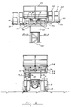
- the extensible movable bridge assembly for making tunnels comprises a bridge frame, overally indicated at the reference number 1, which is affixed, by four brackets 2, to the chassis of a truck 3.
- the bridge frame essentially comprises four section members HE, (4), extending horizontally and welded, at respective end portions thereof, to two section members "HE", of like cross-section, so as to define a rectangular construction.
- stabilizing pistons 5 which are bolted to welded metal sheet box-like bodies 6.
- a central body 7 made of welded sheet metal and which is arranged at the cabin of the truck.
- This central body comprises four hinges for pivotably coupling raising arm members for raising a counter-platform which will be disclosed in a more detailed way hereinafter.
- first access ladder 8 There are moreover provided a first access ladder 8, two guard walls 9 and 10 and a second ladder 11 for accessing the platform.
- the top raising arm comprises four C-shape section members welded in pairs and mutually spaced by a L-shape section member lattice 13.
- This top raising arm bears a hinge coupling portion for pivotably coupling the head portion of a raising piston 14 which is also articulated to the beams 4 of the frame.
- the top arm is articulated, at one end thereof, to the central body and, at the other end thereof, to a central body 15 for supporting the above mentioned counter-platform.
- the arm 12 As the arm 12 is arranged at a lowered position, it will rest, through the legs 16, on the frame 1.
- a second raising arm 17 also made of four C-shape section members, welded in pairs and mutually spaced by a L-shape section member lattice 13'.
- This second raising arm is pivoted, at one end thereof, to said central body 7 and, at the other end thereof, to the central body 15 of the counter-platform 18.
- the above mentioned central body 15 is made of a welded and suitably ribbed metal sheet, and bears the pivot hinges for the raising arms 12 and 17.
- the counter-platform in turn, comprises beams HE, (19), welded to the central body 15 and bearing horizontal rollers 20 on which a platform, overally indicated at 21, can slide.
- the above platform in particular, is driven by a cylinder 23 which is respectively pivoted to said platform and counter-platform 18.
- the platform 21 comprises moreover guard walls 24, a floor 25, made of HE and IPE beams, a sheet metal covering, as well as abutment rollers 26 for said beams 19, which rollers are provided for sliding said platform along said counter-platform 18.
- a leg bearing frame 27 is moreover provided, made of square-cross-section tubular elements, in the inside of said frame 27 there being provided tracks 28, made of C-shape section members, and bearing a panel on which slide the wheels 29 of leg or wing members 30.
- These legs are arranged under the mentioned floor 25 and are included in said frame 27 which, on vertical sides thereof, supports roller pairs 31 for restraining said legs.
- Said legs in particular are provided with removable galleries 32 and comprise a respective piston 33 for driving said legs to perform extension and withdrawing movements.
- a main feature of the invention is that in the subject extensible movable bridge assembly, the stabilizing elements, raising arms, platform and legs are driven by means of independent drives.
Landscapes
- Engineering & Computer Science (AREA)
- Structural Engineering (AREA)
- Life Sciences & Earth Sciences (AREA)
- Geology (AREA)
- Mechanical Engineering (AREA)
- Bridges Or Land Bridges (AREA)
- Conveying And Assembling Of Building Elements In Situ (AREA)
- Tents Or Canopies (AREA)
Claims (8)
- Un assemblage extensible de pont mobile, pour l'utilisation dans la construction de tunnels, comprenant un cadre (1) fixé à un camion (3) sur le châssis duquel deux bras élévateurs (12) sont pivotés qui portent une plateforme contre-boutante (18), ladite plateforme contre-boutante (18) supportant une plateforme (21) pourvue de pieds (30), un dispositif oléodinamique à piston étant en plus prévu pour commander les éléments (12, 18, 21, 30) mentionnés indépendamment les uns des autres, caractérisé en ce qu'avec ladite plateforme (21) un cadre (27) avec un pied est rigidement accouplé, qui est fait en éléments tubulaires avec une coupe transversale carrée à l'intérieur desquels des glissières de guidage (28) en éléments profilés en forme de C sont prévues, qui portent un panneau sur lequel les roues (29) desdits pieds (30) glissent, lesdits pieds (30) étant arrangés au-dessus d'une passerelle (25) de ladite plateforme (21) et étant tenus dans le cadre (27) portant ledits pieds qui porte aussi des paires de rouleaus (31) à axe vertical pour retenir lesdits pieds (30).
- Un assemblage de pont selon la Revendication 1 caractérisé en ce que ledit cadre (1) est fixé audit châssis de camion (3) avec quatre agrafes (2), ledit cadre comprenant quatre éléments profilés (HE) s'étendants horizontalement et soudés, près des leurs extrémités, à deux éléments profilés (HE) avec une coupe transversale similaire ainsi définant une construction rectangulaire, des pistons stabilisateurs (5) étant fixés aux angles de ladite construction et boulonnés à des corps en forme de boîte (6) en feuille métallique soudée.
- Un assemblage extensible de pont mobile selon les Revendications 1 et 2 caractérisé en ce que ledit assemblage en plus comprend un corps central (7) soudé auxdits éléments profilés (HE), ledit corps central (7) étant fait en feuille métallique crénelée soudée et arrangé près de la cabine dudit camion (3), ledit corps central (7) comprenant quatre articulations pour accoupler pivotablement les bras pour éléver ladite plateforme contre-boutante (18), ledit pont en plus comprenant une première échelle (8), deux parois de protection (9, 10), une seconde échelle (11) pour acceder à ladite plateforme (21) et le siège de l'accouplement articulé de la base du piston élévateur (14).
- Un assemblage extensible de pont mobile selon l'une ou plusieures des Revendications précédentes caractérisé en ce que le bras élévateur supérieur (12) comprend quatre éléments profilés en forme de C soudés en paires et écartés entre eux par un treillis (13) d'éléments profilés en forme de L, ledit bras élévateur supérieur (12) porte une articulation à charnière pour la tête dudit piston élévateur (14) qui est aussi pivoté autour des poutrelles (4) dudit cadre, ledit bras supérieur (12) étant articulé, en proximité d'une de ses extrémités, au corps central (7) dudit cadre (1) et à son autre extrémité à un corps central (15) supportant ladite plateforme contre-boutante (18).
- Un assemblage extensible de pont mobile selon l'une ou plusieures des Revendications précédentes caractérisé en ce que le bras élévateur inférieur (17) comprend quatre éléments profilés en forme de C soudés en paires et écartés entre eux par un treillis (13') d'éléments profilés en forme de L, ledit bras inférieur (17) étant pivoté, en proximité d'une de ses extrémités, autour dudit corps central (7) et à l'extrémité opposée autour du corps central (15) de ladite plateforme contre-boutante (18).
- Un assemblage extensible de pont mobile selon l'une ou plusieures des Revendications précédentes caractérisé en ce que ledit corps central (15) de ladite plateforme contre-boutante (18) est fait en feuille métallique soudée et crénelée et porte les charnières pour accoupler à pivotement lesdits bras élévateurs, ladite plateforme contre-boutante (18) comprenant des poutrelles HE (19) soudées audit corps central (15) et portantes des rouleaus horizontaux (20) sur lesquels une plateforme peut glisser, des rouleaus à axe vertical (22) étant en plus prévus pour déplacer à glissement ladite plateforme (21) sur ladite plateforme contre-boutante (18).
- Un assemblage extensible de pont mobile selon l'une ou plusieures des Revendications précédentes caractérisé en ce que ladite plateforme (21) comprend des parois de protection (24), une passerelle (25) faite en poutrelles HE et IPE avec un recouvrement en feuille métallique, et des rouleaus d'aboutissement (26) pour les poutrelles (19) de ladite plateforme contre-boutante (18), lesdits rouleaus d'aboutissement (26) étant adaptés à permettre à ladite plateforme (21) à glisser le long de ladite plateforme contre-boutante (18).
- Un assemblage extensible de pont mobile selon l'une ou plusieures des Revendications précédentes caractérisé en ce que lesdits pieds (30) sont pourvus de galleries amovibles (32) et comprennent tous un respectif piston (33) qui commande ledit pied (30) pour des mouvements d'extension et de retraite, ledit piston (33) étant pivoté autour du pied respectif et du cadre portant le pied.
Priority Applications (1)
| Application Number | Priority Date | Filing Date | Title |
|---|---|---|---|
| AT90830001T ATE99642T1 (de) | 1989-01-31 | 1990-01-02 | Ausfahrbarer und beweglicher brueckenzusammenbau zum bauen von tunneln. |
Applications Claiming Priority (2)
| Application Number | Priority Date | Filing Date | Title |
|---|---|---|---|
| IT1926989 | 1989-01-31 | ||
| IT8919269A IT1228084B (it) | 1989-01-31 | 1989-01-31 | Ponte mobile sviluppabile, comprendente piu' parti cooperanti, atto ad effettuare, in una galleria in costruzione, il caricamento delle mine, il fissaggio delle centine, la posa delle reti e qualsiasi altro intervento manuale, che debba essere necessariamente effettuato in quota. |
Publications (2)
| Publication Number | Publication Date |
|---|---|
| EP0381629A1 EP0381629A1 (fr) | 1990-08-08 |
| EP0381629B1 true EP0381629B1 (fr) | 1994-01-05 |
Family
ID=11156276
Family Applications (1)
| Application Number | Title | Priority Date | Filing Date |
|---|---|---|---|
| EP90830001A Expired - Lifetime EP0381629B1 (fr) | 1989-01-31 | 1990-01-02 | Assemblage de pont extensible et mobile pour construire des tunnels |
Country Status (4)
| Country | Link |
|---|---|
| EP (1) | EP0381629B1 (fr) |
| AT (1) | ATE99642T1 (fr) |
| DE (1) | DE69005657T2 (fr) |
| IT (1) | IT1228084B (fr) |
Families Citing this family (8)
| Publication number | Priority date | Publication date | Assignee | Title |
|---|---|---|---|---|
| DE4141812A1 (de) * | 1991-12-18 | 1993-06-24 | Spezialfahrzeugaufbau Und Kabe | Teleskopierbare turmwagenarbeitsbuehne |
| ITMO20110129A1 (it) * | 2011-05-24 | 2012-11-25 | Paolo Balugani | Piattaforma di lavoro aerea, particolarmente per interventi su superfici inclinate o curve. |
| PL409531A1 (pl) * | 2014-09-17 | 2016-03-29 | Wojskowy Instytut Techniki Inżynieryjnej Im. Profesora Józefa Kosackiego | Urządzenie do budowy podpór mostowych |
| CN107060844B (zh) * | 2017-06-06 | 2023-09-26 | 中铁工程装备集团隧道设备制造有限公司 | 隧道用两臂两篮钢拱架安装机及钢拱架施工方法 |
| CN109322682B (zh) * | 2018-11-22 | 2024-03-19 | 长沙科达智能装备股份有限公司 | 一种拱架台车用机械手 |
| IT201900010011A1 (it) * | 2019-06-25 | 2020-12-25 | Palazzani Ind S P A | Piattaforma di lavoro aerea con dispositivo di sollevamento del cestello |
| CN112158784B (zh) * | 2020-10-30 | 2021-11-23 | 徐州徐工随车起重机有限公司 | 一种多平台可折叠隧道养护作业装置 |
| CN115043364B (zh) * | 2022-06-07 | 2023-06-16 | 国网安徽省电力有限公司池州供电公司 | 一种基于电力系统的智能检修辅助装置 |
Family Cites Families (6)
| Publication number | Priority date | Publication date | Assignee | Title |
|---|---|---|---|---|
| GB933693A (en) * | 1960-01-20 | 1963-08-08 | Wharton Engs Elstree Ltd | Improvements relating to elevating platforms and the like particularly for workmen |
| US3253717A (en) * | 1964-04-27 | 1966-05-31 | Sterling Prec Corp | Stiff leg outrigger for fire trucks and the like |
| DE1481911A1 (de) * | 1967-03-03 | 1969-10-23 | Eisenbau Karl Ladwig | Fahrbares Hubgeruest |
| US3529694A (en) * | 1969-03-10 | 1970-09-22 | George L Atchey | Portable collapsible scaffold |
| FR2266656A1 (en) * | 1974-04-03 | 1975-10-31 | Gacquerelle Gerard | Mobile overhead working platform - has boom with parallelogram linkage supporting slewing and sliding platform |
| DE2535823A1 (de) * | 1975-08-12 | 1977-02-24 | Beukenberg Maschf | Hilfsvorrichtung fuer den einsatz in untertaegigen strecken, stollen, tunneln usw. |
-
1989
- 1989-01-31 IT IT8919269A patent/IT1228084B/it active
-
1990
- 1990-01-02 EP EP90830001A patent/EP0381629B1/fr not_active Expired - Lifetime
- 1990-01-02 AT AT90830001T patent/ATE99642T1/de not_active IP Right Cessation
- 1990-01-02 DE DE69005657T patent/DE69005657T2/de not_active Expired - Fee Related
Also Published As
| Publication number | Publication date |
|---|---|
| DE69005657D1 (de) | 1994-02-17 |
| IT1228084B (it) | 1991-05-28 |
| DE69005657T2 (de) | 1994-07-07 |
| ATE99642T1 (de) | 1994-01-15 |
| EP0381629A1 (fr) | 1990-08-08 |
| IT8919269A0 (it) | 1989-01-31 |
Similar Documents
| Publication | Publication Date | Title |
|---|---|---|
| US4627784A (en) | Loading and unloading apparatus for a vehicle | |
| US3620564A (en) | Mobile center | |
| US5299653A (en) | Work station with mobile elevatable work platform | |
| US5004188A (en) | Airbridge | |
| US4930598A (en) | Scissors lift apparatus | |
| US4456421A (en) | Lifting apparatus | |
| US4392682A (en) | Expansible and retractable vehicle body | |
| US4074790A (en) | Vehicle-borne inspection and maintenance apparatus | |
| US4530232A (en) | Frame and body repair apparatus | |
| PL127964B1 (en) | Apparatus for setting up temporary roof support in a heading | |
| US4333194A (en) | Aircraft loader with revolving cab | |
| EP0381629A1 (fr) | Assemblage de pont extensible et mobile pour construire des tunnels | |
| US4299528A (en) | Combination wheelchair lift and steps for vehicle doorways | |
| US4861094A (en) | Curtain sided trailers | |
| US5148751A (en) | Bridging mechanism for crossing railroad tracks with vertically moving pivot carriage for bridge plate | |
| ATE133461T1 (de) | Dachgaube | |
| US4946003A (en) | Mobile and aerial lift having offset boom support | |
| CA1139271A (fr) | Appareil de levage a monter sur vehicule de transport de gros elements de charpente | |
| GB2069950A (en) | Support arrangement for vehicle cranes, building machines and other apparatus. | |
| CN222989726U (zh) | 爬梯高空作业平台 | |
| EP4147914A1 (fr) | Support d'échelle | |
| JPS61162680A (ja) | 自動車用パ−キング装置 | |
| GB641407A (en) | Improvements in or relating to elevating mechanism primarily for vehicle tail boards | |
| JPH0415834Y2 (fr) | ||
| JP2733738B2 (ja) | 作業車両 |
Legal Events
| Date | Code | Title | Description |
|---|---|---|---|
| PUAI | Public reference made under article 153(3) epc to a published international application that has entered the european phase |
Free format text: ORIGINAL CODE: 0009012 |
|
| AK | Designated contracting states |
Kind code of ref document: A1 Designated state(s): AT CH DE ES FR GB GR LI SE |
|
| 17P | Request for examination filed |
Effective date: 19901204 |
|
| 17Q | First examination report despatched |
Effective date: 19920714 |
|
| GRAA | (expected) grant |
Free format text: ORIGINAL CODE: 0009210 |
|
| AK | Designated contracting states |
Kind code of ref document: B1 Designated state(s): AT CH DE ES FR GB GR LI SE |
|
| PG25 | Lapsed in a contracting state [announced via postgrant information from national office to epo] |
Ref country code: SE Effective date: 19940105 Ref country code: LI Effective date: 19940105 Ref country code: GR Free format text: LAPSE BECAUSE OF FAILURE TO SUBMIT A TRANSLATION OF THE DESCRIPTION OR TO PAY THE FEE WITHIN THE PRESCRIBED TIME-LIMIT Effective date: 19940105 Ref country code: ES Free format text: THE PATENT HAS BEEN ANNULLED BY A DECISION OF A NATIONAL AUTHORITY Effective date: 19940105 Ref country code: CH Effective date: 19940105 |
|
| REF | Corresponds to: |
Ref document number: 99642 Country of ref document: AT Date of ref document: 19940115 Kind code of ref document: T |
|
| REF | Corresponds to: |
Ref document number: 69005657 Country of ref document: DE Date of ref document: 19940217 |
|
| REG | Reference to a national code |
Ref country code: CH Ref legal event code: PL |
|
| ET | Fr: translation filed | ||
| PLBE | No opposition filed within time limit |
Free format text: ORIGINAL CODE: 0009261 |
|
| STAA | Information on the status of an ep patent application or granted ep patent |
Free format text: STATUS: NO OPPOSITION FILED WITHIN TIME LIMIT |
|
| 26N | No opposition filed | ||
| PG25 | Lapsed in a contracting state [announced via postgrant information from national office to epo] |
Ref country code: GB Effective date: 19950102 Ref country code: AT Effective date: 19950102 |
|
| GBPC | Gb: european patent ceased through non-payment of renewal fee |
Effective date: 19950102 |
|
| PG25 | Lapsed in a contracting state [announced via postgrant information from national office to epo] |
Ref country code: FR Effective date: 19950929 |
|
| PG25 | Lapsed in a contracting state [announced via postgrant information from national office to epo] |
Ref country code: DE Effective date: 19951003 |
|
| REG | Reference to a national code |
Ref country code: FR Ref legal event code: ST |